To avoid these ads, REGISTER NOW!

Lincoln compressor pump Model 9201

My64bit

Member
Joined
Dec 4, 2015
Messages
21
Ok, so I farmed some of this info from a previous post on the same compressor. All the photo's that had been posted were gone, and I think other member replies as well. I am really hopping someone can help with my issue. I will try to get pictures to post soon. There is some stuff in the way I need to move.

So the compressor I have is a Lincoln pump Model 9201. The model number on the data plate of the pump says 9201, and on the side of the pump case is has the number 5515. The serial number says 310-21, and another number below that is 369871-L. I am beginning to think that means its a 310 pump, ROC (record of change) 21. From looking at other stuff online I think this is a quincy 310 pump, is that correct? Am I correct on the model of this pump?

The tank to the compressor is stamped with a date of 1940. It's a two stage pump I believe, and it runs very quiet. I am looking for a manual or a source for parts. The valve thing at the top of the pump leaks air when the compressor is running. I believe this is a compression relief valve? It was working fine, and would let of some air when starting to run and then would stop. The air line goes down the side of the pump to a square block which has a bolt in the center with a spring behind it, behind the spring is a small steel ball about the size of a BB. I have had the unit out of the case. It has large O-ring seals around some sort of pressure valve it looks like. I am guessing this is not functioning properly? the air leaks from something that looks like a sort of valve on top of the cylinder head.

Anything anyone can tell me about getting parts in the future or at least to fix that leak would be greatly appreciated. It has been completely stripped and restored by a friend and looks beautiful, it's quiet and I love it as I can run it at night and the neighbors don't complain.
 
To avoid these ads, REGISTER NOW!

redmondjp

Well-known member
Joined
Nov 25, 2014
Messages
2,318
Location
Redmond, WA
Yes, it sounds like you have a Quincy 310 ROC 21 pump, and that you unloader is leaking (probably is a bad diaphragm). Others here can chime in but you should still be able to find parts and manuals are available from Quincy as well as other sources online.
 

MacMcMacmac

Well-known member
Joined
Oct 21, 2014
Messages
1,605
Location
canada
Are you getting any oil pressure? If not, the system is working as designed and trying to save your pump. Otherwise, you might have bad cup seals in the hydraulic unloader valve on the side of the crankcase. The unloader valve might be in upside down as well.
 
OP
M

My64bit

Member
Joined
Dec 4, 2015
Messages
21
Thank you for the input.

Mac, The pressure gauge on the engine is holding at 27 psi.
What are the "Cup Seals" and how can I tell if they are bad?
I have had what I believe you call the "Hydraulic Unloader" out and inspected it. There are small steel airlines both in & out. In the center of the block there is a bolt type plug with a spring behind it and behind the spring is a small BB sized steel ball. There are markings on the air inlet and outlet one side has a D and the other an R. I had that unit out and it is a spring loaded device with large O-ring type seals where it slides into the case. I am going to take some photo's later today. Just need to get a few things out of the way first.

Red, is the Diaphragm portion of the Uploader located in the side of the pumps crankcase, or at the top of the cylinder head?

I really need to locate a Shop Service Manual for this thing. I am going to work on locating Quincy as well.

Once again, thank you for the help.
 
Last edited:

MacMcMacmac

Well-known member
Joined
Oct 21, 2014
Messages
1,605
Location
canada
Ok, 27psi is more than enough to cause the hydraulic unloader to function unless the seals on the plunger inside have worn to the point that they no longer cause the plunger to move, the plunger is stuck, the seat the little ball rests on has perished, or the mechanical bits inside the unloader tower on the top of the head have malfunctioned. These parts can sometimes corrode into place and leave the unloader mechanism activated even when the air signal has been removed. When this happens, the air goes away, but the pins that hold the valve disc off the seat do not retract, leaving that cylinder unloaded and causing the air from that cylinder to be exhausted out of the unloader tower. Sometimes the aluminum puck under the diaphragm in the tower will seize up, or the shaft it works against will seize up, or rarely, the pins themselves seize up inside the valve body. It is very simple to test this, just take the copper line off of the top of the tower, undo the six bolts around the hexagonal cap and pull it off. Remove the diaphragm (may be dried out and cracked) and push down on the aluminum puck. It should go down with a good push and immediately retract when you let off. If that checks out, I'd unscrew the unloader tower and check to see if the oring in the big brass plunger is still good. If it has split of flattened out, it will not seal the air inside the tower when the plunger retracts. For an idea of the parts involved, see this thread on the 325 refurbish:

http://www.garagejournal.com/forum/showthread.php?t=309858&page=2
 
OP
M

My64bit

Member
Joined
Dec 4, 2015
Messages
21
Thank you Mac, that site has allot of info, and the pic's help also. It's getting late, and I am beat. I will see if I can get the one at cylinder top apart. I will take some pictures also.
 
OP
M

My64bit

Member
Joined
Dec 4, 2015
Messages
21
d2f2afe.jpg


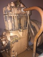
The entire compressor unit, tank & motor.
 
Last edited:
OP
M

My64bit

Member
Joined
Dec 4, 2015
Messages
21
e8a8f67.jpg


The square piece with the steel lines on the case side is what I took apart before. The O-ring seals looked good, I am not sure how to tell if it is functioning properly.
 
Last edited:
OP
M

My64bit

Member
Joined
Dec 4, 2015
Messages
21
e5c762f.jpg


The square piece with the steel lines on the case side is what I took apart before. The O-ring seals looked good, I am not sure how to tell if it is functioning properly.
 
Last edited:
OP
M

My64bit

Member
Joined
Dec 4, 2015
Messages
21
f725548.jpg


This is the valve cap from next to the unloader valve.
 
Last edited:
To avoid these ads, REGISTER NOW!
OP
M

My64bit

Member
Joined
Dec 4, 2015
Messages
21
fc7b168.jpg


I believe this is called "The Cap?" it screws onto the threaded piece still on the head with the other component still inside of it.
 
Last edited:
OP
M

My64bit

Member
Joined
Dec 4, 2015
Messages
21
fa83bac.jpg


Photo of internal spring and the valve that goes through the spring. I see no O-ring seals on this part.
 
Last edited:
OP
M

My64bit

Member
Joined
Dec 4, 2015
Messages
21
04952dd.jpg


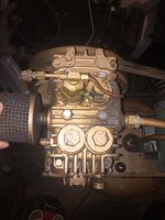
Photo of cylinder head with unloader valve removed. I do not know how to remove the rest of this unit, help would be appreciated.
 
Last edited:
OP
M

My64bit

Member
Joined
Dec 4, 2015
Messages
21
I had trouble with photo hosting from Dropbox, the images were not showing. So I reposted them all from a different service. I hope this works better, my images are huge I know.
 
OP
M

My64bit

Member
Joined
Dec 4, 2015
Messages
21
Ok, so I cleaned up all these parts and reassembled everything and it was still doing the same thing. I was starting to pull the lower section on the side apart again when i decided to pull the air lines and rotate it 180 degrees. Put things back together and whadda ya know, she's making air and running quite like a purring kitten. Shut her down, a couple seconds later she lets off a little **** of air, fire her up and she lets out another little puff or two and then quiets down to start making air. It quit working properly while I was away and my 18 y/o son was using it. I am starting to wonder if he was pulling things apart and putting them back together and got that in backwards. Anyway, it is up and running. But I still need a full manual for this compressor.
Quincy
QR-21 ®
Series
Model 310
Parts Manual · Record of Change ? not sure on that.

Any help in finding this manual would be much appreciated. And to those who chimed in on my post, thank you very much for your help Mac & Red.

And something else about the valve on the side of the crank case. Inside the line couplers that screw into each side was a screen and a bunch of gunk. One side it was all crumbly like dirt but was a dark greenish grey color, in the other side was a ball of gunk. Looking at the rebuild kit I found for that part it contained a length of white material that looks like a long cigarette **** filter with the paper stripped off. I am guessing it is an inline filter you cut in two and stuff into the two fittings with the screens in them and that might be what the gunk once was? The tank on my compressor is dated 1940, and I am guessing the pump might be the original? either way, it's been around a while.

The other thing I need to find is the big air pipe that goes from the head to the tank. It has been replaced with a large hydraulic hose and i do not think it is going to stand up to the pressure.

Again, thank you for the help guys, much appreciated.

Clay
 
OP
M

My64bit

Member
Joined
Dec 4, 2015
Messages
21
Manuals can be downloaded directly from Quincy. See link below for the qr21 manuals

http://www.revbase.com/TagTeam/Client/Gallery.asp?startat=1&keywords=Qr21&ftm=0&uf=&mg=&groupids=0#

Thank you for trying. These are actually taking me to the 210 Model, I need the 310 model with ROC (Record Of Change) 21. I have downloaded every manual they have for the 310 and the closest I have got was ROC 22, which as far as i can tell has the same unloader valve in the side of the crank case, but things are plumbed through other stuff mine does not have.

Thank you for trying though.
 
OP
M

My64bit

Member
Joined
Dec 4, 2015
Messages
21
Well, last night the compressor went back to not making air. Still loosing pressure out of the thing on top of the cylinder with the diaphragm in it. If I remove the diaphragm the leak stops until I push down on the brass button that sit's under the diaphragm. Does this mean the unloader on the side of the crankcase is putting air pressure onto the diaphragm and pushing the brass button under the diaphragm down (I believe the part under the diaphragm is called the suction valve?). Do I need to replace the unloader valve on the side of the pump crankcase? Is the Suction valve bad? could it be the diaphragm is bad? I'm at a loss as to what is causing the problem.

Thanks.
 

MacMcMacmac

Well-known member
Joined
Oct 21, 2014
Messages
1,605
Location
canada
Blow all of the air out of the tank so it will have to pump through a long cycle. This will give you plenty of time to recreate the problem and try this. Once it is running, if the air starts to come out of the unloader again, undo the compression fitting on the line going to the head, at the top hex cap. If you have oil pressure, and there is still air coming out of that line, you have a problem with the hydraulic unloader valve. You can get rebuild kits for just that hydraulic unloader, I have installed at least one over the years. **NOTE** the amount of air coming through may be imperceptible, so I would block it off with your finger and see if it puffs out a bit after holding it tight. It only has to be a very small leak, since there is nowhere for it to escape, it will build up and begin to unload the cylinder just as well as if the compressor was shut off.

Alternately, the cup seals on the plunger inside may be bad. Cup seals are what you are calling o-rings, they are not o-rings, but a type of rubber lipped seal that expand outwards when oil pressure is applied to them, creating a nice tight seal in the bore hole for the unloader valve. If it is just plain o-rings on there, or if the cup seal lips have worn, you may be losing the necessary pressure to keep the plunger valve extended while the compressor is running. I have seen this problem before where cup seals are worn just enough to work sometimes and not other times. It can be a real pain to diagnose, especially once equipment begins to warm up, and seals expand and begin to work normally.

The seat the little ball sits on inside may also be worn and not sealing.

I do not think there are any problems with the valve or unloader tower, pins or springs inside the tower. I would recommend putting a new diaphragm in there, as yours looks like it is near the end of its useful life.
 
Last edited:
OP
M

My64bit

Member
Joined
Dec 4, 2015
Messages
21
I Called a place in Portland today that is a Quincy dealer/repair shop and ordered a package of two diaphragms, they were super cheap. I actually have the diaphragm off right now and the copper line from the coming up from the hydraulic unloader is letting off air, very small amount but it does build pressure with my thumb over it. I also asked the guy at the shop about the line direction, on my the lines are horizontal entering & exiting the left & right sides. It should be vertical with the lines entering the bottom & exiting the top. This could be causing the valve to not work correctly. I plan on changing that, but need to make new copper lines. Thank you for the help. I will post the outcome soon.
 

Jvasquez82

New member
Joined
Sep 18, 2019
Messages
4
Location
Windsor Illinois
Can someone please tell me what this valve is next to the “unloader valve”? It’s a 1/4” brass elbow, that all air escapes from when not pumping....is there supposed to be something connected to this elbow or is it supposed to be blocked off? I would also like to say that I’m only getting 10% oil pressure when it’s running. It also doesn’t seem to be pumping up the tank very fast, however the pump makes a good compression sound when pulley is rotated by hand. I would also like to add that I hear a rattle sound coming from the head. Could this be the piston rings? Or a valve issue? Also, I can someone tell me if the small copper line on top of the unloader valve is supposed to be plugged the way it is? Is it set up for continuous use? I would like more for stop/go use...(garage use only) All opinions would be appreciated. Thanks!
 

Attachments

  • 59DD2878-70D4-4512-84D4-F3CC8E564BB3.jpg
    59DD2878-70D4-4512-84D4-F3CC8E564BB3.jpg
    133.4 KB · Views: 12
  • 87E81503-1FED-4354-A61F-D412D8C0C8FF.jpg
    87E81503-1FED-4354-A61F-D412D8C0C8FF.jpg
    75.8 KB · Views: 11
  • 362A9972-47A4-491F-A272-81A29F2D9A78.jpg
    362A9972-47A4-491F-A272-81A29F2D9A78.jpg
    113.8 KB · Views: 12
  • 991A0ACD-C103-4D6F-8C77-CEB01D6578C7.jpg
    991A0ACD-C103-4D6F-8C77-CEB01D6578C7.jpg
    97.7 KB · Views: 13
Last edited:

MacMcMacmac

Well-known member
Joined
Oct 21, 2014
Messages
1,605
Location
canada
That elbow is just the exhaust port for the blowdown air when the compressor stops. If it is bleeding down continuously, your high pressure exhaust valve is shot, since Quincy used the HP exhaust valve as the check valve which seals the air in the tank. The unloader bleeds down the pump for a load-less start. I see the interstage relief valve was never installed in this pump. This is the 1/4" plug in the head near the intercooler. If there was a 60psi relief valve in there it would be popping, which would be the indication your valve is failing. Right now the LP cylinder is doing all the work, which is causing your pump to run hot, which is why the paint is burned off near your discharge port. You need to fix your valves.

10psi is enough oil pressure, but if you want to increase it, release the outer locknut on the oil pressure regulator and screw in the inner nut to increase the load on the oil pressure relief valve. Re-lock the outer nut when done. The regulator is on the outer edge of the back cover, opposite side to the oil pressure gauge. If that does not work, you might have other issues to deal with, but try that for now.
 

Jvasquez82

New member
Joined
Sep 18, 2019
Messages
4
Location
Windsor Illinois
Did you ever find out how to remove the valves with the 2 small holes on top? I have this exact same Lincoln/ Quincy compressor/ pump and I am trying to rebuild but am having probably allot of the same problems you had. I figured out how to take the threaded cylinders, but still haven’t figured out how to take the valves with the 2 small holes out? I imagine it probably takes a special tool? Anyhow, what kit did you order to repair these valves because I keep finding different styles for the 310-roc-22 I have... any information would be appreciated thank you much.
 

Jvasquez82

New member
Joined
Sep 18, 2019
Messages
4
Location
Windsor Illinois
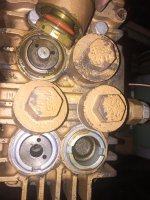
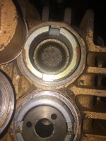
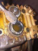
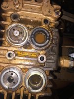
Thank you for the prompt information! I took off the valve covers today and see where the valve to the right of the unloader valve is black and covered in sut....it’s pretty nasty looking...I assume this is the “shot” high pressure valve? Anyhow, I’m wanting to rebuild this pump and having trouble locating the proper kit that looks like my valves. They all say 310-roc-20 and up but the valves don’t look like mine. So far I was only able to get out one valve on the low pressure side and it is a solid cast iron piece with a plate in the center with a spring under it I assume. Can I rebuild this valve or would you think it would be best to replace? It seems to be working properly, as far as for the others I’m not there yet because I haven’t figured out how to take out the round plate with the two holes on top of them? Any advice is appreciated. Thanks for the feedback. BTW that pool of liquid you see inside the valve is nut buster not oil.
 

Attachments

  • 0A01D45C-10D0-4BE6-9BE5-7917ADD4BA62.jpg
    0A01D45C-10D0-4BE6-9BE5-7917ADD4BA62.jpg
    123.2 KB · Views: 9
  • 4A17EB30-0F14-4627-98DB-222D7D16D054.jpg
    4A17EB30-0F14-4627-98DB-222D7D16D054.jpg
    117 KB · Views: 7
  • 1FA52A09-9893-4FE4-80B9-AF1370ED00FD.jpg
    1FA52A09-9893-4FE4-80B9-AF1370ED00FD.jpg
    102.7 KB · Views: 6
  • 695B1A3F-6C75-47F9-9AEB-ECA2786DCA32.jpg
    695B1A3F-6C75-47F9-9AEB-ECA2786DCA32.jpg
    135.2 KB · Views: 9
  • BEE7B785-6DD3-4387-BD06-B438147BD42F.jpg
    BEE7B785-6DD3-4387-BD06-B438147BD42F.jpg
    75.1 KB · Views: 7
Last edited:

MacMcMacmac

Well-known member
Joined
Oct 21, 2014
Messages
1,605
Location
canada
Depending on how much you want to spend you might be better off putting new valves in there. Probably wont be cheap. If you have a way to lap the seating ring on the valves while keeping them nice and parallel you can try that as well. I think these are the type of valves that are pressed together, with a small disc and spring riding inside the cast iron body. These discs are kept centered by their outside edge running against the valve body. What can happen over the years is that the disc wears away the inner surfaces of the guides and the disc can start to run off center and not properly seal on the seat. It will contact the seat, but it will leave a tiny sliver of open area like a crescent that the air can come back through. There is no way to repair this unfortunately, so new valves are in order if that is the case. Be sure to carefully inspect the valve bodies to see if there is any side to side movement of the valve discs.

The valves themselves should pull right out once you take out the threaded locking rings. These can be a bear to remove. We used to have the proper ring wrench with two inside teeth to take these out. Sometimes you can put a small length of flat steel bar though the notches and twist on that. Try not to hammer the notches, as they distort pretty easily.

The soot is not unusual for a compressor that has been running hot, especially if it has been filled with motor oil.
 
Last edited:

Jvasquez82

New member
Joined
Sep 18, 2019
Messages
4
Location
Windsor Illinois
Thanks again for responding. I have came to the conclusion of just buying new valves...My next question is do I have to put the exact same valves back in or are their different updated valves for this unit? And I did have to get creative and fashion a tool just to unscrew the threaded rings around the valves...I used 22mm 1/2” impact socket that fit perfectly over the threaded ring and I grinned a notch out of the bottom of both sides and placed a square bit through the notches and put my impact on it and it took a good 30 seconds but it broke it loose, thank god...and yes I did kinda knick the threads a bit but hopefully I can just file those 2 threads down a bit, it only knocked the edge by the notch...So you did say those valves with the two holes should pull out after I unscrew the threaded rings? That’s what I was thinking...my only next issue is the tool I fashioned won’t work on those because the valves are in the way...I’m gonna have to once again get creative and make something that go’s over or around the valves...I noticed most kits come with new piston rings but no pistons? Can I reuse my old pistons assuming they are still in good shape and just slap new rings on them? Will I have to hone the cylinder walls first? Thanks again for all the feedback... I appreciate all the help I can get....
 
Last edited:
To avoid these ads, REGISTER NOW!
Top Bottom