To avoid these ads, REGISTER NOW!

Looking at picking up a Bridgeport mill

81turbota

Well-known member
Joined
Oct 29, 2019
Messages
260
Location
USA
Looks great! I polished my BP head when I rebuilt it. It will not stay shiny..dirty hands up there with the draw bar, drum switch, in your case changing belts. I give mine a quick polish every now and again but it dulls quickly. I would also like to hear other opinions on this.

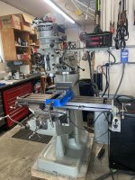
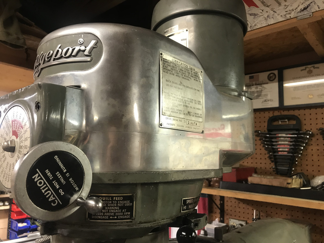
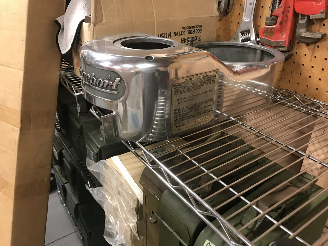
Then again I may be too picky. See for yourself, I just snapped this pic of the head uncleaned as it sits in this moment.

This is before and after about a year with a quick mother’s wipe every 4 months or so.

738584-E5-BEC9-415-A-A737-499-F06-DA562-F.jpg

DE2-D6-A3-C-B7-A0-4-D4-D-9916-3-DF3-D2999255.jpg
 
Last edited:
To avoid these ads, REGISTER NOW!

ClappedOutBport

Well-known member
Joined
Mar 30, 2016
Messages
998
Thanks for the advice. I’ll try to remember to tape the slit when running wood. One of my first projects when I get up and running will be to make a holder for the spindle to hold my festool vacuums nozzle. Hopefully that will cut down on the dust issues. I currently have a full festool woodworking system and I sure don’t miss the dust from my old tools!

If you intend to run a reasonable amount of wood, my advise would be to fab a router spindle holder to fit on the back of the ram. Then you'd keep your head cleaner and the RPM boost would be a major benifit.
 
OP
G

Grant Gunderson

Well-known member
Joined
May 17, 2013
Messages
2,318
Location
Bellingham, WA
If you intend to run a reasonable amount of wood, my advise would be to fab a router spindle holder to fit on the back of the ram. Then you'd keep your head cleaner and the RPM boost would be a major benifit.

That’s genius! Plus that way I can use the routers built in dust collection. Looks like I have enough clearance between the machine and the wall for it too. Thanks for the great idea!
 

gtr1999

Well-known member
Joined
Jun 25, 2012
Messages
151
Location
CT
Nice work. When we rebuilt them, we just wiped them clean as they were sent out to production use = back when we had factories in CT.
 
OP
G

Grant Gunderson

Well-known member
Joined
May 17, 2013
Messages
2,318
Location
Bellingham, WA
Got the quill pivot adapter off.
D1F4AC6D-3F72-4C5E-B395-033853B0FED2.jpg
It’s pretty crusty behind there. I doubt it’s ever been removed before but it should clean up nicely. The engine hoist I’m borrowing has too narrow of legs to pick the ram and turret by the standard eyebolt location.
Might try sliding the ram all the way forward and picking it by itself via a sling between the eyebolt and the hole in the back. We will see how it balances.

Got the table removed. There is more wear than I had expected on the ways. I don’t have the skills to hand scrape yet. Plus I’m probably more likely to make it worse than what slop it currently has. I’m sure the real machinists out there will rip me apart for not paying to have them scraped, but this is going to be a hobby machine and I’ll doubt I’ll have the skills to notice for some time. Plus if I ever get good enough where the ways are the limiting factor for the quality of parts I’m making then I’ll be able to better justify spending more coin on a newer machine. So thinking I’ll just clean them up and take a stone to them. I did that on the gibs and they cleaned up pretty well. There was more of the original hand scraping left on the gibs that I was only able to notice after I stoned them. So fingers crossed I’ll be presently surprised after cleaning the ways.
7D6C1D70-5AD2-4BFD-AD24-1A152F4F2F76.jpg

It’s amazing where chips can find there way to after 60 years! The knee was packed full of chips. I bet I pulled at least 10 pounds out of it!

I’m thinking of using a web sling around the internal casted cross brace to lift it. Thoughts? Seems like it would be more secure than trying to clamp a piece of steel in there.


688723A4-0FF0-4757-9CE0-7FE92FB55267.jpg
 
Last edited:

ClappedOutBport

Well-known member
Joined
Mar 30, 2016
Messages
998
Got the quill pivot adapter off.
D1F4AC6D-3F72-4C5E-B395-033853B0FED2.jpg
It’s pretty crusty behind there. I doubt it’s ever been removed before but it should clean up nicely. The engine hoist I’m borrowing has too narrow of legs to pick the ram and turret by the standard eyebolt location.
Might try sliding the ram all the way forward and picking it by itself via a sling between the eyebolt and the hole in the back. We will see how it balances.

Got the table removed. There is more wear than I had expected on the ways. I don’t have the skills to hand scrape yet. Plus I’m probably more likely to make it worse than what slop it currently has. I’m sure the real machinists out there will rip me apart for not paying to have them scraped, but this is going to be a hobby machine and I’ll doubt I’ll have the skills to notice for some time. Plus if I ever get good enough where the ways are the limiting factor for the quality of parts I’m making then I’ll be able to better justify spending more coin on a newer machine. So thinking I’ll just clean them up and take a stone to them. I did that on the gibs and they cleaned up pretty well. There was more of the original hand scraping left on the gibs that I was only able to notice after I stoned them. So fingers crossed I’ll be presently surprised after cleaning the ways.


It’s amazing where chips can find there way to after 60 years! The knee was packed full of chips. I bet I pulled at least 10 pounds out of it!

I’m thinking of using a web sling around the internal casted cross brace to lift it. Thoughts? Seems like it would be more secure than trying to clamp a piece of steel in there.


I would strongly recommend pulling the tilt from the head and inspecting that gear. It's a weak one. If it's bad on one side you can flip it 180 degrees and put the less worn side up. Also, the shaft that the worm sits on on early ones only extends the length of the worm, but on the later ones the shaft is longer and goes into a reamed hole past the worm. We modified ours and used the upgraded shaft.

Don't worry about the wear. I've made good parts on hilariously worn machines. You learn to work around it. It's still a very useful tool even in awful shape. If you have any flaking left at all it'll be fine for most home shop stuff.

I think we lifted with a clamped bar, I can't remember.
 
Last edited:

MushCreek

Well-known member
Joined
Jan 14, 2015
Messages
9,747
Location
Upstate South Carolina
Scraping machine ways takes a very high level of skill and experience. It also usually takes a of of equipment that you likely don't have. Paying a shop to do it is ridiculously expensive. I've done a bit of it over the years, and it's a slow, tedious process. I agree that you should be able to do OK work even on a sloppy machine.

I had a WWII vintage LeBlond lathe that I rebuilt. I was using it as-is, and decided to take it apart and do a rebuild. I had a shop with a shaper take the bed down to get it closer. They had to take .035" off to get it straight! Even from there, it took a lot of work to finish it up. All of the wear was in the typical area that a lathe gets used. The point is- it was capable of reasonable work even with all of that wear.

I've also done a 'light' rebuild on a surface grinder. The ways were out about .003", a huge amount on a precision machine. I was able to get it down to .0005" in a couple days work. Not perfect, but 6 times better than it was. I improved it by just focusing on the high spots, where it didn't have any wear, taking them down to the lowest point. I did sloppy work, so the 'rebuild' wouldn't have lasted as long as a good proper fitting, but it got me where I needed to be.
 

matt_i

Well-known member
Joined
Mar 14, 2008
Messages
10,723
Location
SE Michigan
Personally I think you'd be farther ahead by making an oil pump gun (modify grease gun) to oil the ways. OR...even better, put in a 1-shot lube system (Bijur, etc) that's going to oil the screws/nut as well as the ways.

A thing about scraping...you are taking material away/down. Suppose you have a surface plate and spend a lot of time improving the contact on only the flat. Now the table sits lower relative to the saddle and the screw/nut is now in a bind because the nut didn't move down the same amount. This concept is pervasive thru mills, lathes, etc. You need to make cast iron scraping masters and scrape those in to contact with the surface plate so you can print the dovetails, and eventually use the saddle to print the table dovetails. While scraping for contact you have to maintain dimension across. You have to straighten the gib. One tiny stupid chip or burr you forgot to wipe off the surface plate can send you in the wrong direction because now the part is printing incorrectly.

Its a cool thing to think about and try, but a machine is beyond most people's ability to put in Time, sooooo many iterations. I'd recommend starting on something small like a compound slide for a lathe that you bought from ebay if you wanted to give it a shot.
 
OP
G

Grant Gunderson

Well-known member
Joined
May 17, 2013
Messages
2,318
Location
Bellingham, WA
Thanks guys. Definitely not scrapping the ways. I’d like to learn how to scrape at some point but a milling machine ain’t the place to try it for the first time.


The rest of the parts arrived for the quill.

93ADDFFD-0907-492E-BC3E-C6E7987D1AB6.jpg

So got it and the gear housing fully reassemble.


C57D1432-3ABD-4D25-B83D-39B5284CD86C.jpg

3D299150-986C-41E1-8C3C-8DB91EBE351F.jpg

Got the bracket for the table nuts out. That X feed adjuster sure doesn’t look right!

BADAB1CE-F84A-44B9-BBF0-FE29A174BA81.jpg

Looks like the housing broke so they just packed a bunch of washers in there. Going to see what happens when I install the correct bolts and new nuts. Speaking of nuts the machine had one of the original non split nuts. Comparing it to the replacement I ordered I’m 99% sure all of the backlash was due to the nuts and not the screw. The brass threads where worn down to be almost paper thins while the screw threads don’t show any significant wear.

1EC02EA8-07C9-4D74-89B6-27D8026A3F1B.jpg

I haven’t decided on replaying the Y but yet but leaning towards it. Bigger issue is the damn adjuster bolt is fully seized. Tried PB blaster and a blow torch but no luck yet.


019B805A-86C7-49F6-8AFC-05A89B9635D1.jpg
 

ClappedOutBport

Well-known member
Joined
Mar 30, 2016
Messages
998
Head is looking great!

Again, if you don't replace the nut, I recommend sawing it in half to get your adjustment back. I'll have to see if we have a spare half nut holder if you need one, we scrapped one of these mills.
 
OP
G

Grant Gunderson

Well-known member
Joined
May 17, 2013
Messages
2,318
Location
Bellingham, WA
Head is looking great!

Again, if you don't replace the nut, I recommend sawing it in half to get your adjustment back. I'll have to see if we have a spare half nut holder if you need one, we scrapped one of these mills.

Thank you!

I’m really happy with how it’s all turned out so far.

Going to attempt to get the ram off today. The hoist I’m borrowing doesn’t have the reach to lift the ram and turret straight up so going to see if I can slide the ram forward and pick it separately.

I’m going to replace both nuts with new. I figure after 56 years of use they’ve earned their retirement. Plus anytime I try to skimp on something it bights ne in the *** latter so best to do it now while the table is off.
 
OP
G

Grant Gunderson

Well-known member
Joined
May 17, 2013
Messages
2,318
Location
Bellingham, WA
Been busy stripping all of the main body components for paint. The hoist I’m borrowing just doesn’t have the reach to remove the ram or knee safely, no matter how creative I get with webbing so it’s all getting painted in place.

Here is a comparison between the new nut threads and the old worn ones. 5FDB0A41-4C39-4E62-85EA-78DF1E25CD80.jpg

DA290989-E95E-479F-9EB0-DC2FEBCD6030.jpg

Not much of the threads where left on the original ones!
 
Last edited:
OP
G

Grant Gunderson

Well-known member
Joined
May 17, 2013
Messages
2,318
Location
Bellingham, WA
That's what they're designed to do. Hopefully, the threads on the leadscrew are still decent?

The screw threads appear to be in good shape. The new nuts feel pretty good on them. Curious to see how much backlash I have once it’s all assembled.

Took a break from paint stripping to organize some of the tooling.

First drawer is endmills ⅛ to 7/16
58B8619F-6B59-4FA1-A556-7180DFA1AF14.jpg

Second drawer is reamers, countersinks, misc drill bits etc.
49CC4D98-456D-4316-B6BD-0986B2F71FE2.jpg

I still need to organize the ½ to 2 inch endmills, all of the drill bits and the misc tooling and tool holders. Thinking of picking up some of the bigger HUOT drill index drawers as the mill came with a full set of drills from 1/16 up to 1 inch. Many of which where unopened Triumph drills.

Luckily it came almost fully equipped with mostly new unused tooling. Main items I’ll need to purchase to get going is a good test dual indicator and mag stand, a good set of parallels, and maybe a surface plate and gauge. Been keeping an eye out for used ones but seems most guys are asking new prices for 50 year old tools.
 
OP
G

Grant Gunderson

Well-known member
Joined
May 17, 2013
Messages
2,318
Location
Bellingham, WA
Finally got it all painted! That was one hell of a job stripping it all, getting it cleaned, fixing the body filler over the cast iron, but man am I glad I took the time to do it. I used successive grits of sand paper all the way up to 4000 on the areas where the mill is bare metal. IE the turret gauge. Obviously I left all of the ways alone other then cleaning them up with degreaser and a stone.


Going to give the paint a couple of days to cure then do the assembly.

9DC7B3F5-B7A1-4E56-857B-6D0701FD9AE5.jpg

Underside of table
9053A887-56EB-42F9-A304-494D61BC4B20.jpg

Underside of the saddle
3275D419-B366-4CAF-8461-42DF7DFF0C40.jpg

Turret Gauge. It’s a mirror!
D5DEF1FB-0941-475D-B4F6-86A6B50882DC.jpg
 
Last edited:
To avoid these ads, REGISTER NOW!

OccupantRJ

Well-known member
Joined
May 15, 2009
Messages
10,959
Location
Eastern North Carolina
Looking great there! I just started on one for myself to use out of 3 that I had around the shop. It will take me a while though, as I keep at least 3 refurbs going on at the same time to keep from getting bored on just one. My sons hangs out in the shop on some Saturdays so I put him to work.
 

Attachments

  • 3CDF873B-B156-4B48-9D2A-692C7A3223ED.jpg
    3CDF873B-B156-4B48-9D2A-692C7A3223ED.jpg
    94.4 KB · Views: 68
  • 2F37200F-9681-4376-89CE-C3303E3BEE91.jpg
    2F37200F-9681-4376-89CE-C3303E3BEE91.jpg
    89.1 KB · Views: 74
OP
G

Grant Gunderson

Well-known member
Joined
May 17, 2013
Messages
2,318
Location
Bellingham, WA
Well, its mostly done. Other than a miss hap ordering the correct feed nuts (I accidentally ordered two sets of the cross feed nuts so waiting on the x-nuts to arrive) its pretty much done. I used a blueing agent on all of the hardware to bring back the original black finish. Pretty happy with how it turned out. Just got to wire it once I get some time off from my day job.

IMG_0341.jpg

IMG_1200.jpg

IMG_1206.jpg

IMG_1208.jpg

IMG_1204.jpg

IMG_1211.jpg

IMG_1189.jpg
 
OP
G

Grant Gunderson

Well-known member
Joined
May 17, 2013
Messages
2,318
Location
Bellingham, WA
Looking great there! I just started on one for myself to use out of 3 that I had around the shop. It will take me a while though, as I keep at least 3 refurbs going on at the same time to keep from getting bored on just one. My sons hangs out in the shop on some Saturdays so I put him to work.

Nice! My son loves being in the garage but at 2 years old, he may cause more destruction than he "helps" but he means well.
 

ClappedOutBport

Well-known member
Joined
Mar 30, 2016
Messages
998
Looks great! I guess the Alamite fittings are yet to come. Have you converted a grease gun yet? :p
 

HotWire

Well-known member
Joined
Mar 21, 2010
Messages
368
Location
Montana
Awesome work! I’m super jealous as a Bridgeport is my next large purchase and there’s nothing in my area. I do miss some things about the hub of industry that is the MidWest!


Sent from my iPhone using Garage Journal
 
OP
G

Grant Gunderson

Well-known member
Joined
May 17, 2013
Messages
2,318
Location
Bellingham, WA
Looks great! I guess the Alamite fittings are yet to come. Have you converted a grease gun yet? :p

I added the oil lines for the nuts. On the fence about doing the entire one shot lube system. Seems way overpriced for what amounts to compression fittings so trying to decide on zerks vs building my own lube system.

Looks fantastic, great job!

Thanks really happy with how it turns out. Need to get power wired to it and put an indicator on it still to confirm that I didn’t just put lipstick on a pig. Problem is I’m back at the day job pretty much full time till April so we will see when I get some free time to do it.
 
Last edited:
OP
G

Grant Gunderson

Well-known member
Joined
May 17, 2013
Messages
2,318
Location
Bellingham, WA
After being on the road for work the last 6 months I finally had time to install a sub panel and run power to the mill. I also built a new control box for it as well as fully restored the Kurt vice that came with the mill. Im no electrician, but figured 8 guage THHN wire feeding the sub off of a 50amp breaker in the main box should be adequate. The VFD is fed by a 240 15 amp breaker off of the sub. The VFO is wired directly to the mill via a 3 phase 20 amp wall plug ( in case I gotta move the mill around).

I’ve powered it up and have even made a few chips with it. Everything works great! Well except for the DRO. The x axis works but there is zero readout on the Y axis. I’m pretty sure it’s the pickup on the scales. Since this DRO is pretty much an antique I’m thinking it’s best to scrap it. Anyone have any advice on a new replacement? As much as I hate stuff from China the price of new 3 axis units on amazon and eBay look like they could be the ticket. It’s not like I’m going to be using this to make airspace parts. I am fully capable of doing it the old fashion way with the dials on the table but the working X axis has me spoiled! I am also considering converting the mill to do both CNC and manual are some point so it would be great to get something that will work with a CNC controller setup down the road.
 

Attachments

  • CF308BD0-93C0-4080-8C40-7344189A30C9.jpg
    CF308BD0-93C0-4080-8C40-7344189A30C9.jpg
    111.3 KB · Views: 74
  • 0F8BC7B5-A9E6-40BA-950A-976179E62918.jpg
    0F8BC7B5-A9E6-40BA-950A-976179E62918.jpg
    116.9 KB · Views: 76
  • 8D452E82-8D08-4E92-A52B-369DB3950082.jpg
    8D452E82-8D08-4E92-A52B-369DB3950082.jpg
    135 KB · Views: 98

Robert Haas

Well-known member
Joined
Sep 30, 2010
Messages
1,749
After being on the road for work the last 6 months I finally had time to install a sub panel and run power to the mill. I also built a new control box for it as well as fully restored the Kurt vice that came with the mill. Im no electrician, but figured 8 guage THHN wire feeding the sub off of a 50amp breaker in the main box should be adequate. The VFD is fed by a 240 15 amp breaker off of the sub. The VFO is wired directly to the mill via a 3 phase 20 amp wall plug ( in case I gotta move the mill around).

I’ve powered it up and have even made a few chips with it. Everything works great! Well except for the DRO. The x axis works but there is zero readout on the Y axis. I’m pretty sure it’s the pickup on the scales. Since this DRO is pretty much an antique I’m thinking it’s best to scrap it. Anyone have any advice on a new replacement? As much as I hate stuff from China the price of new 3 axis units on amazon and eBay look like they could be the ticket. It’s not like I’m going to be using this to make airspace parts. I am fully capable of doing it the old fashion way with the dials on the table but the working X axis has me spoiled! I am also considering converting the mill to do both CNC and manual are some point so it would be great to get something that will work with a CNC controller setup down the road.


I started out with a cheap import DRO and it worked perfectly. In fact it worked way better then it should have for such a low price. However it had glass scales and they do not like to get wet and I use flood cooling often on bigger jobs so the DRO would go down at the worst possible times. Blow it out with air, and wait a couple days and it would come back to life.

Now have Magnetic scales and those days are gone.

If you are not going to get your scales wet and can keep your mill clean. Then go to Ali express and order a 300 dollar DRO and you will be fine.
 

zmotorsports

ALLIANCE MEMBER
Joined
Oct 20, 2009
Messages
21,327
Location
Northern Utah
Nice save and resto on the Bridgeport.

Out of curiosity, what size table? Looks like maybe a 9x42?

Sorry if you have already mentioned it. I looked back but couldn't find it on a quick glance.
 
Last edited:

ClappedOutBport

Well-known member
Joined
Mar 30, 2016
Messages
998
Well except for the DRO. The x axis works but there is zero readout on the Y axis. I’m pretty sure it’s the pickup on the scales. Since this DRO is pretty much an antique I’m thinking it’s best to scrap it.

I'm not sure if I would be quite so hasty to toss it. I used what I'm pretty sure is the exact same DRO at school for making a curve shape in the bottom of a pocket via "kellering" and I really liked the response time and refresh rate of that DRO. It was second only to an analog scale. I've got a Newall at home which is sort of the industry standard, but it feels like it had a bit more lag than that one.

But yeah, to echo the others the mill looks great.
 

matt_i

Well-known member
Joined
Mar 14, 2008
Messages
10,723
Location
SE Michigan
Potentially one could swap the X and Y inputs to the DRO control and see if that makes a difference. At least it will tell you if its the scale or the controller. This is assuming the connectors are identical.
 
OP
G

Grant Gunderson

Well-known member
Joined
May 17, 2013
Messages
2,318
Location
Bellingham, WA
So I finally got around to replacing the DRO. Ended up going with a 4 axis unit and am really happy with it!

I built a bracket so in addition to the Z axis on the Knee there is a U axis on the Quill. That is synced with the knees Z axis so no matter what one you move your overall verticle position is accurate.

I could have been a bit more precise with lacking the bracket but I figured it was ok for my eye balling the locations it needed to be in. I decided to try engine turning for the first time on the brackets since they are at eye level and am pretty happy how well the finish turned out.

Time to start working on some actual projects!

I’m still considering a CNC conversion for it but need to do a ton of research into that. Plus I haven’t used a CAD program in 20 years so trying to slowly teach myself fusion 360. Either I forgot a ton from when I used to use Catie and ProE or Fusion 360 is significantly different. I don’t know but it’s a bit of a challenge after a 20 year break from drawing.
 

Attachments

  • B8FFD5C0-CB79-42CC-B180-2C3A16E7A171.jpg
    B8FFD5C0-CB79-42CC-B180-2C3A16E7A171.jpg
    101.8 KB · Views: 79
  • EEE22403-487F-4DE2-80C9-F2C6860A5A67.jpg
    EEE22403-487F-4DE2-80C9-F2C6860A5A67.jpg
    107.2 KB · Views: 74
  • 33264449-5EAA-44F1-9191-A07200D64571.jpg
    33264449-5EAA-44F1-9191-A07200D64571.jpg
    139.8 KB · Views: 72

matt_i

Well-known member
Joined
Mar 14, 2008
Messages
10,723
Location
SE Michigan
I’m still considering a CNC conversion for it but need to do a ton of research into that.

Imo much easier to start with a machine that was purpose designed as a CNC.

Look for linear rail Fadals, VMC-15, -15XT and VMC-40s. Even those first generation 1980 technology "light duty CNC" machines will run circles around Bridgeport when it comes to actual milling. 88HS control is so easy to use, it was setup so that aging manual-trained toolmakers and machinists could make the jump to "control". Its likened to a Chevy 350 V8 engine. Simple and lots of parts are available. In any case a bed-mill configuration is much preferred to a knee mill.

Great job on your machine BTW, looks spiffy :thumbup: Time to start making some chips!!! :bounce:
 
To avoid these ads, REGISTER NOW!
Top Bottom