To avoid these ads, REGISTER NOW!

magnetic starter

lance8614

Active member
Joined
Dec 14, 2014
Messages
32
I'd appreciate help with wiring a mag starter, it's an older Furnas three phase which I want to use on a single stage Baldor 5 hp motor (for air compressor) The label inside the mag starter case is faded and torn, but it looks like the pressure switch should be wired to terminals 2 and 3 (?) Terminal 3 is wired to terminal V on the coil and terminal 2 is by itself. I was planning to use LI and L3 for power input and T1 and T3 to the motor. Does this sound right?

Also, the existing 220 line in the garage has me a little puzzled. I see that the ground wire is hooked up to the neutral bar in the panel instead of the ground bar...does this make any difference? The 220 line seemed to work fine with my old smaller compressor that did not use a mag starter (had built in overload protection) Any comments or suggestions would be much appreciated!
 
To avoid these ads, REGISTER NOW!

EricP

Well-known member
Joined
Jan 30, 2014
Messages
136
Location
Alabama
Most of my machinery is equipped with Gould/ITE starters but in general when using a three phase starter for a single phase motor double check the coil voltage before wiring the coil for 240. If your lucky it is a dual voltage coil that can be wired 240. Also double check the heater amperage vs. the motor FLA. Unless you are really really lucky you'll need to change heaters to prevent the contacts from opening when they shouldn't or even worse smoking the motor. You might search ebay for a picture of your starter that has a label you can read.
 

skruft

Well-known member
Joined
May 9, 2011
Messages
759
The 240 ground should be concerted to the ground bus, but it will function anyway.

The comment before this sets out the issues correctly. It is no problem to use the starter if you can produce the correct coil voltage.
 

Labradorian

Well-known member
Joined
Nov 5, 2013
Messages
315
Location
Pembroke, ON
I'd appreciate help with wiring a mag starter, it's an older Furnas three phase which I want to use on a single stage Baldor 5 hp motor (for air compressor) The label inside the mag starter case is faded and torn, but it looks like the pressure switch should be wired to terminals 2 and 3 (?) Terminal 3 is wired to terminal V on the coil and terminal 2 is by itself. I was planning to use LI and L3 for power input and T1 and T3 to the motor. Does this sound right?

Also, the existing 220 line in the garage has me a little puzzled. I see that the ground wire is hooked up to the neutral bar in the panel instead of the ground bar...does this make any difference? The 220 line seemed to work fine with my old smaller compressor that did not use a mag starter (had built in overload protection) Any comments or suggestions would be much appreciated!

1. As someone mentioned earlier, you need to know the coil voltage and can only use that voltage on the coil.
2. To be a starter, there are overload relays attached to the load side of the contactor? or is it just a contactor only. see pics would be nice.
3. If it has overload relays, they are sized or adjusted to the attached load.

If you have a contactor with overload relays, connect your motor circuit 220 to L1 and L2. jumper T2 and T3 together, and then connect the motor to T1 and L3.

If it is just a contactor without any overloads, what you said is correct, you only need to use 2 poles of the 3 pole contactor, L1, L2 and T1& T2 or L1, L3 and T1, T3 or L2, L3 and T2 and T3, for that mater.

With some starters(with overloads) the 3 overloads need to see the same current, not sure if this one has electronic or thermal overloads. no pics.

I can't confirm your coil connect terminals with out model # or pic.
just my 2

cheers
 

C96

Well-known member
Joined
Nov 30, 2013
Messages
1,251
If you have a contactor with overload relays, connect your motor circuit 220 to L1 and L2. jumper T2 and T3 together, and then connect the motor to T1 and L3.

If you have a contactor with overload relays, connect your motor circuit 240 to L1 and L2. jumper T2 and L3 together, and then connect the motor to T1 and T3.

I changed it thinking this is what you actually meant since this is how it is normally done (although both ways will work). ;)
 

metalmagpie

Well-known member
Joined
Nov 1, 2011
Messages
799
Location
Seattle
You want to look up how to run a motor in jog mode. The pressure switch closes, the motor runs. When it opens, the motor doesn't. No latching. This means that the pressure switch should bring power to the mag switch's coil. Hope that helps.

metalmagpie
 

Cyberbear

Well-known member
Joined
Nov 23, 2013
Messages
1,524
Location
California
Operating coil voltage is important , especially when determining the control voltage for your motor starter. You have not mentioned whether or not your unit is in it's own enclosure and if it has start/stop buttons installed in your enclosure.
You may wish to try using 120V on the coil before going to the 220V line voltage as your control voltage. There may even be a chance that the unreadable coil is made for 440V, but these are not usually found. These are simple units to hook up but a few important facts need to be verified before doing so. Ebay is a good place for motor control components.
 
OP
L

lance8614

Active member
Joined
Dec 14, 2014
Messages
32
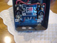
Re: mag starter, thanks to everyone who replied. I am attaching some images. The starter is a Furnas model D 15808. It has a dual voltage coil. Also has two heaters marked H-43, which are rated at 23.1 amps minimum and 26.1 amps maximum. The motor I am using is a Baldor rated at 20.6 amps with a service factor of 1.15. The mag starter came with the compressor and had been running it in a body shop for the last 20 years or so....the only difference is that the previous owner was using a bigger (215T frame) motor that drew 26.4 amps. He had disconnected the mag starter said he knew nothing about how to wire the pressure switch or anything else

The only thing that makes sense to me is to wire it to terminals 2 and 3 (?). Terminal 3 is wired to "V" on the coil and terminal 2 doesn't look like it goes to anything else. Again, any suggestions or comments are much appreciated! Lance
 

Attachments

  • mag 001.jpg
    mag 001.jpg
    127.2 KB · Views: 49
  • mag 002.jpg
    mag 002.jpg
    129.9 KB · Views: 42
To avoid these ads, REGISTER NOW!
OP
L

lance8614

Active member
Joined
Dec 14, 2014
Messages
32
Forgot to mention that the coil is for either 120 or 220 volts, currently hooked up for 220
 

C96

Well-known member
Joined
Nov 30, 2013
Messages
1,251
That thing is old. I personally would get a new one sized appropriately for the motor being used.

But, if you insist on using it, it looks as though by connecting the wires as such would enable it to work along with the pressure switch. The heaters and interior wiring should be changed to meet the new motor current, preferably THHN.

Also, don’t forget to ground everything properly!!

Good Luck! :thumbup:

Mag%20Start_zpssnwxdrng.jpg
 

EricP

Well-known member
Joined
Jan 30, 2014
Messages
136
Location
Alabama
That thing is old. I personally would get a new one sized appropriately for the motor being used.

I wouldn't replace it. With the proper heaters I fully expect it will outlast the newer IEC starters with their smallish contacts, especially given the current inrush of a compressor motor and number of start/stop cycles a compressor can see.

What NEMA size is the Furnas? I have a single phase baldor 5hp and from the factory it came equipped with an oddball NEMA size 1 1/2. NEMA size 1 for single phase motors at 240 is good up to 3hp.
 
Last edited:
OP
L

lance8614

Active member
Joined
Dec 14, 2014
Messages
32
Thanks so much for taking the time to help....what gauge THHN would you suggest to replace the interior wiring? It looks like the current wiring is 8 ga (?)
 

C96

Well-known member
Joined
Nov 30, 2013
Messages
1,251
If #8 then your good to go… provided the insulation is in good shape. It’s hard to tell what’s going on in there with the quality of the pictures. Even #10 should be ok.

The control wiring to the pressure switch and back to the coil can be smaller, #14 is quite typical for control wiring.

Have fun!
 
OP
L

lance8614

Active member
Joined
Dec 14, 2014
Messages
32
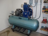
Many thanks to C96 and everyone else who replied...the compressor is running great. It is a Quincy 325 circa 1968 that I hauled out of a junkyard and rebuilt. It holds a steady 20 lbs oil pressure and pumps air from 0 to 180 psi in about six minutes. But when it stops there is no unloading. When running, there is no air coming out of the upper (D) port on the hydraulic unloader. But even without air pressure on the diaphragms it still pumps air, which I don't understand. I guess I will pull the unloader towers off and double check that I have it all assembled correctly. If anyone has any thoughts or suggestions I would much appreciate them. Thanks again..Lance
 

Attachments

  • comp 004.jpg
    comp 004.jpg
    126.4 KB · Views: 27
  • comp 006.jpg
    comp 006.jpg
    128.5 KB · Views: 34
OP
L

lance8614

Active member
Joined
Dec 14, 2014
Messages
32
I think I may have that backwards. Shouldn't there be air pressure on the diaphragms only when the compressor is not running and there is pressure in the tank? Then when it starts and oil pressure is up to 15 or whatever, the hydraulic unloader should shut off air delivery to the diaphragms and allow the unloader valve to seat? I looked at my hydraulic unloader and it is stiff, the plunger does not go in and out without a lot of force, and certainly doesn't close against the spring like it should.

Does anyone have experience with rebuilding these units, or should I just bite the bullet and get a new one for $120 or so? I thought about soaking it in carb cleaner or other solvent overnight (minus the o rings) to see if it will free up. My compressor seems to work fine but I am trying to avoid excessive strain on the motor at start up. When the tank has some pressure in it I can't turn the flywheel by hand. Thanks again.
 

C96

Well-known member
Joined
Nov 30, 2013
Messages
1,251
Nice Job on the compressor rebuild. looks sweet! :beer:


The color of the tank looks like the genuine Saylor-Beall color…Lol…I like it :D

Oh, by the way, welcome to this great website :thumbup:
 
To avoid these ads, REGISTER NOW!
Top Bottom