To avoid these ads, REGISTER NOW!

Major problem with Bendpak lift installation - need engineering help for a solution

dipan

Well-known member
Joined
May 24, 2012
Messages
178
Location
South Texas
I know not everyone here is an engineer, but there are some seriously smart guys on this forum when it comes to this stuff.

So here's the problem. I was sooo excited a few weeks ago because my new Bendpak XPR-10A lift was being installed by a local pro in a newly built man cave - garage mahal. Well they come out and are ultimately unable to install the lift. The problem is that the ceiling recess, which was supposed to be designed for this lift, and the engineered slab, which was also supposed to be designed for this specific lift, were both done wrong. I know I should go back to those people and point fingers, but I really want to just get this done. The slab issue is not a major one. The slab, even without the "engineered" footers-piers, is enough to handle the lift. Even as incorrectly "engineered" (I'm going to keep putting that in quotes until my faith in "engineering" is restored) the posts will still partly be sitting on the 2' deep piers. The whole slab is rebar reinforced every foot, 4K PSI, 4-6" thick.

The ceiling clearance is a major issue. The ceilings are 10' with the raised area over the lift recessed into the attic space above by 2' for a total of the needed height clearance for the lift. Unfortunately, someone 'decided' that 10' was wide enough for the width of the recess. The lift specs (which I had given to the builder before construction began) indicate 132" for the "narrow" configuration and 145" for the "wide" configuration. I was hoping for the wide configuration, but neither will fit in the 120" of space built.

Here is my build thread that I sporadically update for some more details and pics of the basic setup:

http://www.garagejournal.com/forum/showthread.php?t=195630

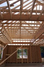
Following is a picture of the sad sad lift sitting gathering dust on the side near the lift location. Note the ceiling recess described above:


A closer view of the recessed area in the ceiling:


A closeup of the area that needs to be cut out in order to accommodate the lift post follows. Of course, there has to be a major intersection of serious laminated support beams in just the right location. There is a long triple 2x18 laminated beam there running alongside the recessed area and a double 2x16 laminated beam meeting it at a T. There is a second story but not in the location of the beams in question and not over the lift:


The builder and framer have been at work trying to devise a solution and they have turned to a combination of 1/4" and 3/8" steel plate. They plan on buttressing the joint with steel plate that is welded together, saddling the cutout region, then cutting out the square area needed for lift post clearance. They have asked if it's okay that a post is placed there and I replied that I don't really want the post. This was intended to be a wide open space and I want it to try to stay that way. Plus, if I wanted to ever use the space for something else down the road (don't see that happening) it would be nice to not have a post in the middle of the room. That said, if I have to have a steel post to support the joint, it shouldn't be in the way too much as it would be pretty close to the lift post anyway, just outside it.

The lead framer has made a small steel scale mockup of a potential solution:


The way I see it that open-ended steel U (this is the thicker 3/8" plate) is all that will be keeping the intersection from sagging without the help of the steel post. If steel plate is added to the entire top of the structure, effectively completely encasing the beams and covering the top of the steel U section should seriously increase rigidity and hopefully a support post will not be needed.

Please, any and all thoughts are welcome ...
Even if you just want to call me out as a ******* for not measuring the width during framing stage...... :withstupi :lol_hitti
 
To avoid these ads, REGISTER NOW!

tc-cad

Well-known member
Joined
Jan 15, 2012
Messages
270
Location
Mequon, WI
Can you mount the two post lift closer together to accommodate the 120" opening. I know that the lift was designed for the 132" opening but i see no reason that it can't be modified to fit the 120" opening. Is it a floor plate model or over head model? I think you only need to shorten the chain and the covering plate to make this work.

TC-CAD
 

tc-cad

Well-known member
Joined
Jan 15, 2012
Messages
270
Location
Mequon, WI
Are the posts actually taller than the lowered ceiling? Can you exchange the lift for a floor plate model? Usually the only need for the opening in the ceiling is the car itself not the lift.
 

jlckmj

Well-known member
Joined
Dec 7, 2009
Messages
732
Location
SE Wiscosin
If you gave them the spec's and they decided not to follow them, it is up to them to make it good.
i just hope you don't end up with less than sufficient framing when they are done. I would require an engineer sign off on the changes to those micro lams.

Jim
 

Shadowdog500

Well-known member
Joined
Dec 7, 2009
Messages
9,832
Location
Down the shore
Beautiful shop!!! With the money you must have in that place I wouldn't settle for a half assed fix. It would bother you forever.

673c91d53bc965c5c0d3b8c6a68b6d57_zpsb836b14b.jpg


62420e82c3341ffa9ad46e6c7573b635_zps93fc46cd.jpg


I see you can easily move the other side but I wouldn't get too close to the wall.

Chris
 
Last edited:
OP
D

dipan

Well-known member
Joined
May 24, 2012
Messages
178
Location
South Texas
I don't know if the posts can be mounted closer together or not. But I don't think I should have to compromise to get them even narrower than the suggested narrow configuration.

Unfortunately I have already bought the lift after putting hours ... no ... days of thought into it, before, during, and after construction. I don't want to return it for another lift. I don't want a floor plate either. These are all different sorts of compromises.

Shadow ... I'm glad you brought those framing pics over here. This is what the attic space looks like over the area in question. I suppose the beam could be moved over the 15-18". I'm sure there's all sorts of electrical in the wall that could be redone if needed. I'm liking this solution. The other end of the triple lam is T'd into a quad lam as in the picture below.


jjpp

Well-known member
Joined
Mar 20, 2011
Messages
190
Location
michigan
According to the spec sheet the outside width of the columns is 128" when set to the narrow setting.
132" is the base plates on the floor.

Could you move towards the wall 8" to avoid the beam? You stand to gain at least an 1" by just removing the drywall. I know that there is a minimum space from the wall that is required but in the name of not re engineering the garage I don't see why it couldn't be fudged a little to maintain proper structure.
 

LennyTheLizard

Well-known member
Joined
Oct 25, 2010
Messages
325
Location
Southeast MO
Maybe I missed some details.

How tall are you 2 post uprights from floor to top? And is there a bar that connects the two posts at top?

Is the raised ceiling for the posts, or for the top of you vehicle?

The picture of bracket you show - I wouldn't do it. I would at least weld a plate on the bottom side of it (connecting all the "protrusions" together) and then run angled braces or gussets from your post to the edges of bracket.
 
OP
D

dipan

Well-known member
Joined
May 24, 2012
Messages
178
Location
South Texas
The one solution I have decided against is a new lift. I spent quite some time and effort into picking this one. Although that in-ground lift is cool, did I mention there are two 2x4x2' concrete piers in the ground. It would take a lot of work getting those out to install an in-ground lift.
 
OP
D

dipan

Well-known member
Joined
May 24, 2012
Messages
178
Location
South Texas
Maybe I missed some details.

How tall are you 2 post uprights from floor to top? And is there a bar that connects the two posts at top?

Is the raised ceiling for the posts, or for the top of you vehicle?

The picture of bracket you show - I wouldn't do it. I would at least weld a plate on the bottom side of it (connecting all the "protrusions" together) and then run angled braces or gussets from your post to the edges of bracket.

The two posts are 12' tall. There is a top plate at the top of the 12' posts.

The bracket does have steel plate along the bottom of each beam attachment. The top is open and that's where I proposed modifying the design by adding a plate to make it more rigid wherever possible. Adding a plate to the bottom of the open U would defeat the purpose of doing this in the first place. That area is needed to be clear and the whole reason this is being done.
 

jjpp

Well-known member
Joined
Mar 20, 2011
Messages
190
Location
michigan
By looking at the picture above it appears that you have the set back of the post at least 3ft from the wall. Moving 8in towards the wall won't kill the work ability of the space, remember the vehicle will still be at least 8-12in in from the inside of the post.
 

LennyTheLizard

Well-known member
Joined
Oct 25, 2010
Messages
325
Location
Southeast MO
I don't have much for sketching, but I meant like this.
 

Attachments

  • A0FF0C1A-C07C-4F8D-9F31-498260347E79-1002-000000CF010F6D4F_zpsb96a4725.jpg
    A0FF0C1A-C07C-4F8D-9F31-498260347E79-1002-000000CF010F6D4F_zpsb96a4725.jpg
    70.3 KB · Views: 193

38Chevy454

Well-known member
Joined
Dec 26, 2006
Messages
4,036
Location
Cincinnati, OH
Explain why you can't just move the lift over a bit? Even if it misses the concrete you poured extra deep, could you put some steel plate ( say 1 inch thick for example?) to spread the load? The steel plate can be mounted to the deep concrete portion for additional strength. Still use anchors in the orig lift base plate holes through the steel plate.

Then the lift posts could go right alongside the existing beams without having to move them. This seems so much easier then cutting the beams and rigging some fabricated bridge piece like you showed. Also easier than moving the beams now that it is all finished.
 

Midnight_America

Well-known member
Joined
Oct 19, 2012
Messages
228
Location
Northern Illinois
Any of the changes to the structure you've described would be, at best, a compromise that you'd probably regret. If you do go ahead with the changes, I'd have a PE design the change and then sign-off on it. That would cover you from a liability standpoint if the structure ever fails. PE's don't come cheap and you'd need to recoup that cost from the builder.
Whatever you do from this point on is a compromise, so why not compromise on the Lift and leave the structure alone. Because of its top beam, its 12-foot post height, and its minimum width requirements, the XPR-10 two-post lift is not going to fit without changing the structure...no way, no how. If you can live with an XPR-9, life would be great. The XPR-9's posts are just shy of 10 feet so that would alleviate your height problem. The XPR-9 has no top beam. That would allow your raised vehicle to utilize the "real estate" of the recessed area of the ceiling. You could even utilize the XPR-9's maximum width of 145 inches. Not to be rude, but you got screwed. I would not let the same guy that screwed me attempt to engineer the plan to somehow un-screw me. The "damage" is done...... so Please leave the structure alone and consider a different lift. I think that solution is a win-win for you and the "smartest" solution for all the involved parties. Now, as far as your compensation for being screwed is concerned, that's why there are lawyers and judges.
 
OP
D

dipan

Well-known member
Joined
May 24, 2012
Messages
178
Location
South Texas
Explain why you can't just move the lift over a bit? Even if it misses the concrete you poured extra deep, could you put some steel plate ( say 1 inch thick for example?) to spread the load? The steel plate can be mounted to the deep concrete portion for additional strength. Still use anchors in the orig lift base plate holes through the steel plate.

Then the lift posts could go right alongside the existing beams without having to move them. This seems so much easier then cutting the beams and rigging some fabricated bridge piece like you showed. Also easier than moving the beams now that it is all finished.

If I positioned the lift posts inside of the 10' recess, the space between the posts would be 12" narrower than even the narrow configuration. The concrete is not a concern. The concrete is good enough even without the piers. Just annoying that I paid for them but they won't be used.
 
To avoid these ads, REGISTER NOW!
OP
D

dipan

Well-known member
Joined
May 24, 2012
Messages
178
Location
South Texas
Before you get too far into changing stuff you might want to double check your actual overall height in the cut out area, because you said it was 10' plus 2' extra in the cut out section, but that is only 144" total and the specs for your lift show it being 145" total in height. Remember to also take into account any slope to your garage floor if there is any, as the columns may need a little bit of shimming to make them plumb.

In as far as the columns themselves is there any way yo can move them a little bit to clear the 2 beams? I would not cut the beams out or move them now. It would be a big hassle and it would most likely cost you more money than it would to instead cut and pour a new relocated concrete support pad under the floor.

By looking at the specs for your lift it appears that the cross bar that goes between the lift column will most likely run right over the top of your existing beams without having to cut them. You will just have to remove some of the fill-in blocking between the beam top and the trusses.

You should be able to leave the beam that runs the length of the garage stall, because the lift carriage is about 4' tall so there is no reason that the top couple feet of the lift column can't be almost enclosed in its' own little boxed out area on all 4 sides with only a hole in it for the cross bar to exit the side of the box to go to the other column. If all of this is possible you would only need to move a single ceiling joist which would be easy with simple joist box around the lift column just like you would do to install a 4' wide skylight on a roof when you have trusses 2' on center.

My picture shows what I am thinking. The red lines represent the existing beams.

If what I am suggesting can't be done I agree with everyone else and I would get another lift that works with the existing structure before I would start cutting into and altering the existing structure. That would just be a bag of worms and quite an added cost for an inferior final result.

Another great idea! Thanks so much ... The installer did think that there was enough clearance for the 145" height. We might have to trim a bit off the top of the laminated beams to clear the crossbar but that is a much better compromise than cutting the laminated T joint out.
 

DangerousDan55

Well-known member
Joined
Jan 11, 2013
Messages
180
Location
Hockley, TeXas
I believe that Jeremy hastheperfect solution! A friend of mine built a new house & his lift would have to go through the ceiling also. But on one side, the slope of the roof was too close with the rafters. So, he put in a dormer window on the roof. The window was blacked out so you wouldn't see the top of the lift. He also trimmed out the holes in the ceiling. Looks Very good! Great input Jeremy!
 

bighead51

Well-known member
Joined
Feb 13, 2012
Messages
52
Location
Hunt County,Texas
why hasn't anyone thought about it from the stand point if it was your own? He gave the builder the correct size needed for the lift and had it engineered so it would work. The framers didn't frame it correctly! They have to tear it out and do it right or have a engineer come up something that will pass all codes!! Its all on them not the owner !!! I know its a lot of work but by all means get what you paid for!!!!!!!!!!
 

MackMan

Well-known member
Joined
Jul 25, 2012
Messages
648
Location
Lexington, NC
While it seems there are some good solutions provided here, but was the dimension of this cutout ever specified? You said you provided the lift specs to the builder and perhaps that is enough but I don't know if all builders are familiar with that type of thing to know what to look for. It just seems to me like if this was fully specified the way it turned out would be a breach of contract.

I have to admit though... I've seen a few people that put the lift columns going into the ceiling like what has been suggested, and it looks pretty cool, so if that works for you I don't see why not.
 

HoosierMark

Well-known member
Joined
Jan 31, 2013
Messages
1,440
Location
Southeast IN
I agree with bighead51. I read this post several times and keep coming back to the same thing. Did the builder build what you contracted for, if not then make him do it. Hold him accountable. Plain and simple, he made a mistake and needs to correct it. Yes it will take time and money but that is the risk you take when you are in business. Plus this is something you will live with the rest of your life, get it right the first time. If it was not specified, then go with one of the suggestions others have posted. You are only asking for what you had agreed to.
 

pattenp

Well-known member
Joined
Jun 4, 2008
Messages
10,175
Location
Virginia - USA
If it was me I'd re-box the left side ceiling and move the whole lift closer to the wall and not worry about the columns not setting on the piers. Then ask the builder to refund the cost of pouring the piers and also get some money compensation for the mistake. Other than that, tear it apart and get the builder to do it right.
 
OP
D

dipan

Well-known member
Joined
May 24, 2012
Messages
178
Location
South Texas
The builder is a great guy and I am fully committed to working with him. He has done an incredible job so far. He is a high end custom homebuilder and has not specifically built a home before with a lift specified. To his significant credit, he was assuming the fix would be on his own dime without me even asking. He also knows that I have pretty high standards. My beef is mostly with the architect and slab engineers. The architect should have made the recess big enough. How do you go about specifying a recess without knowing what it's for? I did give the spec to him and the architect and engineers had access to it. I believe the architect somehow specified the dimensions for the cutout (not sure how), and the slab engineers went off of those dimensions to beef up the slab.

So ... the framers built it to the architect's drawing. The engineers improved the foundation based on the architects drawing. 10' and 12' look pretty similar to me on a huge plan drawing, so I didn't catch it either.

My purpose for the post was not to assign blame though. It was to get help with a solution. To that end you have all been very helpful. I'm very thankful ...

The steel saddle solution probably won't work without a post, even with the great bracing options described.

Making the entire recessed area larger by moving the lams is an option but will probably cost a bit more, just because all the crews would need to come out again and redo a small area. I think I would be happiest with this solution, though, as it doesn't change the structure of the roof very much.

Recessing the top plate into the ceiling would necessitate an eccentric placement of the posts in the existing recess. While it seems like a reasonable solution, another thing I have to consider is the six floodlights recessed into the concrete (which I did not mention above). If I shift the lift off the center of the existing cutout, then the lights will no longer be centered.
 

MoonRise

Well-known member
Joined
Nov 5, 2010
Messages
4,028
Location
NJ
Hmmm, let's see now.

Builder and framer had plans that specified who/what/where/when/how to do the slab and piers and garage in order to accomodate a specific 2-post lift?

If (big if) the plans were correct and items (slab, piers, framing) were not made to those plans, then whoever did not follow the plans gets to remove and redo their work in order to meet those plans. (and that also means they get to pay for all the other trades to com in and redo -their- work as well).

I would NOT accept a 'builder' or 'framer' trying to half-a$$ some sort of 'bracket' in order to redo some major structural framing with engineered lumber.

The ONLY person who is acceptable to do a 'custom' engineered bracket and also verify all the structural loads with the 'redone' framing and bracket(s) is a LICENSED "Professional Engineer". Who will design and verify and "stamp" the bracket plans and construction details and the building plans with the redone framing.

A 'framer' is NOT a PE. He can -not- "design" a structure or bracket.

A 'builder' is not a PE (99.999% of the time). He can -not- design a structure, especially something with 'non-standard' structural framing.

IMNSHO, start at the bottom of the structure and go up from there.

Are the piers in the correct place for the lift? If no, saw cut the slab and pour piers in the correct place(s). Depending on placement and overlap with the existing piers, the 'new' piers may have to be anchored into the existing piers. If yes, proceed upwards.

If the piers are in the correct place (or are redone to be in the correct place), then is the framing in the correct place (according to the plans)? Obviously not. If the (original) plans (which were signed and 'approved' by whatever engineering and permitting personnel/groups were involved) had the framing in the corrrect place to accomodate the lift, then the framing MUST be removed and redone to conform to the (approved and permitted) plans.

Nothing more and nothing less.

Or if a different lift is 'acceptable' to the owner and will 'fit' the existing piers/slab/framing, then builder buys the OP's XPR-10A lift from him (at full cost that the OP payed, including tax, delivery, shipping and handling, everything) AND buys the replacement lift (as partial compensation for screwing up in the first place). Because it's either that or redoing whatever was done wrong in the first place (which will probably cost waaaaay more than buying a 'replacement' lift for the OP).

If the original plans were 'wrong', then that's a whole kettle of a different kind of fish.

Anything structural, has to be done according to the original approved plans or new approved (signed, stamped, and approved by a PE and by the locale's permitting/building departments) plans have to be made and then followed by the 'builder(s)'.

Again, nothing more and nothing less.
 

pattenp

Well-known member
Joined
Jun 4, 2008
Messages
10,175
Location
Virginia - USA
Are those for Vegas Night. :lol_hitti

another thing I have to consider is the six floodlights recessed into the concrete (which I did not mention above). If I shift the lift off the center of the existing cutout, then the lights will no longer be centered.
 

MoonRise

Well-known member
Joined
Nov 5, 2010
Messages
4,028
Location
NJ
OK, the OP posted a bit more explanation as I was typing my post.

The specs for the lift were supplied to the builder and thus to the architect. Architect made plans and framers followed those plans. But the architect didn't size/space the ceiling recess correctly (10 ft width as opposed to the 'correct' 12 ft width).

Not framers' fault. Not (directly) builder's fault. Architect's fault. Get architect (and thus his/her PE's) to figure out how to fit a 12 ft wide lift into a 10 ft wide recess.

Saw-cut slab and excavate in order to put piers where they are supposed to go for the 12 ft wide lift. Temporarily support ceiling and beams, remove the engineered beams and shift them over to make the desired/required 12 ft recess, make sure PE verifies beam placement and structural configuration as OK, resubmit plans to permitting office for re-approval (they'll most likely just check verify that a PE signed and "stamped" the revised plans). Reframe as per the revised plans. Install the BendPak XPR-10A and be happy. :D

IMNSHO. :beer:
 

JakeKohl

Well-known member
Joined
Feb 23, 2012
Messages
1,365
Location
Greenville, SC
I suspect that in all of the time it has taken to have all of these conversations, they could have reframed that ceiling and rearranged the beam with the proper dimensions. It's a PIA but it's the simplest and most complete fix.

The architect owes you the fix and it sounds like the builder might be amicable to the idea.
 

Texan1

New member
Joined
Oct 2, 2013
Messages
3
Location
Leander, TX
If it were me, I'd keep the lift centered over the recessed cans and have the ceiling framing reworked to get the clearances needed in both directions. Based on the pic in the framing stage, the left side of the pop up is just a furr down and is non structural. There appears to easily be 12"+ to be gained by reframing this side without getting into the rafters. That would put your lift post about 2' from the wall, but how often do you really plan on walking around it in that direction.
In looking at your slab rough-in pic, your lift footer goes to within about 12" or so of the side wall, so the left side of the lift should be fully bearing on it.
Shift your 3 ply lvl over 12"+ in the other direction and the tray will stay centered over the floor cans as you intended.
Even if the right side of the lift misses the footer, it appears that there is a grade beam in the slab right next to it that it would still bear on (assuming your rebar is appx. 12" o.c. in the pic).
That entire pop up will need to be re-rocked when done since you are going to need the small lvl beam on the end replaced with a longer one (possibly both ends depending on how the end not pictured is framed), and the ceiling joists over the pop up will need to grow as well, but that's not too much material and drywall repair is pretty standard and straight forward - certainly nothing your builder should balk at if he is accepting responsibility for the oversight in the first place.
If you do decide to relocate that 3 ply beam, I suggest making sure the framers put a new stud column in the exterior wall underneath the beam so the load transfers to the footer correctly, and check to be sure they re-brace the roof above back to the beam as it is currently before they close everything up and you lose visibility of it.
And please don't get talked into accepting a post in the middle of your space - you've already made a big investment in those large clear span lvl members and you don't want to loose that openness you paid for.
My .02 cents!
Best of Luck and keep in mind that while it may seem like a lot of work, it's only lumber and drywall, not really that big of a deal for a good builder and framer to fix it right.
Steve
 

Attachments

  • pop up ceiling.jpg
    pop up ceiling.jpg
    101.2 KB · Views: 102
  • cans in slab.jpg
    cans in slab.jpg
    145.1 KB · Views: 116

ZRX61

Well-known member
Joined
Aug 15, 2006
Messages
28,716
Location
Solar Blight Valley, SoCal
Looks to me like the fix will be on the architects dime? & also the builder if he had the correct specs & made a complete balls up of it.

If it were my place I just show him the specs & say "Here, this is what you were supposed to build, now fix it"... no matter how much of a good guy you think he is.
 

bazzateer

Well-known member
Joined
Oct 8, 2009
Messages
6,075
Location
Watford, Great Britain
Sorry but if the architect has got it wrong then it's down to him. Even if it means the rebuilding of the roof. His mistake, his responsibility, his cost.
 
Last edited:

Ign

Well-known member
Joined
Jul 7, 2006
Messages
12,769
Location
Butte Peak ND
{snip}
If you go this route one thing you will need to make sure of is that the openings for the columns are large enough so that you can successfully feed the columns up into them when setting the lift up for the first time. Because the columns are 12' tall and the ceiling height to the bottom of the new column openings would only be 10' you will have to slowly feed the columns up into the holes at an angle, so the holes will need to be larger than the columns in at least one dimension to allow for that.

And same principle on the cut-outs for the top bar and cables; give yourself enough room to comfortably reach in there and swing a ratchet, visually inspect the upper pulleys, etc.
 

tymbo

Well-known member
Joined
Apr 6, 2012
Messages
612
Location
West Chicago
Did the owner sign off on the final drawings? Did the drawings show the building section with the lift drawn in to scale? If not, why not?

I do engineering/shop drawings for large millwork jobs. When a piece of equipment is involved in our work, we will not proceed without written specs and dimensions of the equipment. It is MY job to make sure it fits into the design, or bring it to the attention of the owner/architect/general contractor.
Somebody dropped the ball in the design phase by not incorporating the dimensions of the lift into the drawings.
 

sabercatt

Well-known member
Joined
Mar 12, 2009
Messages
288
looks like the truss design puts load point on that beam. cant move beam without re-design of trusses. 4 post lift easiest solution.
 

lynnbilodeau

Well-known member
Joined
Jun 4, 2013
Messages
813
Location
Oklahoma
The other side would be easier to move.

How about this solution!

Image.ashx


http://www.automotivetools.com/Rota...e-Rise-71-1-2-inch/SL210-BUI/674/Product.aspx

Chris

Read this thread, and your build thread. ***** when things go wrong.

If it is on someone else's dime, I would do this. It has to be cheaper in the long run than reconfiguring the ceiling.... and you still won't have your piers where they should be, unless I read wrong.

I see no downside.

Besides, having worked for a living for 18 years using both in ground and above ground lifts, I can guarantee you will like the in ground much better.
 

Junkman

Well-known member
Joined
Dec 18, 2006
Messages
6,615
Location
Northeastern CT
............ My beef is mostly with the architect and slab engineers. The architect should have made the recess big enough. How do you go about specifying a recess without knowing what it's for? I did give the spec to him and the architect and engineers had access to it. I believe the architect somehow specified the dimensions for the cutout (not sure how), and the slab engineers went off of those dimensions to beef up the slab.So ... the framers built it to the architect's drawing. The engineers improved the foundation based on the architects drawing. 10' and 12' look pretty similar to me on a huge plan drawing, so I didn't catch it either.............................

You said it yourself. The architect screwed up, and that is why he has errors insurance... to pay for mistakes if and when he makes them. I would get an attorney involved, and have him send the architect a registered letter advising him that he made a mistake, and he is responsible for the cost of fixing the mistake. His insurance carrier will be paying for the PE to assess the damage, and how to correct the mistake. Like everyone has said, this isn't going to be cheap, but if it isn't corrected now, you will never be happy with the results later on.
When I was building my home, I found a mistake, and the framing crew foreman, said it is a small mistake, and that I should live with it. I said no way, and he replied that he wasn't going to fix it. I told him that he had a choice to either stop work immediately and leave the job, or to tear it out and fix it to conform with the plan. He and the rest of the crew walked off the job. I called my attorney, who called his boss, and explained what had happened. They were back there the next morning, and fixed the mistake. All too often, the people that are doing the work, have the attitude that they won't have to live with the mistakes, so there is no reason to fix them to satisfy the customer. The only thing that changes that is when you, the customer insist that it be done.
 
To avoid these ads, REGISTER NOW!
Top Bottom