r_olson_06
Well-known member
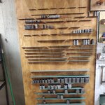
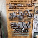
To add some content I wanted to post my process of building a new tool board to hold all of my Plomb sockets I have and the ones I am currently missing.
The Why:
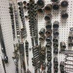
To pass some time and get organized a bit with my Plomb collection I have decided to put some effort to organizing my Plomb sockets. With my current peg board design there is not a great way to hang the sockets with existing hardware other hanging socket rails or individual sockets on pegs. This does not display them the best either showing the drive or socket end of the tools. Finding a way to display the sockets with stampings facing out would ideal for display and easier reference.
The Design Concept:
In order to display the stampings the sockets must rest on a shelf. I thought about using wood but thickness of the wood would take up alot of space so I started to look towards metal for the design as it has the strength needed to support the sockets without taking up a lot of space. Looking at options for metal I first looked towards angle iron but realized that different sized angles would be required for the various size of sockets. I could opt for a 4" angle shelf to cover everything but it would look out of place for the smaller sockets.
Kicking around some ideas I decided to go with a piece of flat steel cut to the crucial dimensions for each socket set. The flat steel would have several crucial dimensions for each set which includes width, and a tapered depth for each set. Here is the generic conceptual design for the shelves.
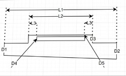
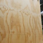
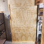
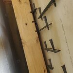
The concept of this shelf would be cut a slit into a piece of plywood allowing the D3 tab to be inserted into the slot in the wood. Once though the wood a couple of metal tapered shims would be put in the rectangular cutout to secure to the plywood from the back creating a floating shelf.
One of the time consuming challenges you could imagine was determining the proper shelf dimensions for each set. Since I didn't have all the sockets from each set I had to interpolate what the cruical dimensions of the set would be mainly the diameters of each socket. Since I have a pretty solid catalog of what sockets are in what sets I was able to find a correlation between socket size and OD (outside diameter) of each socket. Different series had different correlations due to the required wall thickness for the application. Using Excel I was able to find these correlated values then calculate the shelf crucial dimensions.
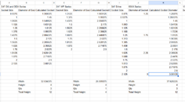
After calculating the size shelfs needed for each set I then built a table of data for each dimension that referenced the generic design. It turns out I need 49 shelves.
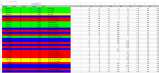
I then had these shelves CADed up and sent out to be cut out of 14ga steel.
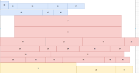
In the next post I will show you how I laid out the shelves and determined the best layout and size of board I need. Thoughts and feedback are always appreciated.
The Why:
To pass some time and get organized a bit with my Plomb collection I have decided to put some effort to organizing my Plomb sockets. With my current peg board design there is not a great way to hang the sockets with existing hardware other hanging socket rails or individual sockets on pegs. This does not display them the best either showing the drive or socket end of the tools. Finding a way to display the sockets with stampings facing out would ideal for display and easier reference.
The Design Concept:
In order to display the stampings the sockets must rest on a shelf. I thought about using wood but thickness of the wood would take up alot of space so I started to look towards metal for the design as it has the strength needed to support the sockets without taking up a lot of space. Looking at options for metal I first looked towards angle iron but realized that different sized angles would be required for the various size of sockets. I could opt for a 4" angle shelf to cover everything but it would look out of place for the smaller sockets.
Kicking around some ideas I decided to go with a piece of flat steel cut to the crucial dimensions for each socket set. The flat steel would have several crucial dimensions for each set which includes width, and a tapered depth for each set. Here is the generic conceptual design for the shelves.
The concept of this shelf would be cut a slit into a piece of plywood allowing the D3 tab to be inserted into the slot in the wood. Once though the wood a couple of metal tapered shims would be put in the rectangular cutout to secure to the plywood from the back creating a floating shelf.
One of the time consuming challenges you could imagine was determining the proper shelf dimensions for each set. Since I didn't have all the sockets from each set I had to interpolate what the cruical dimensions of the set would be mainly the diameters of each socket. Since I have a pretty solid catalog of what sockets are in what sets I was able to find a correlation between socket size and OD (outside diameter) of each socket. Different series had different correlations due to the required wall thickness for the application. Using Excel I was able to find these correlated values then calculate the shelf crucial dimensions.
After calculating the size shelfs needed for each set I then built a table of data for each dimension that referenced the generic design. It turns out I need 49 shelves.
I then had these shelves CADed up and sent out to be cut out of 14ga steel.
In the next post I will show you how I laid out the shelves and determined the best layout and size of board I need. Thoughts and feedback are always appreciated.