Thanks. I’ll probably pull the trigger on it. There was a used zeiss stereo microscope listed the other day for $400. Almost bought it, but I think the digital might be better for this. Especially with the option for a wider field of view. If needed I have the capability to machine a bracket in house.
Thanks. I’ll check his vids out.
Thanks. I’ll look into those tweezers. I haven’t seen $300 worth of Dumont ones added to my cart, but it’s been so long since I bought tweezers I forget the size scales. Might see if the lady friend has any medical grade ones they want to get rid of at work too.
I do have a HAKKO de solder gun and a full range of tips so I think that might be the ticket for removal from the back side of the board.
I’m building out a brand new shop as my business has expanded and part of that will be a bench dedicated for electronics work.
I already have a scope, picks, flush cutters, etc. once I identify the components in these boards I’ll order a bunch.
Could use a recommendation for good small / micro tips for my Fluke meter and scope.
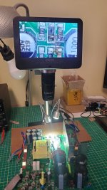
This board has an antenna in it and it is fully wireless picking up power / data from the main board.

The board rotates with the drive shaft and contains two strain gauges as torque sensors. The grey magnet is for the Hall effect sensor for measuring rotation.


That’s the board that sits over the sensor board and wireless picks up the data. That’s particular motor was F’d as it had been pressure washed so was flooded. Most of the time with these motors it’s an issue with bearings and if those go out one of. The cascade of effects is damage to these two. Parts since the tolerance are so tight.
I’ve been able to fix 90% of them, but if I can take care of these board repairs I can get that ratio up to 95%. Or at the very least it helps me out with salvaging parts to use for other motors. I do have a on of parts I can practice my skills on too.
Part of the challenge with using a bench top power supply with these motors is the battery management system. I can’t just apply power and try to trick the management system by applying power to those leads as well. If it doesn’t get the actual data from one of their brands batteries via the bus system it immediately goes into a safe mode and throws codes. The bus system transmits everything from the batteries power data, charge cycles, firmware version and battery SN. If I could crack that it would make things way easier. For example some of these motors while. Being physically identical are locked out in the firmware to only work with a specific battery.


")