To avoid these ads, REGISTER NOW!

Between 485 & 705 SQ/FT Mid-Century Moto Mecca Makeover

Workspaces between 485 and 705 squarefeet.

wout

Well-known member
Joined
Dec 26, 2013
Messages
786
Location
Belgium
Well done! Congrats with this very nice piece of machinery. Always hard to choose between free space and tools/machinery...
Had no help around to get my 'Jaspar' mill of the pallet so had to be inventious. I temporally fixated a steal beam to the ceiling with extra stands supporting it just where the mill had to come. Then pulled it up with a chain hoist.
 

Attachments

  • 2524C74E-7C78-4E57-91DF-A19EEF2FB67D.jpg
    2524C74E-7C78-4E57-91DF-A19EEF2FB67D.jpg
    112.3 KB · Views: 335
Last edited:
To avoid these ads, REGISTER NOW!

Vertigo Cycles

Well-known member
Joined
Jan 14, 2010
Messages
193
Location
Portland, OR
Glad to be of some assistance and more-so that my my abundance of caution was useful. I had no idea that we were going to be treated to that amazing pizza, so that was a pleasant surprise.
 

Growlertdi

Well-known member
Joined
May 17, 2016
Messages
410
Location
Millersport, Ohio
Gregor, you have created a monster. I have never cooked like this in my life.

This pizza was AMAZING!!!. Thank you for sharing.

We have 6 more pizzas worth of sauce in the freezer.
 

Attachments

  • Resized_20200104_184428.jpg
    Resized_20200104_184428.jpg
    94.1 KB · Views: 244
  • Resized_20200104_185213.jpg
    Resized_20200104_185213.jpg
    104.6 KB · Views: 215
  • 20200104_182919.jpg
    20200104_182919.jpg
    101 KB · Views: 201
OP
S

sakurama

Well-known member
Joined
Oct 10, 2010
Messages
1,458
Location
Portland - the cool one.
Congratulations on the successful move of the Bridgeport but where are the.... MF'n pancakes to celebrate the win?

Right here *******!

i-gNWmtJJ-X2.jpg


Gregor, you have created a monster. I have never cooked like this in my life.

This pizza was AMAZING!!!. Thank you for sharing.

We have 6 more pizzas worth of sauce in the freezer.

I am so glad you gave it a try and I have to say for your first time that turned out better than my example pizza. Sometimes starting the dough at night and then leaving it to the morning gives it a better rise. One thing you can always do to make dough fit your schedule is to put the container in the refrigerator. This has the effect of slowing the rise by about 80-90% and it really helps to develop the flavors. I'll often make the dough at night (right now I'm making a sourdough to leave overnight) and then in the morning I'll put it in the fridge to slow the rise down until later in the afternoon when it's convenient for me to bake it. Same can be done with pizza.

So that looks amazing and you got a really nice rise - you did good!


______________________________________________________________​


So we're going to take a turn back towards the bikes in this thread but for now we're going to stay on the Bridgeport. Much like picking up a used bike the first thing you want to do is clean it and see what you actually got.

i-2Jp8q8P-X2.jpg


When I was looking at this mill on the auction site I studied the photos for hours probably. I asked for extra photos and I asked for dates and history. It was a risk to buy a machine like this sight unseen but lots of details told me that it was a solid mill poorly presented. The first detail was there were no, zero, table touch downs. No one has ever drilled through their backing plate in the last 40 years and put a hold in the table. Amazing.

i-xzwrfCc-X2.jpg


The other was that I could see flaking on the ways through the grease and what looked like rust but I was hoping was just dried grease. Flaking marks are those scallops you see in the bottom there. That is the hand scraping done to make the way interface flawlessly and over time it a machine with a lot of use will wear those marks away. Those two things told me that the mill wasn't a production machine and wasn't used by lackeys. I was told it came out of a small prototyping shop and that also told me it had probably been cared for but then had sat for a long time. The one shot oiler still had oil in it. The DRO scales were very old so it probably hadn't been used in a long time and that meant low milage.

i-LspwjvM-X2.jpg


i-NwzKjfT-X2.jpg


i-vXcBsRW-X2.jpg


The mill I'd owned before was filthy when I bought it. Literally so dirty you couldn't tell what color it was. It took a solid two weeks to clean it but what I found was a mill perfectly preserved under a coat of hardened grease and oil. It looked so ugly I got it for $1500 and after 10 years of use I sold it for $4500.

I like dirty machines if I can see what's under it.

i-J5BxS8B-X2.jpg


For cleaning a dirty machine tool my favorite two things are WD40 and Purple Power degreaser. I spray the whole thing down one section at a time and let it sit to loosen the grease. The Purple works great on grease and the WD40 works great on light rust. The other thing is green scotchbrite pads and a lot of paper towels.

i-TsLW55m-X2.jpg


i-HXC9Czz-X2.jpg


Handles tend to rust but ways don't because they're always covered in oil - which is just how you want it. I'll pull the handles and either wire brush them with a fine wire wheel on the grinder...

i-mkCsVQ6-X2.jpg


...or, for anything round, I'll chuck it up in the lathe and run it on a medium speed with some scotchbrite.

i-cnLTpBD-X2.jpg


i-QdWLcJq-X2.jpg


i-JtJfJKL-X2.jpg


i-c9Mw8Lk-X2.jpg


i-DM8DVt8-X2.jpg


These sort of parts clean up really well this way.

i-MX2QvnD-X2.jpg


These just require a lot of elbow grease.

i-SF7ZS4g-X2.jpg


i-SXSxMGq-X2.jpg


Believe it or not this light cleaned up and I even cleaned the bulb that came with it - and it works. I mean, I just saved another $4 bucks at least.

i-qzjgGww-X2.jpg


The ways were stiff but I sprayed them down with WD40 and they're loosening up and now the power feed is working very well. Quite thrilled to have a nice Bridgeport power feed. It's as close to CNC as I'm getting.

Tomorrow I want to get the machine powered up and pull the DRO scales that are on it off. I'll clean them and sell them on ebay and use that money to fund a z-axis power feed. But to get the machine powered up I need a VFD or Variable Frequency Drive.

While I have two of these; for my lathe and cold saw, their instructions and installation is cryptic at best so my bed time reading tonight will be the manual for the Teco.

i-fkkKQdW-X2.jpg


I am not quite sure how to wire it so that I can still use the Bridgeport power switch. I'm pretty sure I have to wire the machines switch to the control wires but I honestly don't know if the Bridgeport reverses the motor via gears or electronics. Got any advice Lil Scorpion?

Also, a very big day on the shop layout. I sold one of my drill presses to my friend Scott for a great deal, yanked the tire machine out and put that up for sale and am staying true to my promise to keep three feet between machines.

Lara and I are pretty tired from moving machines and cleaning all day but I'm hoping to have the mill up and running by Monday/Tuesday and then buckle down on the bike.

Gregor
 

wout

Well-known member
Joined
Dec 26, 2013
Messages
786
Location
Belgium
Hello Gregor

Very nice work on the cleaning job! I clean my old Hazet wrenches the same way (oil and scoth bride). The mill looks 100 times better allready.

Why are you using the VFD? Because you don't have 3 phase power and/or to control the speed of the mill? Or some other reason?

Thanks!

Wout
 
OP
S

sakurama

Well-known member
Joined
Oct 10, 2010
Messages
1,458
Location
Portland - the cool one.
Hello Gregor

Very nice work on the cleaning job! I clean my old Hazet wrenches the same way (oil and scoth bride). The mill looks 100 times better allready.

Why are you using the VFD? Because you don't have 3 phase power and/or to control the speed of the mill? Or some other reason?

Thanks!

Wout

In the states residences almost never have three phase power but commercial buildings always do. Some people will run rotary phase converters to convert single phase to three phase but I never liked that option. On my lathe and cold saw I use the VFD for quick or fine speed control but on the mill I just want to covert the power.

I may look into some of the VFD programming options but mostly it’s just going to convert the power.

Gregor
 
Last edited:

wout

Well-known member
Joined
Dec 26, 2013
Messages
786
Location
Belgium
I the states residences almost never have three phase power but commercial buildings always do. Some people will run rotary phase converters to convert single phase to three phase but I never liked that option. On my lathe and cold saw I use the VFD for quick or fine speed control but on the mill I just want to covert the power.

I may look into some of the VFD programming options but mostly it’s just going to convert the power.

Gregor

Gregor

Thanks for the explanation. In Belgium you can ask for it in domestic buildings to (not cheap) and depends from where you live if you get 3x230V or 3x400V+N. When you get a new connection (new build or big renovation) you can ask for single phase higher Amp (standard) or a bit lower Amp but 3 phase for the same price. I was lucky my house already had a 3X230V connection when I bought it. Cause I have some machines that can't be connected to 3X230V, I bought a 6.6KVA 3x230V to 3x400+N transformator. So I have both currents in my garage/shop.

Wout
 

mannydantyla

Well-known member
Joined
Jan 24, 2019
Messages
160
Location
LFK
This will be somewhat off the topic of your Bridgeport but I just want to say that I too live in Portland and it's a great city. But housing here is a bit expensive as you probably know so congrats on finding a place that's affordable! Is it centrally located or nah? I'm in the South Portland neighborhood (west of the Ross Island bridge) and it's pretty dense and I feel incredibly fortunate just to have an 11x18 garage. But rent is well over $2k/month and because of that and several other reasons we're moving back to the midwest to buy a house at a reasonable price lol. But I will miss this city so much!

Cheers mate, maybe I'll see you at the 1 Moto Show... look for a blue Honda CL200 on display that one will be mine :)
 
Last edited:

Finallygotit

ALLIANCE MEMBER
Joined
Jul 6, 2013
Messages
4,083
Location
Tucson, AZ
Gregor, for the Bridgeport, the low speeds are accessed by moving the lever on the side of the head into what they call backgear and reversing the motor. I'm using a static three phase converter with no issues (and no rotary noise). Yes, you will not have full horsepower but with the kind of work I do, I won't need it.


:beer:
 

lilscorpion

Well-known member
Joined
Mar 15, 2010
Messages
3,600
Location
Colorado
I am not quite sure how to wire it so that I can still use the Bridgeport power switch. I'm pretty sure I have to wire the machines switch to the control wires but I honestly don't know if the Bridgeport reverses the motor via gears or electronics. Got any advice Lil Scorpion?


Gregor


Gregor - first, congrats on moving in!! Huge step, the rest is downhill. You’re gonna have fun.

Regarding the wiring - I’d have to look inside yours but mine didn’t have the 3 phase going through the switch, the switch just triggered a contactor (I think they’re called) that was installed in a little box on the side of the machine.

e7e02bddc1be5ca086a6e64978623d6e.jpg

That being said, I think none of that matters. If you turn on your VFD and connect the 3 phase output to a box, and plug your 3 phase plug into that box, it’ll probably all work just like it is and the switch will turn on/off the mill. The switch will not obviously control the VFD, you’d have to turn it on manually first.

There’s probably also a higher tech solution out there like maybe a multi stage contactor (I’m making it up) that would let a 110v switch first send power to the VFD and then trigger the main 220 3 phase source.

Matt
 

Attachments

  • e7e02bddc1be5ca086a6e64978623d6e.jpg
    e7e02bddc1be5ca086a6e64978623d6e.jpg
    43.7 KB · Views: 2
Last edited:

Prometheus

Well-known member
Joined
May 17, 2006
Messages
104
Gregor,

If you haven't checked it out yet, the guys at owwm.org will be able to help you with your vfd in their sleep. I wouldn't be surprised if there was already several threads describing how to wire up a 3 phase Bridgeport in the electrical sub forum. One quirk, I think you have to register to be able to read the electrical forum. Hope that helps.
 
OP
S

sakurama

Well-known member
Joined
Oct 10, 2010
Messages
1,458
Location
Portland - the cool one.
Gregor, for the Bridgeport, the low speeds are accessed by moving the lever on the side of the head into what they call backgear and reversing the motor. I'm using a static three phase converter with no issues (and no rotary noise). Yes, you will not have full horsepower but with the kind of work I do, I won't need it.


:beer:

Gregor - first, congrats on moving in!! Huge step, the rest is downhill. You’re gonna have fun.

Regarding the wiring - I’d have to look inside yours but mine didn’t have the 3 phase going through the switch, the switch just triggered a contactor (I think they’re called) that was installed in a little box on the side of the machine.

e7e02bddc1be5ca086a6e64978623d6e.jpg

That being said, I think none of that matters. If you turn on your VFD and connect the 3 phase output to a box, and plug your 3 phase plug into that box, it’ll probably all work just like it is and the switch will turn on/off the mill. The switch will not obviously control the VFD, you’d have to turn it on manually first.

There’s probably also a higher tech solution out there like maybe a multi stage contactor (I’m making it up) that would let a 110v switch first send power to the VFD and then trigger the main 220 3 phase source.

Matt


Call me sentimental but I love the old switches of big machines. My lathe is wired so I can turn it on with the apron switches and I'd like to do the same for the Bridgeport.

i-4zCdtqT-X2.jpg


I think that the only way to do that is to run power from the wall (230 single) to the VFD L1 & L3 (inputs) and then run the power out of the VFD to the motor T1, T2, T3 and then use the switch as a signal to the low voltage inputs of the VFD controls. But for high and low I'm not sure how that works.

I read that you don't want to send your power through the switch but I don't know why yet - that's how it works now. I know you can vary speeds via the VFD but you also loose torque doing that. I may want to add a speed pot down the road like my lathe has but right now I want to try the mill with as minimal wiring and stuff as I can and just use the stock switch...

Gregor
 

lilscorpion

Well-known member
Joined
Mar 15, 2010
Messages
3,600
Location
Colorado
Call me sentimental but I love the old switches of big machines. My lathe is wired so I can turn it on with the apron switches and I'd like to do the same for the Bridgeport.


I read that you don't want to send your power through the switch but I don't know why


Looks to me like the power runs through the switch. If your VFD is going to be set to 100% and never change, I can’t imagine why you couldn’t just run the 3 phase from the VFD into the switch and then use the switch to power the motor.
 

WhoWhatNow

Well-known member
Joined
Feb 22, 2011
Messages
1,889
Location
Collegeville, PA
You do not want anything between the VFD and the motor. You can put a switch before the VFD but not after it. That said, you can still use the original drum switch to control the direction of the motor. You can wire the switch in as a remote switch. I believe you use S1-S5 inputs. (https://www.tecowestinghouse.com/Manuals/L510_instruction_manual.pdf)


I’ll get some pictures of my setup shortly.

My setup is with an older version of your VFD but should be similar.

Power comes in from the wall up top.
a61d07f2e521def27d0e7d2bcc646783.jpg

Power goes directly to the motor (3 black wire in the back) out the bottom.
The other pair of wires are for the remote controls. These are low voltage for a SPDT switch to control direction and a 10K pot for speed.
d32149bb609c33fb3940b497caf600b0.jpg

And remote switch and pot:
eb10d877b030c538c21cd5c17beb9557.jpg
 

Attachments

  • d32149bb609c33fb3940b497caf600b0.jpg
    d32149bb609c33fb3940b497caf600b0.jpg
    213.7 KB · Views: 1
  • a61d07f2e521def27d0e7d2bcc646783.jpg
    a61d07f2e521def27d0e7d2bcc646783.jpg
    96.4 KB · Views: 0
  • eb10d877b030c538c21cd5c17beb9557.jpg
    eb10d877b030c538c21cd5c17beb9557.jpg
    230.5 KB · Views: 16
Last edited:
OP
S

sakurama

Well-known member
Joined
Oct 10, 2010
Messages
1,458
Location
Portland - the cool one.
You do not want anything between the VFD and the motor. You can put a switch before the VFD but not after it. That said, you can still use the original drum switch to control the direction of the motor. You can wire the switch in as a remote switch. I believe you use S1-S5 inputs. (https://www.tecowestinghouse.com/Manuals/L510_instruction_manual.pdf)

Thanks.

Yes, I'm gathering that VFD's don't like their power interrupted hence why you should not have any switches between the motor and VFD.

I'm was confused about the high and low speed switch but from what I've read "high" and "low" are actually forward and reverse? It's just that when you run backwards (Low) you engage the back gear and then that reverses the gears so that it's now running forward but geared down.

It's been more than 10 years since I've run a Bridgeport and I can only vaguely remember how they work but that sounds familiar. I've found the manual for it and will also now read that as well but lacking a switch I want to figure out how to use the drum switch to control forward/reverse - ie which contacts. From Practical Machinist:

Remove the motor wiring from the drum switch and remove the power wiring from the drum switch.
Wire the motor directly to the VFD termianls T1(U), T2(V), T3(W)
Use the top row of Drum Switch contacts or the row closest to the switch knob. This should have no jumpers on it. If there are jumpers then remove them. The bottom two rows will not matter.
Wire from the 24V power terminal, of the VFD control termianl strip, to the center contact. Wire from the FORWARD terminal of the VFD terminal strip to the drum switch termianl on the Forward position.
Wire from the REVERSE terminal of the VFD control strip to the drum switch terminal on the Reverse position.

Mount a disconnect for the incoming power and wire the power to the VFD terminals L1(R), L2(S) and L3(T) if you have 3 phase power. If single phase you will have to try L1 and L2.


So I'm going to try to figure this out...

G
 
Last edited:

Finallygotit

ALLIANCE MEMBER
Joined
Jul 6, 2013
Messages
4,083
Location
Tucson, AZ
I'm was confused about the high and low speed switch but from what I've read "high" and "low" are actually forward and reverse? It's just that when you run backwards (Low) you engage the back gear and then that reverses the gears so that it's now running forward but geared down.


You are correct. The motor spins at the same speed, just forwards or backwards.


:beer:
 

elvee

Well-known member
Joined
Nov 1, 2006
Messages
309
Location
Atlanta, GA
I read that you don't want to send your power through the switch but I don't know why yet - that's how it works now. I know you can vary speeds via the VFD but you also loose torque doing that. I may want to add a speed pot down the road like my lathe has but right now I want to try the mill with as minimal wiring and stuff as I can and just use the stock switch...

Gregor

I can't speak to the wiring concerns, but I think I can give some light on the question of the big switch. There have been updates to the electrical codes around the world for three phase motor operation over the last 30 years. The biggest addition to the codes have been requirements that mains power not be flowing through the control switches. In my day job world, this means that electric chain hoists can be three phase, but that three power can't flow through the control pendant. There are two options - direct control and low voltage control. Direct control handles direction via a reversing contactor located outside the motor housing, feeding mains power to the motor winding. Low voltage control has mains running straight to the motor housing, with a reversing contactor inside the motor housing and a control circuit exiting and returning to the housing. The "low voltage" can be anything from 12V to 110V, but at a very low amperage. The whole point of all this is to not have full load amperage in the switch that the operator is touching.

I hope I have provided some small bit of minimally useful information about three phase motor systems for you all.
 

lilscorpion

Well-known member
Joined
Mar 15, 2010
Messages
3,600
Location
Colorado
I can't speak to the wiring concerns, but I think I can give some light on the question of the big switch. There have been updates to the electrical codes around the world for three phase motor operation over the last 30 years. The biggest addition to the codes have been requirements that mains power not be flowing through the control switches. In my day job world, this means that electric chain hoists can be three phase, but that three power can't flow through the control pendant. There are two options - direct control and low voltage control. Direct control handles direction via a reversing contactor located outside the motor housing, feeding mains power to the motor winding. Low voltage control has mains running straight to the motor housing, with a reversing contactor inside the motor housing and a control circuit exiting and returning to the housing. The "low voltage" can be anything from 12V to 110V, but at a very low amperage. The whole point of all this is to not have full load amperage in the switch that the operator is touching.


I hope I have provided some small bit of minimally useful information about three phase motor systems for you all.


Good info, that explains why mine was wired the way it was.


Sent from my iPad using Tapatalk Pro
 
OP
S

sakurama

Well-known member
Joined
Oct 10, 2010
Messages
1,458
Location
Portland - the cool one.
I would love to really understand electricity in a meaningful way. I get better with time but still.

i-Cw2VLGQ-X2.jpg


So yes, you guys are correct - you can't have the high current flow through the switch because VFD's don't want their load interrupted. I photographed the switch and then pulled all the wires out of it so I could bypass it.

i-vXXwp27-X2.jpg


I struggled for a while about where to put the VFD and decided that since it has a speed control (or rather a knob that can be programmed to be a speed control) on the front panel it would make sense to place it close to mission control which is the DRO. I luckily had some scrap aluminum and welded up an angled bracket that would place the VFD directly under the DRO display to keep things compact.

I had two scares after plugging it all in. The first one when I turned it on and it barely moved. For some reason the VFD was defaulted to 5hz instead of 60 so once I changed that the motor spun. It's not as quiet as I'd like and it may be that I'll need to replace the belt which might have a flat spot from sitting so long.

Then next was after placing a drill chuck in the spindle and turning it on and seeing it wobble. I had the light headed dizzy feeling you get when something has gone horribly, horribly wrong and you'll never be able to fix it. Please tell me the spindle isn't bent - that's impossible. Oh, no...

Then I tightened it down and it was fine.

i-GCTZ85L-X2.jpg


She's a runner. I need to read up on it and become familiar with it again - everything is different from my old mill. Including how damn high the head is to tighten the spindle. Plus I'll need to make a new wrench for the spindle and I've been wanting to do that for a long time.

Tomorrow I'm going to work on pulling the old scales, cleaning it, figuring out how to wire the drum switch to work as the power switch/reverse switch and mounting the new DRO scales. Luckily the mill is now operational which is very helpful for machining brackets to mount the DRO.

The best part of the whole night was that I actually completed a small project in the new space. It feels so completely different. The layout is better, there is much more space to walk and move and it feels fantastic to work in. If I can only figure out where things are it will be amazing.

Gregor
 
To avoid these ads, REGISTER NOW!

esvee

Well-known member
Joined
Dec 28, 2014
Messages
171
Location
Portland, OR
I'm late to the update, but (Rob here), I can confirm the Bridgeport was heavy, Gregor's pizza is delicious and linoleum tile is in fact a terrible garage floor choice.

I left the moving party feeling inspired to make more pizza and straighten out my own shop. A good day with good people.
 
Last edited:

jdp993

Member
Joined
Aug 30, 2006
Messages
21
Congratulations on the shop clean up and layout changes. I am looking forward to the photo essay of the new configuration.

I saw the short video you posted on Insta of the switch wired in to the VFD. The mill sounds noisy, more than what I would expect. It would be worth digging into the source of the noise before running the mill too much. It doesn't sound like belt noise more like bearings but hard to tell from the short clip. It's much easier to change the bearings, spindle or motor, before they actually fail. I've learned this the hard way.
 

bdbecker

ALLIANCE MEMBER
Joined
Nov 18, 2015
Messages
5,564
Location
Iowa
I would love to really understand electricity in a meaningful way...

I thought of two somewhat snarky comments when I read this. I couldn't decide which one would be better, so I'll just post both...

"Says the guy who recently posted a fantastic write up on servicing mechanical watches."

and...

"Finally... something that I probably know more about than Gregor."

Looking forward to the motorcycle build photos. I think I'm finally going to give in and setup an IG account so I can follow along in real time.
 

lilscorpion

Well-known member
Joined
Mar 15, 2010
Messages
3,600
Location
Colorado
The mill sounds noisy, more than what I would expect.


Agreed though kinda hard to tell. Make sure it’s been serviced since it’s set for a while. Oil the service locations frequently enough is important including spindle daily.
 

Terranova

Well-known member
Joined
May 12, 2008
Messages
854
Location
Grove City, OH
It’s great to switch things up and feel that it’s an improvement. And what a great feeling to find a piece at a reasonable price and know or find out that it’s solid, unmolested and just dirty. Love it.
 
OP
S

sakurama

Well-known member
Joined
Oct 10, 2010
Messages
1,458
Location
Portland - the cool one.
I saw the short video you posted on Insta of the switch wired in to the VFD. The mill sounds noisy, more than what I would expect. It would be worth digging into the source of the noise before running the mill too much. It doesn't sound like belt noise more like bearings but hard to tell from the short clip. It's much easier to change the bearings, spindle or motor, before they actually fail. I've learned this the hard way.

Agreed though kinda hard to tell. Make sure it’s been serviced since it’s set for a while. Oil the service locations frequently enough is important including spindle daily.

I am worried about that although it's much quieter now that it's been run a little. I put the vise on last night and went to tram the head and realized I couldn't lower the spindle. This could be me being an idiot and not having the controls set right or it could be stuck or maybe worse.

The mill didn't come with a quill lever or a fine feed wheel. The fine feed is supposed to be in the middle of it's in and out travel but doesn't seem to move. I've ordered them but they're not here yet so I'm going to just keep going today with pulling the scales.

Two steps forward, one step back.

I thought of two somewhat snarky comments when I read this. I couldn't decide which one would be better, so I'll just post both...

"Says the guy who recently posted a fantastic write up on servicing mechanical watches."

and...

"Finally... something that I probably know more about than Gregor."

Looking forward to the motorcycle build photos. I think I'm finally going to give in and setup an IG account so I can follow along in real time.

Oh I'm sure that's a longer list than you imagine. If this thread was about all the failures I've had it would be much longer.

Gregor
 

Vertigo Cycles

Well-known member
Joined
Jan 14, 2010
Messages
193
Location
Portland, OR
I am worried about that although it's much quieter now that it's been run a little. I put the vise on last night and went to tram the head and realized I couldn't lower the spindle. This could be me being an idiot and not having the controls set right or it could be stuck or maybe worse.

The mill didn't come with a quill lever or a fine feed wheel. The fine feed is supposed to be in the middle of it's in and out travel but doesn't seem to move. I've ordered them but they're not here yet so I'm going to just keep going today with pulling the scales.

Two steps forward, one step back.

Gregor

probably stupid questions, but worth it to cover all the bases...is the quill lock on? Is the quill stop adjusted in a way that locks it?
 
OP
S

sakurama

Well-known member
Joined
Oct 10, 2010
Messages
1,458
Location
Portland - the cool one.
probably stupid questions, but worth it to cover all the bases...is the quill lock on? Is the quill stop adjusted in a way that locks it?

So I was pretty worried about the quill but at the same time it's a very simple mechanism so I kept thinking it was just stuck with dried grease. I sprayed the quill as much as I could with some WD40 and moved on to let that soak.

i-hwM8RmK-X2.jpg


At this point the ways were also pretty stiff so I wanted to really clean them good so I sprayed them down with degreaser and let soak a few minutes.

i-JMtrZdx-X2.jpg


Scrub with the green Scotchbrite and then wipe up with dry paper towels.

i-jQLKBCx-X2.jpg


I did the same with the ways of the X, Y and Z axis, cleaning with WD40 and wiping down and then giving them a light coating of way (to go!) oil. A friend wrote that on my bottle of oil and I've kept it. I always fee more accomplished.

i-j4hbjcF-X2.jpg


Despite some teething issues (non functioning quill!) I still feel like I got a great machine. I've never seen ways so clean and unworn and with all of the scraping everywhere. It almost seems like it was rescraped but the paint is all clean and original as well so I really think I got a very low milage mill.

i-PPLT28L-X2.jpg


I found and printed out the sections of the manual that went over the head functions and I was doing it all right but still the quill wouldn't budge. I finally called H&W Machine and the receptionist kept me on hold until she finally got a tech free. He was very patient and friendly and we double checked all the controls and then started taking it apart. He just stayed on speakerphone as I disassembled the quill feed mechanism.

i-MtxsfVp-X2.jpg


i-KRwbFx9-X2.jpg


After the whole thing was completely apart he said he was stumped. I mentioned that my feeling was that it was dried grease as the ways had been very tight and hard to move so we agreed that I should spray a bit of WD40 in the back of the spindle and give the drawbar a few taps.

And it broke free! It was pretty stiff at first but then it got looser and looser as the I worked the spindle up and down. You have no idea how relieved I was.

i-Nc8Qsvm-X2.jpg


Lara and I spent the remainder of the day cleaning the mill and the shop and I kept finding things that I could sell on ebay. I feel so good with all the space that I just want to get rid of more and more.

i-26tn89b-X2.jpg


Every time I lift this vise I think I must be some kind of wimp but it seriously felt like 100lbs. I asked Lara to guess and she said 50lbs which is what it seems like it should weight. But it actually does weigh 96lbs and I guess I'm not as wimpy as I first thought. Thankfully.

i-pFnhkjJ-X2.jpg


I got the vise squared on the mill by checking with a dial indicator and sweeping the back jaw...

i-kKg7KTk-X2.jpg


Then set the tram of the mill (the tilt of the head) with my special tramming tool. At this point I could probably start to make some chips so the next step is to fit the DRO scales to the mill. It would be really helpful to mill the parts for the DRO with the DRO but unfortunately I'll have to go old school there. I will say that all the controls have started to become very smooth and silky. The table doesn't coast but it's not hard to move which feels about right.

I'll go visit Metal Supermarkets tomorrow and pick up some aluminum stock that I can use to mill brackets to mount the DRO and then, finally, the mill should be pretty much done for the time being.

And then it's onto the project bike. I have only about two weeks to make this happen - it's like one of those chopper build shows...

Gregor
 

Brian R

Well-known member
Joined
Dec 1, 2009
Messages
591
Location
Chestertown, MD
"And then it's onto the project bike. I have only about two weeks to make this happen - it's like one of those chopper build shows... "


Except they guy doing it has mad skills and we know the drama is not made up and the final bike will be the real McCoy.


Great job on documenting this and I'm glad your process fixed the quill.
 

zmotorsports

ALLIANCE MEMBER
Joined
Oct 20, 2009
Messages
21,405
Location
Northern Utah
Nice score on the mill Gregor. Those ways look like new.:thumbup:

I'm sorry if I missed this but did you mention the table size? Looks like maybe a 49" wide?

As for your noise, our BP clone at work is pretty quiet but it's a step pulley style mill but my buddies older BP as well as my Taiwanese BP clone are the variable speed head and they both have some belt train noise upon first starting them up after sitting for a few days. Both quiet right down within a minute or two so maybe that's just a normal issue/noise on the variable speed heads. Mine has done it from day one and I bought it new so wear isn't the issue. My buddies is an older BP mill but very little use when he acquired it. Either way I haven't bothered much with it because it quiets right down and doesn't affect anything as far as surface finish, etc.

Also, you mentioned about the weight of your vise, I took the rotating base off of mine and just use the Kurt vise (or my Glacern) on the table without the base which is much easier to move around for various setups. I have a base but very rarely use it.
 
OP
S

sakurama

Well-known member
Joined
Oct 10, 2010
Messages
1,458
Location
Portland - the cool one.
Except they guy doing it has mad skills and we know the drama is not made up and the final bike will be the real McCoy.

Yeah, I am scaling back that build little by little as I run out of time but it's nice to know you have faith.

I feel like I have a lot of unfinished projects and so finishing the mill is important lest I start using it and it never gets set up correctly and becomes another unfinished project. Also, like most other things, the process of cleaning it is also a way to evaluate the whole thing plus having the DRO will really cut down on time when I need to make parts.

My hubs are going to be done today and then the wheels can be built which really gets things rolling. So to speak.

Nice score on the mill Gregor. Those ways look like new.:thumbup:

I'm sorry if I missed this but did you mention the table size? Looks like maybe a 49" wide?

Both quiet right down within a minute or two so maybe that's just a normal issue/noise on the variable speed heads. Either way I haven't bothered much with it because it quiets right down and doesn't affect anything as far as surface finish, etc.

Also, you mentioned about the weight of your vise, I took the rotating base off of mine and just use the Kurt vise (or my Glacern) on the table without the base which is much easier to move around for various setups. I have a base but very rarely use it.

When I asked the tech about the noise he said that there's two bushings on the back pulley and one is blue and the other is black and the blacks don't last as long. I may replace the belt and see but as the machine runs more it gets quieter. And you're right on the table - 48" which is really much longer than I wanted in a small shop but I figure I could have both the vise and the rotary table set up at the same time. Also, good point on the swivel base. I've never cared for them so I may get rid of it. My last vise indexed to the table which I loved so I may do that with this one.

Gregor
 

polexican23

Banned
Joined
Jun 11, 2013
Messages
2,168
Location
burbs-Illinois
"things I could sell...." but will you?

how many holes do you have in that snazzy vest? I wore that in the garage, it would get snagged and rip in about .983 of a second
 

shirk

Well-known member
Joined
Sep 2, 2011
Messages
90
Location
North Vancouver, BC
And then it's onto the project bike. I have only about two weeks to make this happen - it's like one of those chopper build shows...

Gregor

Can we set up a live web feed of Gregor's garage for the next two week? Just a single camera up in the corner showing the whole shop. Like one of those eagle nest cams waiting for the egg to hatch?
 

lilscorpion

Well-known member
Joined
Mar 15, 2010
Messages
3,600
Location
Colorado
And you're right on the table - 48" which is really much longer than I wanted in a small shop but I figure I could have both the vise and the rotary table set up at the same time. Also, good point on the swivel base. I've never cared for them so I may get rid of it. My last vise indexed to the table which I loved so I may do that with this one.


Strange thing about table size I’ve learned is that I typically use a single vise’s worth of space but when I do need more, I’m frequently trying to machine a part that’s longer than the table. I’d sacrifice shop space to have my 42” table be 6” longer.

The machine feels big now but that feeling softens over time as you make it become more organically part of your workflow and processes.
 
OP
S

sakurama

Well-known member
Joined
Oct 10, 2010
Messages
1,458
Location
Portland - the cool one.
"things I could sell...." but will you?

how many holes do you have in that snazzy vest? I wore that in the garage, it would get snagged and rip in about .983 of a second

You would think I wouldn't but I'm seriously cutting back. I sold that BMW RS I bought with the good intentions of fixing and flipping. I just sold the old front end to the GS BMW and I put the rest of those parts on ebay. So believe it or not I'm getting rid of stuff. Crazy I know.

Also, about three holes - it's old. Before clothes go to Goodwill or the trash they become shop clothes - also, Patagonia has a lifetime repair warranty! I should wear my overalls but I don't.

Can we set up a live web feed of Gregor's garage for the next two week? Just a single camera up in the corner showing the whole shop. Like one of those eagle nest cams waiting for the egg to hatch?

The best I can offer you is Instagram stories. I'm surprised at how much people like those and they're very easy for me to do. It's about the only social I can handle besides this.

i-LvDZsHH-X2.jpg


So yesterday I dove headlong into the DRO mounting. I mentioned to my friend Scott that I should probably just put off getting the mill set up until after the show and he was pretty categorical, "No way dude - knock that out - nothing is more important than making the mill right" and he was and always will be right.

i-JwpKqf4-X2.jpg


Building the DRO mounts with the mill is very much like building the machine with the machine - it's meta. I started with the X (sideways travel) because it seemed the simplest. I bought a bunch of stock from Metal Supermarkets and some of it was angle to cover the scale and give it some protection. This scale is flush with the top so it's the closest to damage. I turned some spacers to push the angle out slightly to make it all neat.

i-qrNftJQ-X2.jpg


It was interesting to actually use the dials on the mill to measure things. I just never do that and realized that it's strange because you don't look at the work but rather at the dial so you can't see yourself coming up on the mark. But this bracket has a very slight relief cut to allow for table travel. Here I'm using the red head holders to hold the head in position and then scribe a line for the cut on the bracket. I'm trying to make all the brackets as simple as possible.

i-n6KG8FM-X2.jpg


The scale needs to be straight to avoid errors so I used this digital one because it's all that would fit up into the scale. I would lock one side and just tap the other slightly until I could travel most of the length with no movement.

i-CNK6b8Z-X2.jpg


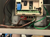
I want to avoid drilling into the mill as much as possible so my mounting solutions looked for ways to use any existing holes. For the Y-axis (in and out of the table) there were two milled flats from the factory so I used those and to mount a bar and then mounted the scale to that. This kept it straight and square. Here I'm using a tap in the drill to clean out existing holes.

i-bdFNVht-X2.jpg


Can I just tell you how much fun it is to actually use this mill? It's a fricking BEAST! Sure my old mill was smaller and I always knew that I had to baby it on my cuts but having the power to just plow through metal is pretty intoxicating. I have no doubt that I will probably break some tooling as I learn to push the machine but damn it's fun to just take a cut and not worry.

i-Ths42Bq-X2.jpg


Using the factory holes was baller - not even a thou out over the whole travel.

i-LdN87Dd-X2.jpg


A part of me wanted to pull the fly cutter down and just make all the brackets look pretty but more of me just wanted to make it work and move on. I seriously spent about 8-10 hours on this and it was 11pm before I finished the X and Y.

i-6TcnJZV-X2.jpg


I thought about quitting but realized I need to start on the bike and I had to finish. I was a little hazy and was afraid of making a mistake so I took a short break to look up images of Z-axis mounting solutions because the way I started to do it would have put the scales opening right in line with the chip path. I knew that was bad but I couldn't think clearly how to fix it. After looking at a few photos I realized I needed to mount it backwards and then grab the reader head from underneath.

I kept thinking back to my first mill and how I would make mistakes - grab the wrong tap or drill, make something not square or just generally screw things up. I kept waiting to do that here as I would pick up a drill bit and not check it and start drilling but I guess I have a lot more skill now because I didn't make a single mistake all night.

i-KKqx734-X2.jpg


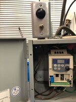
The bench is a hot mess of tools and the floor was covered in chips when I went to bed at 2am but the mill is done and dusted with readouts on all three axis. It is such a beast of a machine. Climb cutting with a 3/4" end mill was like nothing. Sure it's aluminum but this mill is night and day compared to my old one. I honestly could not be happier right now. Just couldn't.

i-H8wJrrR-X2.jpg


Meanwhile Lara is just knocking things out. While I was working on the mill she was pulling apart the compressor in preparation for the new single phase motor.

i-Zp39MFt-X2.jpg


I finally got to use that stupid Snap-On gear puller I've owned for like 15 years and never used.

i-L9xdbCm-X2.jpg


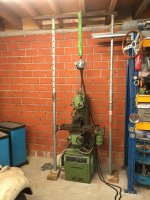
So this is the layout for the moment. I struggle with the need for more counter/table space and the desire to limit the spread of junk that takes over. I think getting rid of the garage door will give me a new wall and then I can make a few more cabinets to store things which might allow me to get rid of one of the rollers. That would give me some very needed floor space.

Also, I've been designing a new bench for about 5 years and after the bike I'm going to build it. It should make things much better as it will have storage under it.

The best bench I ever saw was by Nastyzen here on GJ but his thread is missing all the images. A second version that was good was this one: https://www.garagejournal.com/forum/showthread.php?t=193399&showall=1

Alright. I feel like a truck ran over me but it's nothing Advil and coffee can't cure. I'm going to clean up last nights mess and start getting after it.

Gregor
 
OP
S

sakurama

Well-known member
Joined
Oct 10, 2010
Messages
1,458
Location
Portland - the cool one.
Well, if you're ever curious what I'm not good at electricity would be pretty far up on that list. I spent most of the day trying to install the new single phase motor and get it wired in with it's magnetic starter but despite many YouTube videos, a dozen wiring diagrams and even a FaceTime call with a helpful person on IG...

i-49bkLCM-X2.jpg


I am not getting power to the motor.

So I gave up.

i-xJWgQ8h-X2.jpg


And gave Lara a lesson on the lathe. She made a great spacer.

i-mRLjPWQ-X2.jpg


So tomorrow I'll get you up to speed on the bike. I'm too tired now...

Gregor
 

dhubbard422

Well-known member
Joined
Jan 16, 2011
Messages
472
Location
Texas Hill Country
Congrats on getting the mill in place and set up to make chips fly! Your garage is looking like a very interesting shop space. I look forward to watching what you do in there next.
 

TedU

Member
Joined
Jan 1, 2016
Messages
23
Location
Dunwoody GA
Well, if you're ever curious what I'm not good at electricity would be pretty far up on that list. I spent most of the day trying to install the new single phase motor and get it wired in with it's magnetic starter but despite many YouTube videos, a dozen wiring diagrams and even a FaceTime call with a helpful person on IG...

i-49bkLCM-X2.jpg


I am not getting power to the motor.

I have the same compressor and also installed a rebuilt motor and new magnetic starter.
It's been a few years but I remember some of the wiring didn't make sense to me either (so I called my Electrical Engineer friend).
Happy to take pictures / share information as well if you don't get it figured out.
 

TurnipTruck

Well-known member
Joined
Aug 28, 2005
Messages
1,567
Location
Southcentral Alaska
Gregor: it looks like your incoming power should land on the top of the contactor , then out the bottom of the contactor to the motor. Main power does not go through the pressure switch with a contactor. I can’t tell where the red wires come from, but the contactor coil is activated by just one of the incoming leads hooked through the pressure switch. This activation circuit also runs through the lower contactor block if overload “heaters” are used. I see a red button that may be an overload reset, so you may need the correct heaters for the load. I can’t tell if they are missing or not.
 
To avoid these ads, REGISTER NOW!
Top Bottom