To avoid these ads, REGISTER NOW!

Mill head tramming, alignment

mikegt4

Well-known member
Joined
Sep 12, 2005
Messages
3,277
Location
sw ohio
This is one of the best videos that I have seen on tramming the head. Excellent explanation of the geometry particularly in the "nood" direction. The whole video is full of information and tips, if your impatient start about 3:45 for the tutorial.

For the video on building his Spindle Square:

Even a video on building a fancy wood case to store it in:

He has a huge play list of videos on all sorts of metal working subjects.
 
To avoid these ads, REGISTER NOW!

Monza Harry

Well-known member
Joined
Dec 29, 2018
Messages
1,433
Location
Windsor ON
Another thing to think of, is part/vice placement. I believe I have mentioned this before, do not place the work/vice/angle plate, in the center of the table always offset [and alternate from time to time] as the constant motion in that 6" of common work area will cause uneven wear on your machine, I have used machines worn so badly [unevenly] that the table ends could be moved a quarter of an inch at the end when centered but you couldn't even crank it to the end of travel. I just use a "Dial test Indicator" for squaring the head, the tool shown in that video above does only one job and while the DTI is much more expensive it is multiple times more versatile, it can be used for the head , vise, part pick up, on the grinder and lathe , on the surface plate with a surface gauge or height gauge for many many uses, money better spent. Fowler makes an "Interapid" clone for low cost. I make my living with my tools, more so in the past than now but I doubt many new apprentices would buy the Interapids I have. [PWC I realize you are going that route as well as part of your trade, but look them over before you spend or just consider it a secondary tool until you are done hemorrhaging start up money in this avenue you have started down ] Harry
This is the "Clone": https://www.fowlerprecision.com/Pro...tor-and-Accessory-Combo-Kit-52-562-100-0.html
One of these will be very handy: https://www.fowlerprecision.com/Pro...-All-Test-Indicator-Accessory-52-566-853.html
The first one I bought is a 312B2 and then a 312B-3
I would recomend the 312B-1 now. https://www.mcmaster.com/interapid-indicators/
 

RoninB4

Well-known member
Joined
Jul 22, 2020
Messages
3,619
Location
Under My House
I would agree with the above comment about the "spindle square" type being good for only one or two purposes. Yes tramming in the "nod" takes a bit longer but only a couple of minutes. Once I have side to side approximately equal I use that reading for the nod. Final reading/setting/adjusting comes next while the locking bolts are gradually tightened. It's a process, like many other things, of coarse to fine adjustment and should only takes a matter of minutes from start to finish. The "spindle square" type may reduce total time a minute or three but the expense seems like money better spent elsewhere, like on a standard dial test indicator (DTI) that is used on so many other applications. The difficulty mentioned in the videos of adjusting the nod seems rather exaggerated to me and nowhere near as time consuming as is made out to be.

If you're a hobby shop then use what you wish to but you're still going to need a DTI at some point for the lathe/surface plate/height gauge/hole location/etc.

If you're in the metal working trades like a machinist/toolmaker I'd suggest NOT making the "spindle square" type a first purchase over a standard DTI. They are often regarded as a gimmick for newbies or another piece for the toolmaker that already has everything. I could count on one hand the number of times I've seen them used in machine shops by experienced machinists. This is just my opinion, I'm not the last word on anything.
 
Last edited:
OP
P

PWC Repair

Well-known member
Joined
Dec 27, 2012
Messages
3,191
Location
Arkansas
Just got in a 4" round 'India' stone, AND a 6x2! I had them both in the cart and my wife misunderstood me and ordered both. I have been busy putting a 155hp 1200cc triple Waverunner engine together but going to try and run over that surface plate and the mill table today. Then check the tram again afterwards.
To be clear, I do have a regular DTI that I used on a bent piece of aluminum rod to set tram.....the second time.
 
OP
P

PWC Repair

Well-known member
Joined
Dec 27, 2012
Messages
3,191
Location
Arkansas
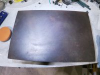
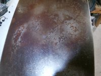
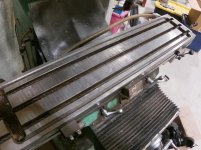
Allright, before and after.......2 hours of stoning this plate! It's a definate improvement but it's got a ways to go yet.
 

Attachments

  • GOPR0053.jpg
    GOPR0053.jpg
    125.3 KB · Views: 22
  • GOPR0055.jpg
    GOPR0055.jpg
    146.8 KB · Views: 21
  • GOPR0056.jpg
    GOPR0056.jpg
    147.2 KB · Views: 21
  • GOPR0057.jpg
    GOPR0057.jpg
    131.2 KB · Views: 21
OP
P

PWC Repair

Well-known member
Joined
Dec 27, 2012
Messages
3,191
Location
Arkansas
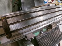
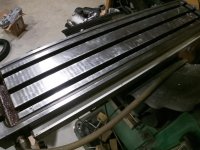
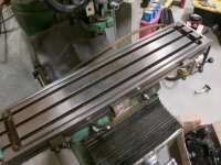
And here is before and after on the mill table. This one only took about 15 minutes! Then these lines or ripples showed up. I'm hoping this is a good thing,...maybe never been damaged and cut?? Factory machining marks perhaps? You guys let me know.
 

Attachments

  • GOPR0062.jpg
    GOPR0062.jpg
    148.9 KB · Views: 38
  • GOPR0061.jpg
    GOPR0061.jpg
    146.2 KB · Views: 40
  • GOPR0059.jpg
    GOPR0059.jpg
    150.8 KB · Views: 37
  • GOPR0058.jpg
    GOPR0058.jpg
    153.7 KB · Views: 39
OP
P

PWC Repair

Well-known member
Joined
Dec 27, 2012
Messages
3,191
Location
Arkansas
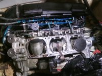
And just so you guys know what's taking me so long....a pic of the 155hp Yamaha triple I've been working on. It lost an oil line to the center cylinder and pooched a piston. Sent the cylinder out for replating, got one new piston, 3 sets of rings, quick hone on the other 2, rebuilt and modded carbs, and started reassembling.
 

Attachments

  • GOPR0064.jpg
    GOPR0064.jpg
    154.4 KB · Views: 17

Robert Haas

Well-known member
Joined
Sep 30, 2010
Messages
1,749
To the OP's issues with tramming. I have used a cylindrical square for years to quickly check tram and it is faster then any other technique I have needed.

"great you tube video of what a cylindrical square is. click for video"


mowkep

Well-known member
Joined
May 7, 2017
Messages
471
Location
Stow, Ohio
Very interesting. One of my machines is a bed mill with a bridgeport type head. It gets knocked out of alignment every so often. Like others I use a co-ax indicator to dial it in. Years ago, I remember having the cylinder squares to set up our horizontal machining centers after we moved to a new building.
 
OP
P

PWC Repair

Well-known member
Joined
Dec 27, 2012
Messages
3,191
Location
Arkansas
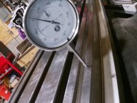
I had stated earlier I checked the tram with my dial indicator and it was within .005 in a 10" sweep. Well, it's actually 12".....6" all around the quill. Just checked it again, moved the table and knee around, then stopped in a random spot and rechecked. All still good! Pics aren't the greatest but you can see the needle stays between .0015 and .002"

Sidenote.....auto quill feed is operational. I just wasn't dropping the quill off the top stop first and that must be done to engage the feed
 

Attachments

  • GOPR0071.jpg
    GOPR0071.jpg
    151.7 KB · Views: 12
  • GOPR0070.jpg
    GOPR0070.jpg
    149.6 KB · Views: 15
  • GOPR0069.jpg
    GOPR0069.jpg
    132.6 KB · Views: 17
  • GOPR0068.jpg
    GOPR0068.jpg
    120.3 KB · Views: 15
  • GOPR0067.jpg
    GOPR0067.jpg
    120.3 KB · Views: 17
Last edited:
To avoid these ads, REGISTER NOW!
OP
P

PWC Repair

Well-known member
Joined
Dec 27, 2012
Messages
3,191
Location
Arkansas
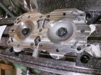
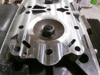
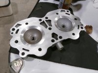
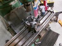
I hit the 'one shot' oiling system and ran the table around some......chattering noise went away. I read a bit about an end mill and the sharp corners leaving tooling marks. I chamfered the corners of the 4 flutes ever so slightly. Then I clamped down that same head, turned it up to 1100rpm, and had another go. It made a very smooth surface this go around. Then I rubbed it around a bit on some 220 grit on that surface plate. Turned out very nice. Would seal up just fine with a new gasket. I'm learning fellas!
 

Attachments

  • GOPR0083.jpg
    GOPR0083.jpg
    158.2 KB · Views: 29
  • GOPR0082.jpg
    GOPR0082.jpg
    136.7 KB · Views: 28
  • GOPR0084.jpg
    GOPR0084.jpg
    115.5 KB · Views: 30

RoninB4

Well-known member
Joined
Jul 22, 2020
Messages
3,619
Location
Under My House
This is just my opinion but the lines the OP mentioned in the photo appear to be a machine generated pattern due to the even spacing all along the table. If so, this would most likely be from a horizontal milling cutter used when the table was cut from the rough casting. The horizontal milling cutter was out of round ever so slightly when it was sharpened, the machine arbor may have had an out-of-round condition, or an excessive feed rate may have created a cyclic rise/fall with the advance along the table being milled. This is not uncommon to find on older machine tables. It showed up because stoning hit the high points and didn't touch the valleys. Even a ground surface will exhibit this if a fine enough abrasive is used, using the technique the OP did with the 220 grit on the surface plate. The "ripples" should be of no concern, I wouldn't even try to remove them. Why risk affecting the table flatness for something that's really just cosmetic.

To the OP- Congratulations, hope this is working out for you. Try to get a granite surface plate that's in good condition when the budget allows, it will be your reference surface for all other things in the shop. The cast iron one is nice but you still don't know how flat it really is and you'll want at least ONE reference surface you can count on for all other things. Good luck, ganbatte.
 
OP
P

PWC Repair

Well-known member
Joined
Dec 27, 2012
Messages
3,191
Location
Arkansas
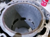
I had a REALLY beat up cylinder that I thought I'd try to bore. It was basically a core. Well....after the first pass almost all the damage cleaned out! So, I did some measuring and made another pass. I had to flip the cylinder each time and recenter it using the centering indicator off the previous cut. Because the quill is larger than the bore size. It worked out just fine, added about 15minutes each time. Then after the bore, I honed it to a finished size of 1mm over leaving .006" clearance. It's now a useable cylinder again.:thumbup: You can see one little dent to the right of the exhaust port, and there is another 1/4 x 3/8 spot down low in the bore. Really nothing that will affect the running on this. I'm feeling pretty proud of myself.:D
 

Attachments

  • GOPR0126.jpg
    GOPR0126.jpg
    151 KB · Views: 23
  • GOPR0128.jpg
    GOPR0128.jpg
    104.2 KB · Views: 22
  • GOPR0129.jpg
    GOPR0129.jpg
    114.9 KB · Views: 22

RoninB4

Well-known member
Joined
Jul 22, 2020
Messages
3,619
Location
Under My House
Great that you tried doing a bore-ing job but those toe clamps are NOT to be used the way you did in the photo.

The back end (often serrated) should have something under them to raise the back end just slightly higher than the part height. That way, all the pressure is on ONE spot of the part being clamped. The way you have them in the photo, with the back end lower than the part height, it puts some sideways pressure on the contact edge of the part. This can cause tipping, excess sideways pressure, and isn't putting as much downward clamping force as you'd want it to. It's also common to put a sacrificial pad under the toe end to avoid marring/denting the workpiece. I often use a penny as it's soft zinc.

Flipping the cylinder also makes it critical to have the head tram as well as both the top/bottom surfaces parallel to avoid having two convergent bores meet at different angles somewhere in the middle of the bore.

You're making progress, just need a few more pointers in standard machine shop practices. Keep at it, you're doing the right thing by using beat up items to test new operations and refining your methods.
 
Last edited:
OP
P

PWC Repair

Well-known member
Joined
Dec 27, 2012
Messages
3,191
Location
Arkansas
Thanks. Actually, I know how to use the clamping arms on the little serrated blocks. The issue was I had nothing around to use as spacers to set those blocks on. But I knew If I could just get it snugged down so I couldn't move it around that it would work. I have since found some nice spacers online and will be ordering some for this exact scenario. When I flipped it over, I actually ended up using the serrated blocks AS spacers to get the skirt up off the table and head surface level.
 

RoninB4

Well-known member
Joined
Jul 22, 2020
Messages
3,619
Location
Under My House
:thumbup:

-I may be mistaken but I can see you doing this operation on a regular basis. Might I suggest getting a fairly inexpensive set of 1-2-3 blocks to use as "spacers" to raise the work off the table? They're well under $20 at Home Depot or any industrial supplier, far more accurate than using the serrated step-blocks, and will also be used for many other applications around the shop. I've made several variations/sizes of the 1-2-3 blocks and they have been most helpful in the shop. I can even see a circular section being of use for you in this. Yes, making tooling does take a little time to do but once made it sure makes the job much easier.
 
Last edited:
OP
P

PWC Repair

Well-known member
Joined
Dec 27, 2012
Messages
3,191
Location
Arkansas
I'll do this some for my own stuff only. I get a local guy with the right equipment to bore my customer cylinders.....actually dropped off a triple yesterday. I definately need a set of the 1-2-3 blocks, parallels AND a regular vise.
 
To avoid these ads, REGISTER NOW!
Top Bottom