JackOfDiamonds
Well-known member
I know this is long but I need wisdom.
For some of my models I have an aluminum (6" x 1/2" x 1") crank-arm fitted to a 15mm diameter spindle.
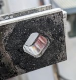
For the joint between the crankarm and spindle, I could do any design, like a spline, but splines are hard to make, so I've been making a 1/2" straight "square spline" with a pinch bolt. I attached a picture of a finished one.
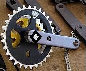
There are commercial bike cranks that use this design, and the design works fine, the problem I have is my scrap rate making the cranks and spindles. I'm about 50% success rate doing the machining on my mini-mill. I need to do something better...On one side of the cranks, I could switch to reaming out the crankarm round and pressing the shaft in, then rosette welding it, but I can't weld aluminum. And I still have to assemble the other side, so pressing isn't a total solution.
In order to fit well, the square socket should be about +0.002"-0.003" bigger than the shaft. If it's much more than 0.005" oversize, the fit is too sloppy and it takes too much pinch bolt action to tighten it down nice, plus it's susceptible to wobble. If it's 0.001, then it's usually too hard to assemble.
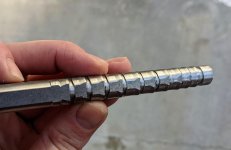
To make the square spline on the shaft, I use my square collet block and rotate it 4 times while "face milling" the flats with an end mill. It's a real challenge to hit 0.500" exactly. +/-1 0.004" is more realistic considering the tolerances from both sides add together, and that's not good enough. The vertical resolution of my mini-mill is too crude. So maybe I could try shims under the collet block instead of trying to adjust the Z-axis? Or I could switch to "side milling" the flats instead, because the X-Y resolution is much better than the Z resolution. Any other ideas? Filing to size doesn't work very well to achieve parallelism.
A bigger problem is making the square sockets. I use a 1/4" or 1/8" end-mill, but I don't have a DRO, so hitting precisely 0.500" is a challenge. I've tried counting turns on the hand-wheels, but even accounting for backlash it's easy to get lost and lose a couple thousanths. I also tried setting up dial indicators on both axes as a crude DRO but again it's just too easy to bump something or count wrong and lose a couple thousanths and scrap it.
If I "fit" the crankarms to the spindles as matched assemblies, then I have much easier time, but I'd much rather the crankarms and spindles be universal instead of trying to track them as fitted assemblies. Shouldn't it be possible to machine the squares shaft to +/- 0.001" and the sockets to +0.002"-0.004" with a manual mini-mill, or am I just wishful thinking? A 1/2" broach would probably be a good solution but they cost $250. And I still have the problem of making the shaft.
For some of my models I have an aluminum (6" x 1/2" x 1") crank-arm fitted to a 15mm diameter spindle.
For the joint between the crankarm and spindle, I could do any design, like a spline, but splines are hard to make, so I've been making a 1/2" straight "square spline" with a pinch bolt. I attached a picture of a finished one.
There are commercial bike cranks that use this design, and the design works fine, the problem I have is my scrap rate making the cranks and spindles. I'm about 50% success rate doing the machining on my mini-mill. I need to do something better...On one side of the cranks, I could switch to reaming out the crankarm round and pressing the shaft in, then rosette welding it, but I can't weld aluminum. And I still have to assemble the other side, so pressing isn't a total solution.
In order to fit well, the square socket should be about +0.002"-0.003" bigger than the shaft. If it's much more than 0.005" oversize, the fit is too sloppy and it takes too much pinch bolt action to tighten it down nice, plus it's susceptible to wobble. If it's 0.001, then it's usually too hard to assemble.
To make the square spline on the shaft, I use my square collet block and rotate it 4 times while "face milling" the flats with an end mill. It's a real challenge to hit 0.500" exactly. +/-1 0.004" is more realistic considering the tolerances from both sides add together, and that's not good enough. The vertical resolution of my mini-mill is too crude. So maybe I could try shims under the collet block instead of trying to adjust the Z-axis? Or I could switch to "side milling" the flats instead, because the X-Y resolution is much better than the Z resolution. Any other ideas? Filing to size doesn't work very well to achieve parallelism.
A bigger problem is making the square sockets. I use a 1/4" or 1/8" end-mill, but I don't have a DRO, so hitting precisely 0.500" is a challenge. I've tried counting turns on the hand-wheels, but even accounting for backlash it's easy to get lost and lose a couple thousanths. I also tried setting up dial indicators on both axes as a crude DRO but again it's just too easy to bump something or count wrong and lose a couple thousanths and scrap it.
If I "fit" the crankarms to the spindles as matched assemblies, then I have much easier time, but I'd much rather the crankarms and spindles be universal instead of trying to track them as fitted assemblies. Shouldn't it be possible to machine the squares shaft to +/- 0.001" and the sockets to +0.002"-0.004" with a manual mini-mill, or am I just wishful thinking? A 1/2" broach would probably be a good solution but they cost $250. And I still have the problem of making the shaft.
Attachments

Last edited: