To avoid these ads, REGISTER NOW!

Milling a square hole on a cheap mini mill

JackOfDiamonds

Well-known member
Joined
Jul 31, 2020
Messages
708
Location
Idaho (USA)
I know this is long but I need wisdom.

For some of my models I have an aluminum (6" x 1/2" x 1") crank-arm fitted to a 15mm diameter spindle.

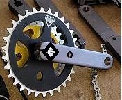
For the joint between the crankarm and spindle, I could do any design, like a spline, but splines are hard to make, so I've been making a 1/2" straight "square spline" with a pinch bolt. I attached a picture of a finished one.

There are commercial bike cranks that use this design, and the design works fine, the problem I have is my scrap rate making the cranks and spindles. I'm about 50% success rate doing the machining on my mini-mill. I need to do something better...On one side of the cranks, I could switch to reaming out the crankarm round and pressing the shaft in, then rosette welding it, but I can't weld aluminum. And I still have to assemble the other side, so pressing isn't a total solution.

In order to fit well, the square socket should be about +0.002"-0.003" bigger than the shaft. If it's much more than 0.005" oversize, the fit is too sloppy and it takes too much pinch bolt action to tighten it down nice, plus it's susceptible to wobble. If it's 0.001, then it's usually too hard to assemble.

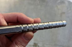
To make the square spline on the shaft, I use my square collet block and rotate it 4 times while "face milling" the flats with an end mill. It's a real challenge to hit 0.500" exactly. +/-1 0.004" is more realistic considering the tolerances from both sides add together, and that's not good enough. The vertical resolution of my mini-mill is too crude. So maybe I could try shims under the collet block instead of trying to adjust the Z-axis? Or I could switch to "side milling" the flats instead, because the X-Y resolution is much better than the Z resolution. Any other ideas? Filing to size doesn't work very well to achieve parallelism.

A bigger problem is making the square sockets. I use a 1/4" or 1/8" end-mill, but I don't have a DRO, so hitting precisely 0.500" is a challenge. I've tried counting turns on the hand-wheels, but even accounting for backlash it's easy to get lost and lose a couple thousanths. I also tried setting up dial indicators on both axes as a crude DRO but again it's just too easy to bump something or count wrong and lose a couple thousanths and scrap it.

If I "fit" the crankarms to the spindles as matched assemblies, then I have much easier time, but I'd much rather the crankarms and spindles be universal instead of trying to track them as fitted assemblies. Shouldn't it be possible to machine the squares shaft to +/- 0.001" and the sockets to +0.002"-0.004" with a manual mini-mill, or am I just wishful thinking? A 1/2" broach would probably be a good solution but they cost $250. And I still have the problem of making the shaft.
 

Attachments

  • IMG_20200420_151609091 (1).jpg
    IMG_20200420_151609091 (1).jpg
    133.9 KB · Views: 160
Last edited:
To avoid these ads, REGISTER NOW!

gorilla

Well-known member
Joined
Dec 13, 2007
Messages
1,656
If your scrap rate is 50% you need to change your design or your manufacturing methods. You have learned the capabilities of your mini mill it may be time to upgrade. A real mill and a broach would make that job easy.
 

rsanter

Well-known member
Joined
Dec 22, 2007
Messages
18,523
Location
visalia ca
There are many ways to do this.
You can broach it. If it is aluminum then you can make a broach out of lathe tool.
You can also make a nibbler if you have a manual press.

You can improve what you are doing. You can drill the 4 corners with a small bit and the do a manual operation squaring the hole. Finish with a file and done.

You can go round with a round key way. Round on the shaft and round on the hole. Then put together indexed where you want it and then drill a round hole at the intersection of the shaft and hole and then put a pin in the hole.

You can go "double D". Mill a slot with a end mill leaving the ends round. Machine two flats on the shaft. Insert and tighten
 
OP
J

JackOfDiamonds

Well-known member
Joined
Jul 31, 2020
Messages
708
Location
Idaho (USA)
There are many ways to do this.

Thank you for the suggestions.

You can broach it. If it is aluminum then you can make a broach out of lathe tool.
You can also make a nibbler if you have a manual press.

I will do some research on making a broach. The potential problem with broaching is getting the broach "clocked" accurately. This is easy on the mill but could be challenging unless both crank arms are broached at the same time together. Still doesn't solve the shaft problem though.

You can drill the 4 corners with a small bit and the do a manual operation squaring the hole. Finish with a file and done.
This is how I started, but without a filing machine or some sort of jig, it is too hard to keep the faces of the hole square to each other, flat and parallel. I actually bought the mill to improve on the file. Now my holes are square and parallel, but the challenge is getting them the right size.

You can go round with a round key way. Round on the shaft and round on the hole. Then put together indexed where you want it and then drill a round hole at the intersection of the shaft and hole and then put a pin in the hole.

Unfortunately experience suggest this will not work and neither will a square keyway. If there is any play, it will work loose and wallow.

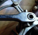
A potential option is to use a tapered pin through the crankarm perpendicular to the shaft and pulled tight with a nut (cottered). This is a long and glorious tradition actually, as seen in the picture. Tapered pins like this definitely works and I'm seriously considering it. It should be very easy to fabricate with only drilling holes, but the problem is the tapered pins tend to get seized but that's a long-term problem and can be mitigated somewhat.

You can go "double D". Mill a slot with a end mill leaving the ends round. Machine two flats on the shaft. Insert and tighten

This is an intriguing idea but I think unless the round parts fit quite closely, it would develop play. Simply milling a slot in a single operation would not match the shape of the shaft, so there's no way to make it fit well. Milling a complex D shape would be harder than milling a square, and probably impossible without CNC.
 

Attachments

  • cotters.jpg
    cotters.jpg
    16.4 KB · Views: 45

Tim in Indiana

Well-known member
Joined
Nov 1, 2018
Messages
91
Location
Indiana
I know this is long but I need wisdom.

A 1/2" broach would probably be a good solution but they cost $250. And I still have the problem of making the shaft.

You can buy a 1/2 square push broach for less than $150 on Amazon. I imagine you can find it for less if you shop around a bit.

As far as clocking it to a certain position on the part you can make a simple alignment fixture using your mill. I have done this several times with short run production parts.

Last, what about a simple round shaft with the proper size woodruff key? A woodruff key is essentially captured as long as the female part with the bore remains on the shaft.
 

VR6ix

Well-known member
Joined
Mar 24, 2013
Messages
356
Location
Onterrible, Canuckistan
A 6" long crank arm is 152.4mm (although bicycle crank arms are measured center of the spindle to center of pedal). Can you up-size to 165mm and use off-the-shelf bike parts for the crank and bottom bracket and chainrings? Or pick the right style of crank arm that's solid at the end, cut them down and drill & tap a new pedal hole? It's not home-made but could solve all your problems at once.
 

rsanter

Well-known member
Joined
Dec 22, 2007
Messages
18,523
Location
visalia ca
If you make a broach I would make a fixture that would index of the side of the arm for indexing and then will hold the broach orientation. Push through with a arbor press.

I still think the double D will work as you will still be clamping to the shaft so should not work loose
 

rsanter

Well-known member
Joined
Dec 22, 2007
Messages
18,523
Location
visalia ca
Also look up iron workers. They have square punched available and just buying the punch should be reasonable cheap, then make a fixture for it
 

Bigblue&Goldie

Well-known member
Joined
Mar 12, 2009
Messages
10,729
Location
AZ
Cool project, I'd like to see more of what you're doing. Are you using a commercially produced bottom bracket?

My opinion on the crank arms is to see what it would cost to have a broaching shop do the work. If not, maybe machine them undersized and finish by hand with a file. I'd be worried about longevity of the crank arm hole without a taper like the old square spindle bottom brackets had. Most aluminum crank arms are forged, which adds to their durability. A poor fit on a machined arm will likely quickly wallow out.
 
OP
J

JackOfDiamonds

Well-known member
Joined
Jul 31, 2020
Messages
708
Location
Idaho (USA)
I cannot use commercial bike parts because they are too big. I could copy the idea of making a square taper, but that would be even harder to make. Although you can buy 2-degree tapered end mills, so I thought about it once, but I never tried it. I think the pinchbolt design will work I just need to buy or make a broach for the square hole, and get better about making the end of the shaft accurate. Concentricity is not important so I should probably make my final mill passes on 2 sides rather than trying to mill all 4 flat sides to size.

A piece of 1/2" O-1 tool steel is $25 by itself. Do you think un-hardened mild steel would work in aluminum?
 

PugetDude

ALLIANCE MEMBER
Joined
Mar 13, 2013
Messages
22,469
Location
Superstition Mountains, AZ
I cannot use commercial bike parts because they are too big. I could copy the idea of making a square taper, but that would be even harder to make. Although you can buy 2-degree tapered end mills, so I thought about it once, but I never tried it. I think the pinchbolt design will work I just need to buy or make a broach for the square hole, and get better about making the end of the shaft accurate. Concentricity is not important so I should probably make my final mill passes on 2 sides rather than trying to mill all 4 flat sides to size.

A piece of 1/2" O-1 tool steel is $25 by itself. Do you think un-hardened mild steel would work in aluminum?

You might try case hardening.
From the Speedy Metals website:

HEAT TREATING
1018 will respond to any carburizing method and subsequent heat treatments. Case hardening results in a hard case and relatively soft core. Carburize at 1650°-1700°, oil or water quench and temper at 300°. For a hard case and tough core, the following heat treatment is suggested: Carburize at 1650°-1700°F for approximately 8 hours, cool in oven and reheat to 1400°-1450°F. Quench in water and draw at 300°-350°. Carburizing depth typically .060-.070".
 

RoninB4

Well-known member
Joined
Jul 22, 2020
Messages
3,618
Location
Under My House
It's possible to make what you're wanting (if I understand it correctly) but with those cheap mills you'll either have to measure each cut and sneak up on your dimensions or have better fixtures. Yes it will take more time sneaking up on dimensions and more math is involved but your machine/product tolerances and fixture errors come into play.

You're already running up against the limitations of your machine, this is partly why some opt for spending more money up front for more capable machinery.

Without seeing/knowing what you're using and HOW you're using it I can't be of much help but I can show you what's possible with a crappy little Chi-Wan mill. I had sold all of my larger machines and it was all I had to make a fork brace for a motorcycle. Center distances between the fork tubes was held within +/- .001 so it is possible to achieve this if you're vigilant and use proper techniques. The photos are before I further reduced the weight/mass of the brace.
 

Attachments

  • Fork Brace 1.jpg
    Fork Brace 1.jpg
    50.6 KB · Views: 61
  • Fork Brace 2.jpg
    Fork Brace 2.jpg
    43.5 KB · Views: 55
To avoid these ads, REGISTER NOW!

matt_i

Well-known member
Joined
Mar 14, 2008
Messages
10,746
Location
SE Michigan
Can you redesign slightly to bolt the arm to the face of the outer sprocket and use it to transmit the torque.

Iow go: pedal arm -> sprocket

Vs Pedal arm -> shaft -> shaft -> sprocket

As I recall from working on bikes ages ago, the tapered fit is the only way to make it stay tight for a long period. The advantage to me is that you can "blue" the taper with a sharpie marker and a very fine swiss pattern file and carefully fit the taper by removing high spots so its all bearing at once. Same process as a scraping hand would do on an old machine tool. Its entirely possible that an ID scraper would work but I personally have never tried my hand at scraping aluminum.

Its possible that a taperlock as used in machinery would also work, but I'm afraid its going to go poorly with an aluminum part (low hoop stress capability) and will easily gall instead of allowing the round taper to slide and lock tighter.

The design you see on a high end bike is well optimized and unlikely to get it better without going significantly heavier.
 
OP
J

JackOfDiamonds

Well-known member
Joined
Jul 31, 2020
Messages
708
Location
Idaho (USA)
Can you redesign slightly to bolt the arm to the face of the outer sprocket and use it to transmit the torque.

It's already like that. But that doesn't help much for the crank on the other side. Plus, only a small portion of the torque comes from the sprocket. The torque from supporting the rider is much higher and torque from the sprocket is insignificant.

As I recall from working on bikes ages ago, the tapered fit is the only way to make it stay tight for a long period.

There are three designs that work: tapered socket, tapered cotter pin, and pinchbolt. Also there are Hirth joints, but they are rare. The common theme is there can't be any play at all, so the joint must be locked up with something like a taper or pinch bolt. I'm happy with the pinchbolt design I just have trouble hitting the tolerances. Any more than a few thousands of tolerance and the pinchbolt can't really lock it well and eventually it creaks. But if it fits well then it's perfect. I think I will have to get a hydraulic press and a broach for the socket, and just be really careful when making the shaft, maybe by making some filing jigs.
 

shawhite

Well-known member
Joined
May 28, 2014
Messages
1,519
If you want a 100% success rate a rotary broach is the tool you want but it’s expensive. You can fine cheaper versions on eBay that may work good enough in aluminum.
 

APEowner

Well-known member
Joined
Oct 2, 2009
Messages
4,166
Location
Sunny, New Mexico
You should be able to get a tighter tolerance on the shaft than what you are. Side milling is one way to do it. You could also mount one of the sub $10.00 digital calipers on your Z-axis. You have a mill so you can make your own brackets.

For the hole I'd make my own broach as well as a fixture that indexes it off the long sides of the crank.
 

MushCreek

Well-known member
Joined
Jan 14, 2015
Messages
9,827
Location
Upstate South Carolina
You can get a 1/2" square HSS lathe bit for under $10. Bear in mind that you won't be able to just shove it through a round hole. Likely you'll have to mill a square hole a little undersize, and use the homemade broach to size it.

I'm sure I could hold .001" on a mini mill, but it would take forever. You have to indicate everything over and over, and sneak up on it, measuring constantly. If you're making these for a hobby, that's fine. Just take your time. If you're looking to sell them, go ahead and tool up properly. Your time is worth something. You could also price having them made for you. A wire EDM would make quick work of cutting very accurate square holes and the slot.
 
OP
J

JackOfDiamonds

Well-known member
Joined
Jul 31, 2020
Messages
708
Location
Idaho (USA)
I tried having some laser cut. The tolerances are good enough but the kerf is too rough. I never tried wire EDM.

I already have some 1/2" HSS, but I can't turn that on a lathe, and I don't have a surface grinder or anything. When I get time I will try crafting something on the bench grinder and belt sander. With that time of course I could probably do a couple holes on the mill even if I have to redo a couple...the eternal trade-off...
 
OP
J

JackOfDiamonds

Well-known member
Joined
Jul 31, 2020
Messages
708
Location
Idaho (USA)
Could you change the design to swage the male part? Knurling might be another option for an interference press fit.

I definitely am considering a semi-permanent joint for one side. Something like a close press fit+pin+loctite. Actually, I could stick with the same square joint and just make it undersize, and press it on. However, the other side needs to be removable for maintenance, so a permanent joint on one side only solves half the problem (and creates a second type of joint to make)
 

Monza Harry

Well-known member
Joined
Dec 29, 2018
Messages
1,433
Location
Windsor ON
JOD I use only Bridgeports and the off shore look alikes, [I don't have any handle time with the benchtop models] but this should be do-able with a decent mill, you will find that holding size will be easier with the end of a mill [Carbide or indexed] and the knee. If you only have a quill for a fine feed in "Z" good luck, possible put painful and slow. The other thing is your clamping slot isn't optimized from my experience, that will only pull tight on the two parallel faces, by rotating your square 90* this will improve clamping. See the added "MS-paint" add in's in the pic.
The other approach is to forge the square hole, heat the end of the crank and pound/press the crank lower shaft into it (roughed out to start of course). Messy and barbaric Yes but can be very effective. With aluminum this will require less force but can sometimes effect the material strength, which may require heat treat and a material that can be heat treated
Harry
 

Attachments

  • Bicycle crank.jpg
    Bicycle crank.jpg
    15.8 KB · Views: 29
OP
J

JackOfDiamonds

Well-known member
Joined
Jul 31, 2020
Messages
708
Location
Idaho (USA)
I've made the holes diagonal like you showed also. I think it's better but it requires a thicker crank. Also, it doesn't seem to be that much better in practice because some if the worst wobbling and creaking incidents have been with the diagonal ones. Basically if the tolerances are too loose the direction of the hole doesn't matter and if the tolerances are close, direction doesn't seem to matter either.
 
OP
J

JackOfDiamonds

Well-known member
Joined
Jul 31, 2020
Messages
708
Location
Idaho (USA)
Here's some updates with a couple attempts.

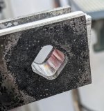
I had some parts laser cut for cheap out of 1095 and hardened them to make file-guides. This totally works, the problem is that I thought it would take like 10 minutes but it took more like an hour. The aluminum files quickly but the problem is filing the last couple of thousanths takes forever because you can't get any good file pressure, and since no file exactly matches the hole profile, you end up chasing little bumps forever. I don't even have energy to try another one, so this technique is out. But on a "stuck on a desert island with only a laser cutter" level, this would work.

Next, I made a quickie broach out of a $4 piece of key stock. There's a thousand things wrong here, not least of which it's not long enough, the key stock material is too soft and won't harden, and I don't even have a press so I pounded it through with a sledge hammer. Despite all that it sort of worked. It took me less time to make the broach AND do the broaching than filing one hole. So I'm leaning toward springing for a $200 push broach at this point.

I don't really want a square-cornered hole anyway, I'd rather have rounded corners, so my other option is spend $30 on tool steel, and make my own broach with the profile I want, and save about $150 on the broach itself. The problem is, after I make a broach out of O-1 I can totally harden it in my forge, but I don't know if it will still be sharp enough after hardening. If I coat it with boric acid before I harden it, will it still be sharp enough after hardening, or will the hardening process dull it so that it absolutely has to be ground after hardening?
 

Attachments

  • PXL_20210124_232830374_2.jpg
    PXL_20210124_232830374_2.jpg
    102.1 KB · Views: 20
  • PXL_20210127_031243132_3.jpg
    PXL_20210127_031243132_3.jpg
    86.2 KB · Views: 17
  • PXL_20210129_045647177_2.jpg
    PXL_20210129_045647177_2.jpg
    124.1 KB · Views: 17
  • PXL_20210129_051056265.jpg
    PXL_20210129_051056265.jpg
    149.2 KB · Views: 16

RoninB4

Well-known member
Joined
Jul 22, 2020
Messages
3,618
Location
Under My House
How many holes do you intend to broach? One off tooling conditions are much different than production conditions. What may work for 5-10 will usually not work well for 50. All broaches I've made are always ground after hardening. Hardening O-1 and using a hammer will likely result in a shattered broach unless tempered after hardening. Would also suggest the broach be longer than the experimental model you made AND the "gullet" between the teeth be back-cut for a sharper edge. Aluminum is gummy and clogs cutters easily, once it's packed into the "flutes" it tends to weld to itself and the workpiece. Just a suggestion.
 

PCustoms

Well-known member
Joined
Jul 23, 2011
Messages
23,454
Location
VT
Is your issue really tolerance related?

To me it looks like your lunch bolt is never going to pull that right. Try extending your slot a little past the other side of the square hole so that there is more room for everything to flex and clamp tight.

Also I would suggest a smaller endmill for tighter corners as your final cleanup passes (if you need them tighter).
 
To avoid these ads, REGISTER NOW!
Top Bottom