To avoid these ads, REGISTER NOW!

Most effective method - Multiple 3-way switches, Multiple fixtures

Makincold

Well-known member
Joined
May 3, 2013
Messages
55
Location
Mansfield, GA
So I have spent a lot of time searching here as well as other places on the Internet on how to wire a 3-way switch to multiple fixtures and I'm good with that, but I want some help with the most effective way to do this rather than just run tons of 14/3
Or talk me out of what I "think" i want to do because its not worth the trouble or expense
Want a "neat" job too, how to run the wire, not just string it across the rafters.

So I have Qty (10) florescent fixtures, each fixture has 2 ballast
I want to switch 1 ballast on each fixture so half the bulbs on each fixture
(represented with blue and green in the pic I attached)
Each (1/2) of the fixture or 1 ballast is .93A so 10 would be 9.3A
If I ran power to ALL at once that would be 18.6A

I want to run 1/2 the fixtures on a cloudy day, I have skylights but thats a lot of watts (seems like it anyway...) to run if I dont mneed them all on at once

I have doors at opposite corners of the building and the panel is in the corner with SW1 and SW3. Building is new so I don't have wires running all over the place to "pick up a hot leg" so I'm starting from scratch

Ceiling is open roof trusses (pic attached), I'll have a 2x4 between a truss and the fixture screwed to the 2x4, flush with the bottom of the truss

So is this a hair brained idea? or are there some ideas that will make an effective plan out of this?

Thanks!
 

Attachments

  • SM image003.jpg
    SM image003.jpg
    89.7 KB · Views: 71
  • SM1 image002.jpg
    SM1 image002.jpg
    85.7 KB · Views: 84
  • SM1 image001.jpg
    SM1 image001.jpg
    89.9 KB · Views: 56
To avoid these ads, REGISTER NOW!

Old Engineer

Well-known member
Joined
Jul 4, 2013
Messages
45
Since you are asking about wiring this as a 3-way, I assume you want 2 switches at each door? Each switch at each door can turn on half the lights? I'm also assuming that each fixture has 4 bulbs in it, and each ballast will control 2 bulbs?

If this is the case, it looks like you will need to run 2 sets of 14/3 to all the fixtures, then 2 sets of 14/3 from each switch box to the other. There is no other safe way to run the wires for actual 3-way switching.

But, you could do a Insteon or Z-Wave type control. With this, you only need 1 set of switches that are actually controlling the lights, from one corner of the garage. Then, the other corner are basically wireless controllers that can remotely turn on the other switches in the corner. These wireless controllers will still need power though, so you will still need to run a 14/3 wire to them. All it saves you is the second set of 14/3. But, it gives you the ability to control these lights from anywhere. These can be tied to motion sensors, a pocket controller, or even an iPhone.
 
OP
M

Makincold

Well-known member
Joined
May 3, 2013
Messages
55
Location
Mansfield, GA
Thanks for the reply
Yes, 2 switches at each door (SW1 / SW2 blue on the dwg)(SW3 / SW4 green on the dwg) each fixture actually has 3 bulbs per ballast, 6 bulbs total for the fixture
I actually have a house full of Miro RF dimmers and controls and could possibly do that here but was going hard wire rather than RF on this, but its not out of the question
Posted here to see if I was "missing the forest for the trees" on the wiring of the switches for what I wanted to do
 

wyliesdiesels

Well-known member
Joined
Aug 14, 2012
Messages
20,073
Location
Modesto, CA
Theres no way to do this other than running lots of 3 conductor cable. If u want it to look neat u could use conduit or BX/FMC.

This isnt that hard to do though:

14/2 from panel to one set of switches
14/3 between both sets of switches and then 14/3 from second set of switches to all the fixtures!

The neutral is carried on the white wire throughout the whole circuit, the travelers are red and black between the switches and the 2 switched hots are the red and black wires between the second set of switches and all the fixtures!!

Ive done commercial wiring with multiple switched banks and we always use 3 conductor BX! There just isnt a more efficient way of doing this!

Since you are asking about wiring this as a 3-way, I assume you want 2 switches at each door? Each switch at each door can turn on half the lights? I'm also assuming that each fixture has 4 bulbs in it, and each ballast will control 2 bulbs?

If this is the case, it looks like you will need to run 2 sets of 14/3 to all the fixtures, then 2 sets of 14/3 from each switch box to the other. There is no other safe way to run the wires for actual 3-way switching.

But, you could do a Insteon or Z-Wave type control. With this, you only need 1 set of switches that are actually controlling the lights, from one corner of the garage. Then, the other corner are basically wireless controllers that can remotely turn on the other switches in the corner. These wireless controllers will still need power though, so you will still need to run a 14/3 wire to them. All it saves you is the second set of 14/3. But, it gives you the ability to control these lights from anywhere. These can be tied to motion sensors, a pocket controller, or even an iPhone.

Why would u need 2 sets of 3 conductor cable between the switchs or fixtures? Thats a waste of wire! What i said above works just fine!!
 

VHF

Well-known member
Joined
Oct 27, 2008
Messages
420
Location
NW Wisconsin
Wait a second, the drawing in original post indicates 9.3A per bank of light. These are going to each need to be on their own breaker, so unless it is a MWBC, he can't be sharing the neutrals!

Here are two good, safe, and legal ways to do this:

(A.) Two separate circuits:
Two regular 15A breakers
14/2 from breaker panel to first switch location (x 2)
14/3 to second switch location (x 2) (each carries 2 travelers, 1 neutral, 1 ground)
14/2 from second switch location to each fixture (x 2)

The biggest drawback of this approach is you need to daisy chain two 14/2 cables from fixture to fixture. Do make sure the neutrals as well as the hot leads of each ballast are connected to the appropriate circuit, or you have the potential for overloading the neutral!

(B.) MWBC (Multi-Wire Branch Circuit) with shared neutral:
One 15A double-pole 240V breaker
14/3 from breaker panel to switch location 1 (x 1) (carries hot leg 1, hot leg 2, neutral, and ground)
14/3 to switch location 2 (x 2) (each carries 2 travelers, 1 switched hot, and ground)
14/3 from switch location 1 to fixtuers (x 1) (switched hot 1, switched hot 2, neutral, ground)

This approach uses less copper and keeps your lighting load balanced between the two hot legs. We are using switch location 1 as the "central hub" of the circuit, and to keep our wire count as low as possible we are avoiding running the neutral over to switch location 2. (NEC requires that a neutral be available in one but not both of the switch locations in case you ever did want to put in a smart switch that required a neutral.)

The only drawbacks I can think of is tripping the double breaker turns off all your lights, and you will have to deal with four 14/3 NM cables in a double junction box at switch location 1. But you'll only need to daisy chain a single 14/3 from fixture to fixture. I challenge anyone to come up with a better solution using standard switches and wire!
 

RickP

Well-known member
Joined
Jan 15, 2013
Messages
1,557
Location
Annapolis, MD
Those skylights should provide plenty of light for average use. You might only need the lights when you're doing real work in there. Why not put 4 lights at one end of the building on 1 switch and put the other 6 lights on the other switch? That's how I've got my garage set up, and I usually only use one side of the garage on an average day. I turn 'em all on when I'm doing work out there.

It looks like your ballasts can be wired for 240v -- that would make your wiring a lot easier and you'd only need one circuit breaker for all the lights.
 
OP
M

Makincold

Well-known member
Joined
May 3, 2013
Messages
55
Location
Mansfield, GA
Looks like this is the way I'm going:
Two separate circuits:
Two regular 15A breakers
14/2 from breaker panel to first switch location (x 2)
14/3 to second switch location (x 2) (each carries 2 travelers, 1 neutral, 1 ground)
14/2 from second switch location to each fixture (x 2)

Although the 4 and 6 fixture idea has me thinking, will be this weekend before i start so you never know :)
Thanks for the ideas everyone

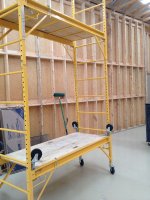
The best news is a friend let me borrow his rolling scaffold! no up and down a 12' ladder a million times
 

Attachments

  • SM2 image001.jpg
    SM2 image001.jpg
    103.5 KB · Views: 24

sands35

Well-known member
Joined
May 29, 2012
Messages
936
Location
St. Joseph, MI
Food for thought....

Are you really going to be going in and out of both doors a lot? Seams like most people will use one door 90% of the time. All you really need is a utility light at the less used door.

or

Do one bank with 3 ways and one bank with just one switch.

also....

Having a nice way to spool wire off the roll is *really* nice. Either make a rack or borrow one.
 
OP
M

Makincold

Well-known member
Joined
May 3, 2013
Messages
55
Location
Mansfield, GA
I considered that this would be something I wouldn't use very often... but it seems the "right" thing to do with 2 doors in the shop, new construction, no better time than the present kind of thing
Thinking now I may do "front of the shop" "back of the shop" like "RickP" above suggested and only split the ballast on the 2 lights in the center of the shop so both loads are equal at 9.3A each
Still on 3 ways
 

wyliesdiesels

Well-known member
Joined
Aug 14, 2012
Messages
20,073
Location
Modesto, CA
Wait a second, the drawing in original post indicates 9.3A per bank of light. These are going to each need to be on their own breaker, so unless it is a MWBC, he can't be sharing the neutrals!

Here are two good, safe, and legal ways to do this:

(A.) Two separate circuits:
Two regular 15A breakers
14/2 from breaker panel to first switch location (x 2)
14/3 to second switch location (x 2) (each carries 2 travelers, 1 neutral, 1 ground)
14/2 from second switch location to each fixture (x 2)

The biggest drawback of this approach is you need to daisy chain two 14/2 cables from fixture to fixture. Do make sure the neutrals as well as the hot leads of each ballast are connected to the appropriate circuit, or you have the potential for overloading the neutral!

(B.) MWBC (Multi-Wire Branch Circuit) with shared neutral:
One 15A double-pole 240V breaker
14/3 from breaker panel to switch location 1 (x 1) (carries hot leg 1, hot leg 2, neutral, and ground)
14/3 to switch location 2 (x 2) (each carries 2 travelers, 1 switched hot, and ground)
14/3 from switch location 1 to fixtuers (x 1) (switched hot 1, switched hot 2, neutral, ground)

This approach uses less copper and keeps your lighting load balanced between the two hot legs. We are using switch location 1 as the "central hub" of the circuit, and to keep our wire count as low as possible we are avoiding running the neutral over to switch location 2. (NEC requires that a neutral be available in one but not both of the switch locations in case you ever did want to put in a smart switch that required a neutral.)

The only drawbacks I can think of is tripping the double breaker turns off all your lights, and you will have to deal with four 14/3 NM cables in a double junction box at switch location 1. But you'll only need to daisy chain a single 14/3 from fixture to fixture. I challenge anyone to come up with a better solution using standard switches and wire!

Whoops! I missed that. Good catch!
 

Stuart in MN

Well-known member
Joined
Sep 8, 2005
Messages
23,164
Location
Minneapolis
Looks like this is the way I'm going:
Two separate circuits:
Two regular 15A breakers
14/2 from breaker panel to first switch location (x 2)
14/3 to second switch location (x 2) (each carries 2 travelers, 1 neutral, 1 ground)
14/2 from second switch location to each fixture (x 2)

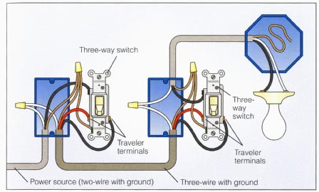
I think this is the simplest way to do it. The only 3 wire connections are between the two light switches, everything else can be done with conventional 2 wire connections.

Like this diagram, except with multiple lights.

3-way-power-at-switch.jpg
 

VHF

Well-known member
Joined
Oct 27, 2008
Messages
420
Location
NW Wisconsin
One more idea to consider would be to put in a couple of plain old porcelin screw-in sockets on 3-way switches to have as "walk through the shop lights" and then just have your main work lights switched at one location.
 

sands35

Well-known member
Joined
May 29, 2012
Messages
936
Location
St. Joseph, MI
I considered that this would be something I wouldn't use very often... but it seems the "right" thing to do with 2 doors in the shop, new construction, no better time than the present kind of thing
Thinking now I may do "front of the shop" "back of the shop" like "RickP" above suggested and only split the ballast on the 2 lights in the center of the shop so both loads are equal at 9.3A each
Still on 3 ways
OK. Suggestion from a fellow DIYer.... I've gotten into sticky spots by trying to get fancy with wiring. Might save a bit of money, but since I don't do this for a living and a project can take months, it's easy to forget what decisions have already been made. The little diagram a few posts up looks like a good idea. It makes the hard work of doing the light wiring simple.

Drop a two wire from the breaker box to the closest door. Three wire run to the next switch, then up to the lights with a 2 wire.

Having the light amp draw balanced isn't required, just don't exceed the rating for each circuit.
 
Last edited:
To avoid these ads, REGISTER NOW!

wyliesdiesels

Well-known member
Joined
Aug 14, 2012
Messages
20,073
Location
Modesto, CA
OK. Suggestion from a fellow DIYer.... I've gotten into sticky spots by trying to get fancy with wiring. Might save a bit of money, but since I don't do this for a living and a project can take months, it's easy to forget what decisions have already been made. The little diagram a few posts up looks like a good idea. It makes the hard work of doing the light wiring simple.

Drop a two wire from the breaker box to the closest door. Three wire run to the next switch, then up to the lights with a 2 wire.

Having the light amp draw balanced isn't required, just don't exceed the rating for each circuit.

The problem with is that all of the fixtures combined draw too much power!
 
OP
M

Makincold

Well-known member
Joined
May 3, 2013
Messages
55
Location
Mansfield, GA
Well I'm starting this project today!
Will decide as I go how to wire them up
Will be 3-way for sure! like the Diagram posted above (Stuart in MN) thanks
Not sure how I will combine them though
Funny enough its that cloudy overcast day i was imagining when i wanted to do half of each fixture, so I might try one out before I decide
Wish me luck!
 
OP
M

Makincold

Well-known member
Joined
May 3, 2013
Messages
55
Location
Mansfield, GA
OK!
Step #1
Ran 14/2 (qty 2) from the panel to the 3 gang outlet/switch box at the front door (want some outside lights later...)
Ran 14/3 (qty 2) from the 3 gang outlet/switch box at the back door
Will hang a light next, then to town for a breaker since the 2 (15A) breakers I THOUGHT I had don't actually exist...
 

DesertSparky57

Well-known member
Joined
Apr 12, 2013
Messages
92
Location
Las Vegas
The method of switching you describe is commonly called "A and B switching" in my area. It's widely used in office lighting. The name comes from the way the fixtures are labelled on a lighting sheet in a set of building plans, the A or B denote which switch in that particular room a specific fixture is to be loaded on.

By far, the most common way I've seen A and B switching done is to take a single circuit to your switches then split the hot amongst your switches and use 3 conductor+ground wiring to connect your lights so you can hook one ballast to black/white and the other to red/white. 3 way or not it works the same.

To me it seems like the 15A circuit is causing you some hassle. Is it necessary or required in your area to only use 15A circuits for lighting?? One 20A'er would have you covered right?? Twice as much 14 or half as much 12??

Maybe I'm way off here? Why make it more confusing with 2 circuits? Twice as much wiring up high, more connectors more wire nuts and a much fuller fixture as well... Each fixture is going to have 4 whips in it??? That just plain ***** man!! LoL!

Maybe some all knowing sparky can come along and learn me a thing or two... I'll admit I'm heavily favored towards industrial and away from residiential wiring but this just seems whack to me, I would never recommend to run 2 circuits when you can run 1 instead :)
 

AndyA

Well-known member
Joined
May 23, 2011
Messages
514
Location
Texas Near Dallas
To me it seems like the 15A circuit is causing you some hassle. Is it necessary or required in your area to only use 15A circuits for lighting?? One 20A'er would have you covered right?? Twice as much 14 or half as much 12??

I'm no electrician, but I think common switches will also limit him to 15A. 20A switches may be available.

Instead of having 2 switches that give you "half brightness" and "full brightness", I think I'd rather have it wired in zones. There's no point in lighting up the whole shop when you're only working in a portion of it.

I'd also like the idea of having a single light for "walk through". This is the light I'd wire a switch at each door. The bulk of the lights I'd be ok having to walk through the shop to turn on. You're going to turn them on, work for a few hours and turn them off. You won't be flipping them off and on like a disco!

I can also see the need for single lights above work areas (toolbox, bench, drill press, etc, etc). These are easy to wire since you put the switch right by the work area.
 
OP
M

Makincold

Well-known member
Joined
May 3, 2013
Messages
55
Location
Mansfield, GA
Well for better of for worse its "front" zone and "rear" zone
3-way switches , 2 - 15A circuits
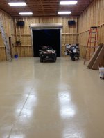
Light is great! I mad a good choice on fixtures and lamps to go with them
Pics in the morning, been a long day!
Thanks for all the post and ideas
 

DesertSparky57

Well-known member
Joined
Apr 12, 2013
Messages
92
Location
Las Vegas
Nice! Good and bright!

Simple switching is often the most useful as well, great looking shop by the way, now you just need to get it dirty.
 

VHF

Well-known member
Joined
Oct 27, 2008
Messages
420
Location
NW Wisconsin
...I would never recommend to run 2 circuits when you can run 1 instead :)
In this case, running a single single circuit wasn't an option. With each bank drawing 9.3A (for a total of 18.6A), even with a 20A circuit the 80% rule for continuous loads would be exceeded.

Sounds like he ended up with a good solution he is happy with.
 

wyliesdiesels

Well-known member
Joined
Aug 14, 2012
Messages
20,073
Location
Modesto, CA
The method of switching you describe is commonly called "A and B switching" in my area. It's widely used in office lighting. The name comes from the way the fixtures are labelled on a lighting sheet in a set of building plans, the A or B denote which switch in that particular room a specific fixture is to be loaded on.

By far, the most common way I've seen A and B switching done is to take a single circuit to your switches then split the hot amongst your switches and use 3 conductor+ground wiring to connect your lights so you can hook one ballast to black/white and the other to red/white. 3 way or not it works the same.

To me it seems like the 15A circuit is causing you some hassle. Is it necessary or required in your area to only use 15A circuits for lighting?? One 20A'er would have you covered right?? Twice as much 14 or half as much 12??

Maybe I'm way off here? Why make it more confusing with 2 circuits? Twice as much wiring up high, more connectors more wire nuts and a much fuller fixture as well... Each fixture is going to have 4 whips in it??? That just plain ***** man!! LoL!

Maybe some all knowing sparky can come along and learn me a thing or two... I'll admit I'm heavily favored towards industrial and away from residiential wiring but this just seems whack to me, I would never recommend to run 2 circuits when you can run 1 instead :)

2 lighting circuits is better because when on 1 circuit, IF the CB trips, then youre in the dark and tripping over stuff trying to find your way to the panel!
 

Delta74

Well-known member
Joined
May 6, 2011
Messages
320
Location
Peachland B.C. Canada
not up on the NEC, but the CEC usually allows ** greater then 80% circuit loading for lighting loads of florescent lights and some other fixed lighting loads as in not incadescant where you can swap a 100 watt for the 60 that was in it.

fine print usually means the breaker MUST be rated for 100% continuous use, the panel as well, most industrial or Spec grade switches will handle 20 amps, the cheap home depot 49 cent ones wont.

an option for you when doing the 3 way switches, run the circuits to a box some where , and come from the box to the lights depending on how you want to wire and switch them. anyway good luck on the project. and ignore the nay sayer's I would have 4 switches if the shop was large enough, half like your doing, and every second light per switch.
 
To avoid these ads, REGISTER NOW!
Top Bottom