To avoid these ads, REGISTER NOW!

Motor Starter Wire Sizing

bczygan

Well-known member
Joined
Nov 4, 2009
Messages
22,002
Location
DETROIT! Arsenal of Scrappers
OK,

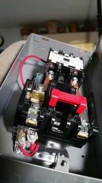
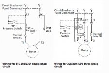
So I'm starting to understand wiring of my 5HP 1PH motor on my compressor.

I'm using #10 THHW in PVC conduit to the motor starter, L1 and L2, and the same coming out from the starter, T1 and T2, going to the motor.

The starter is a Square D 8911DPSG32V09.

It comes with 2 red wires going from L2 to one side of the overload and from the other side of the overload to the coil. The size of these wires is not marked.

If I understand this correctly, I need a wire from L1 to the coil.

Then I need a connection for the pressure switch and I also want one for an on/off switch.

2 questions:

Can I cut these 2 things into any one, or even two, of the three wires?

And what size and type do these wires need to be? This is 240V.

Bill

Bonus questions:

What are good terminals and crimpers.

What switch? I would prefer red and green push button if not too expensive.

What gets grounded, and where.
 

Attachments

  • 20170924_153037_1506281502143_resized.jpg
    20170924_153037_1506281502143_resized.jpg
    144.8 KB · Views: 44
  • 20170924_153044_1506281499708_resized.jpg
    20170924_153044_1506281499708_resized.jpg
    142.1 KB · Views: 38
Last edited:
To avoid these ads, REGISTER NOW!

mm08822

Well-known member
Joined
Jan 13, 2012
Messages
5,910
Location
NJ
From L1 run to on/off switch, from that switch to ps, from ps to A1 on coil.
Use #14. There is no green/red pb's as this is a 2wire control setup.

Make sure the overload heaters are sized properly.

Thefe is nothing to ground in this control circuit except metal hardware components.
 

manwithtools

ALLIANCE MEMBER
Joined
Aug 24, 2015
Messages
13,823
Location
Lebanon, TN
Post a picture of the wiring diagram that is inside the starter, I'm too lazy to look it up today. The schematic should answer all your questions, but we can help explain it. The wires you are referring to are control wires. I believe 14ga minimum is required on a dedicated motor circuit such as you have.
 
Last edited:

manwithtools

ALLIANCE MEMBER
Joined
Aug 24, 2015
Messages
13,823
Location
Lebanon, TN
From L1 run to on/off switch, from that switch to ps, from ps to A1 on coil.
Use #14. There is no green/red pb's as this is a 2wire control setup.

Make sure the overload heaters are sized properly.

Thefe is nothing to ground in this control circuit except metal hardware components.


Correct, or you could do away with the on/off switch and only use the pressure switch, which is the way they are typically equipped form the factory. If you are using the on/off switch, it's a 240 volt circuit that is being switched, be sure your on/off switch is rated for that voltage.
 

sberry

Banned
Joined
Jun 18, 2005
Messages
35,747
Location
Brethren, Michigan
Depending on the breaker that may be used I might be tempted to use 12. I cant recall exactly but the NEMA listing may be 14 @ 40A for control but??????????????
The whole machine gets grounded. Screw the ground wire to the enclosure where the power comes in.
 
Last edited:
OP
B

bczygan

Well-known member
Joined
Nov 4, 2009
Messages
22,002
Location
DETROIT! Arsenal of Scrappers
Overload heater is sized properly as a B40.

Branch circuit will be #10 THHN/THWN with a 60A breaker.

So find places on the motor starter and motor junction box for grounding? But not on the rest of the compressor or pressure switch?

Bill
 

mm08822

Well-known member
Joined
Jan 13, 2012
Messages
5,910
Location
NJ
Overload heater is sized properly as a B40.

Branch circuit will be #10 THHN/THWN with a 60A breaker.

So find places on the motor starter and motor junction box for grounding? But not on the rest of the compressor or pressure switch?

Bill

The B40 is from the ol heater table in the motor starter cover using the fla's of your motor?

A 60a cb will require #12's for the control ckt unless you provide additional ocp for the control ckt. #14 only good up to 45a cb in motor power ckt. #12 can be used with up to 100 motor power ckt.

The on/off switch/enclosure needs to be grounded and the pressure switch too - anything metallic in the control ckt hardware.

And yes the compressor feed egc needs to be terminated in the motor starter. The enclosure needs to be mechanically secured/bonded to the compressor frame/tank.
 
Last edited:
OP
B

bczygan

Well-known member
Joined
Nov 4, 2009
Messages
22,002
Location
DETROIT! Arsenal of Scrappers
The B40 is from the ol heater table in the motor starter cover using the fla's of your motor?

Yes, The B40 is from the cover chart and based on the 25A on the motor nameplate.


attachment.php


25A x 1.15 is 28.75. B 40 is 26.2-29.6. Or should it be based on 125%?


A 60a cb will require #12's for the control ckt unless you provide additional ocp for the control ckt. #14 only good up to 45a cb in motor power ckt. #12 can be used with up to 100 motor power ckt.

How can I tell what the size of the 2 existing control circuit wires are?


The on/off switch/enclosure needs to be grounded and the pressure switch too - anything metallic in the control ckt hardware.

And yes the compressor feed egc needs to be terminated in the motor starter. The enclosure needs to be mechanically secured/bonded to the compressor frame/tank.

Motor starter will be attached to the mounting plate on the tank.

Does a flexible metallic sheath create a bond between pressure switch, motor starter and motor junction box? Do I still need ground wire through this? Will attaching the switch to the motor starter ground it? Or is it better practice to run a ground to each component?

If I use plastic conduit between the pressure switch and motor starter, then it will need a ground wire, right? Same between motor JB and motor starter?


See questions above.

Bill
 
Last edited:
OP
B

bczygan

Well-known member
Joined
Nov 4, 2009
Messages
22,002
Location
DETROIT! Arsenal of Scrappers
So I think I have it figured out.

Tell me if I'm wrong....and why.

Existing control wires go from O/L to L2 and also from O/L to the A1 coil terminal.

All I need to do is add a control wire between L1 and the A2 coil terminal. In that line I will insert wiring connecting the pressure switch and a manual switch.

#10 in to L1 and L2 and ground to box.

#10 out from T1 and T2 to motor.

Flexible metal conduit between motor controller and pressure switch and motor grounds them and the compressor/tank.

Control wiring stranded #12 or #14.

Right?

Bill
 
OP
B

bczygan

Well-known member
Joined
Nov 4, 2009
Messages
22,002
Location
DETROIT! Arsenal of Scrappers
So I called the Mfg.

It helped me figure things out. It doesn't matter which power is connected to which coil terminal.

The O/L, pressure switch and switch are all in a loop.

Start at one of the power ins and go to a coil. Loop around by going from the other coil terminal to the second power terminal.

Then insert the three switches (OL is a switch) somewhere in the two loops.

In my case, one side has the O/L and the other has the other two switches.

The one on the left:


Sound good?

Bill
 

Attachments

  • page_2_diagram_-_Copy.jpg
    page_2_diagram_-_Copy.jpg
    56.6 KB · Views: 27
  • 1PhWiring.jpg
    1PhWiring.jpg
    145.5 KB · Views: 27
Last edited:

matt_i

Well-known member
Joined
Mar 14, 2008
Messages
10,726
Location
SE Michigan
Diagrams posted above look good to me. Its all 1 rung on a ladder logic diagram with all of those elements in series and no particular order....although the overload is usually diagrammed next to the coil to avoid extraneous wire usage.
 
OP
B

bczygan

Well-known member
Joined
Nov 4, 2009
Messages
22,002
Location
DETROIT! Arsenal of Scrappers
Diagrams posted above look good to me. Its all 1 rung on a ladder logic diagram with all of those elements in series and no particular order....although the overload is usually diagrammed next to the coil to avoid extraneous wire usage.


It took me a few days of looking at all the diagrams and YouTube videos to come to the same conclusion. I'm a little slow....

Now I need to know who makes good terminals and crimp tools, so I can wire it all up.

Bill
 

sberry

Banned
Joined
Jun 18, 2005
Messages
35,747
Location
Brethren, Michigan
A lot of this may not require crimp terminals, already has lugs in the equipment. Its not a law that says that you got to use every fitting they ever invented. A lot of times not only isn't it needed but it actually adds problems. I went to a well not to long ago where a couple crimps gave it up. They may have been needed due to spades, I dont recall now but if its listed for wrapping a wire around it then that's the way I do it. I cant ever recall having a problem with a secure wrapped wire. Spades,,, lots.
 
Last edited:
OP
B

bczygan

Well-known member
Joined
Nov 4, 2009
Messages
22,002
Location
DETROIT! Arsenal of Scrappers
A lot of this may not require crimp terminals, already has lugs in the equipment. Its not a law that says that you got to use every fitting they ever invented. A lot of times not only isn't it needed but it actually adds problems. I went to a well not to long ago where a couple crimps gave it up. They may have been needed due to spades, I dont recall now but if its listed for wrapping a wire around it then that's the way I do it. I cant ever recall having a problem with a secure wrapped wire. Spades,,, lots.

L1 and L2, as well as T1 and T2, all have a place to stick the wires straight in.

A1 and A2 (Coil terminals) have spade connections.

Pressure switch has straight in connections.

Switch will probably have spades.

Time to learn about sizes, types and makes.

Bill
 

sberry

Banned
Joined
Jun 18, 2005
Messages
35,747
Location
Brethren, Michigan
This wont require a 60 breaker. Because you can doesn't mean you should or need to. Use a 40. I got one on a 30, never tripped. Got another one on a 30, worked forever till something actually went wrong and tripped like it should. It may have tripped a 50, who knows but a breaker a little closer to the actual demand isn't a bad thing. As for the spades, remember the control wires only carry small current, the only reason they need to be sized up is for short circuit interruption,,, if it faults the wire needs to be rated for it.
And,,, noooooooo its not 12 or 14 with 60, its 12. With 40 it could be 12 or 14.
 
Last edited:
OP
B

bczygan

Well-known member
Joined
Nov 4, 2009
Messages
22,002
Location
DETROIT! Arsenal of Scrappers
This wont require a 60 breaker. Because you can doesn't mean you should or need to. Use a 40. I got one on a 30, never tripped. Got another one on a 30, worked forever till something actually went wrong and tripped like it should. It may have tripped a 50, who knows but a breaker a little closer to the actual demand isn't a bad thing. As for the spades, remember the control wires only carry small current, the only reason they need to be sized up is for short circuit interruption,,, if it faults the wire needs to be rated for it.
And,,, noooooooo its not 12 or 14 with 60, its 12. With 40 it could be 12 or 14.

Thank You!

I get what you say about a 30A. I have it hooked direct to one right now.

The circuit allows 250% of the motor plate FLA, which is 25A. That would be a 70A breaker. They are $51.

A 60A is $15.50. So is a 40A. 50A and 30A are $15.

So I'm using 10AWG with the 60A breaker for the circuit (28FLA from the chart x 1.25 =35A. Limited to 75 degree wire by the breaker, so #10THHN/THWN). No derating for ambient temp. Putting it in conduit with ground wire, of course. Have some 10AWG for the control wires too, although the 2 that are already in the motor starter are smaller. Red wires for control and red and black ones for power?

Right?

Bill
 
Last edited:

mm08822

Well-known member
Joined
Jan 13, 2012
Messages
5,910
Location
NJ
Is the 30A breaker able to hold during startup of the compressor or have you not run it yet?
If the 30 holds leave it alone. If it doesn’t or occasionally trips, consider the 45a cb.

A 45a cb will allow you to run #14’s in the control circuit.
A 60a cb forces you into 12’s for the control circuit – 14’s are easier to run.
I would not even consider 10’s for the control circuit.

The two factory wires used for the O/L are probably 16’s. I can see printing on the conductors in your pics. Read the print. You will probably have to replace these to 14’s or 12’s.

The B40 heater should be determined from the instructions in the heater chart in the enclosure by the mfr once you know the motor FLA’s and the service factor. Also if the starte and motor were in different temperature locations (not your case.) As best I can tell you have the correct size, but for the wrong reasons. Read the instructions accompanying the heater chart.

Using red wire for control is typical but not mandatory.

The convention used with NEMA starters is to have the overload contacts to the “right” of the coil by themselves.

Put the on/off switch and PS on the other side of the coil. If your PS has a built in on/off lever, then maybe you can forego the separate on/off switch ( unless of course you want it remote from the compressor).

See the attached..........
Comp_Hookup_1.jpgComp_Hookup_2.jpg
Comp_Hookup_3.jpgComp_Hookup_4.jpg
 
Last edited:

matt_i

Well-known member
Joined
Mar 14, 2008
Messages
10,726
Location
SE Michigan
Crimpers, I use Channellock 909s. There are also Thomas & betts, I feel certain Klein makes a pair and Sta-Kon I think also has pliers.

Panduit has reasonable terminals, I like their BSH- series heat shrink adhesive **** splices, Sta-Kon should have terminals, 3M also I believe, probably many others. Most of my drawer stock is old K-S terminals which are "extra heavy". The standard terminals of today are made of metal stock that's thinner and is irritating when they bend out of the way under minimal pressure. I haven't resolved this problem but will have to someday when my stock runs out.
 
OP
B

bczygan

Well-known member
Joined
Nov 4, 2009
Messages
22,002
Location
DETROIT! Arsenal of Scrappers
Is the 30A breaker able to hold during startup of the compressor or have you not run it yet?
If the 30 holds leave it alone. If it doesn’t or occasionally trips, consider the 45a cb.

A 45a cb will allow you to run #14’s in the control circuit.
A 60a cb forces you into 12’s for the control circuit – 14’s are easier to run.
I would not even consider 10’s for the control circuit.

The two factory wires used for the O/L are probably 16’s. I can see printing on the conductors in your pics. Read the print. You will probably have to replace these to 14’s or 12’s.

The B40 heater should be determined from the instructions in the heater chart in the enclosure by the mfr once you know the motor FLA’s and the service factor. Also if the starte and motor were in different temperature locations (not your case.) As best I can tell you have the correct size, but for the wrong reasons. Read the instructions accompanying the heater chart.

Using red wire for control is typical but not mandatory.

The convention used with NEMA starters is to have the overload contacts to the “right” of the coil by themselves.

Put the on/off switch and PS on the other side of the coil. If your PS has a built in on/off lever, then maybe you can forego the separate on/off switch ( unless of course you want it remote from the compressor).

See the attached..........
Comp_Hookup_1.jpgComp_Hookup_2.jpg
Comp_Hookup_3.jpgComp_Hookup_4.jpg

mm08822,

That is some damn beautiful work you did there, and fully diagrams and explains it all.

Best explanation on the internet!!!

Thank you for taking the time and making the effort and doing it all! It will help people (And me) in the future!

And darn if you didn't spot labeling on the wiring in the photo! It IS AWG14!


Bill
 
Last edited:
To avoid these ads, REGISTER NOW!
OP
B

bczygan

Well-known member
Joined
Nov 4, 2009
Messages
22,002
Location
DETROIT! Arsenal of Scrappers
2 more dumb newbie questions:

It seems that the machine screw holding this starter in the cabinet is metric.

M5x.8 to be exact.

Is that true?

Are the fasteners in these enclosures metric? Probably not........?

Would the machine screw for holding the ground to the enclosure also be metric? It seems an M4x.7 would go there. Don't know if it's tapped or not.

And when connection of wires, like ground wires to an enclosure, must be bolted, does a machine screw, threaded through the wall of the enclosure qualify?

Bill
 
Last edited:

alfredeneuman

Well-known member
Joined
Mar 3, 2011
Messages
4,580
Location
Fullerton, CA
And when connection of wires, like ground wires to an enclosure, must be bolted, does a machine screw, threaded through the wall of the enclosure qualify?

It's addressed in NEC 250.8 (A)
(A) Permitted Methods.
.............................
(5) Machine screw-type fasteners that engage not less than
two threads or are secured with a nut
(6) Thread-forming machine screws that engage not less
than two threads in the enclosure.

It says nothing about the size of the screw, but factory made ground screws are 10-32 X 5/8". Often light fixtures are supplied with 8/32 screws pre-installed.

Sheet metal screws are expressly prohibited from being used.
 
Last edited:
OP
B

bczygan

Well-known member
Joined
Nov 4, 2009
Messages
22,002
Location
DETROIT! Arsenal of Scrappers
It's addressed in NEC 250.8 (A)
(A) Permitted Methods.
.............................
(5) Machine screw-type fasteners that engage not less than
two threads or are secured with a nut
(6) Thread-forming machine screws that engage not less
than two threads in the enclosure.

It says nothing about the size of the screw, but factory made ground screws are 10-32 X 5/8". Often light fixtures are supplied with 8/32 screws pre-installed.

Sheet metal screws are expressly prohibited from being used.

I love it when the pros chime in with the real skinny and cite chapter and verse!

Bill
 

mm08822

Well-known member
Joined
Jan 13, 2012
Messages
5,910
Location
NJ
M5 x 0.8 and 10-32 are the most commonly confused fasteners between SAE and metric systems....they are the very closest that I've ever found.

Yes you so are right. I never gave it a thought, but I checked on my thread gauges. 5mm screw and #10 screw are virtually same diameter.

And the thread pitch is sooooo close:
25.4mm/inch / 0.8 mm/thread = 31.75 threads/inch. Way too easy to make fit!
 

mm08822

Well-known member
Joined
Jan 13, 2012
Messages
5,910
Location
NJ
2 more dumb newbie questions:

It seems that the machine screw holding this starter in the cabinet is metric.

M5x.8 to be exact. Is that true? matt answered that - 10-32.

are the fasteners in these enclosures metric? Probably not........? a nema starter is all sae hardware last i knew. Iec is a different story.

would the machine screw for holding the ground to the enclosure also be metric? It seems an m4x.7 would go there. Don't know if it's tapped or not.
doubt it. The hole could be tapped but more likely needs a thread cutting screw. I suggest you use a small grounding bar instead of putting several ground wires on one bolt. See below.

and when connection of wires, like ground wires to an enclosure, must be bolted, does a machine screw, threaded through the wall of the enclosure qualify?

Bill
Screen Shot 09-28-17 at 01.26 AM.JPG Screen Shot 09-28-17 at 01.31 AM.JPG
 

matt_i

Well-known member
Joined
Mar 14, 2008
Messages
10,726
Location
SE Michigan
Yes you so are right. I never gave it a thought, but I checked on my thread gauges. 5mm screw and #10 screw are virtually same diameter.

And the thread pitch is sooooo close:
25.4mm/inch / 0.8 mm/thread = 31.75 threads/inch. Way too easy to make fit!

Yes, for just a couple of threads like in a grounding app in a metal box then its probably not noticeable. But where you have more than about 4-5 continuous threads then its going to jam.

Don't ask how I know this :) I got into modifying some details on a machine which is supposed to be built to a standard of "all metric coarse thread fasteners for general use" but lo and behold when my M5 started to jam by hand and my metric allen wrenches don't fit the existing internal hexes, then the light bulb started to go on.
 

mm08822

Well-known member
Joined
Jan 13, 2012
Messages
5,910
Location
NJ
I'm going to go with the 40A breaker so I can use 14AWG control wiring.

Where is the section on sizing control wiring?

Bill

You can use up to a 45A CB for copper conductors. NEC 430.72 / Table 430.72(B).

You never answered a previous q from an earlier post. Did the 30A hold or have you not turned it over yet?
 
OP
B

bczygan

Well-known member
Joined
Nov 4, 2009
Messages
22,002
Location
DETROIT! Arsenal of Scrappers
I have a bunch of red 12AWG. Can I use for control wiring? I suppose all the control wiring would have to be 12 then.

And I have some black and some red #10. Can I use black for one hot and red for the other?

Bill
 

mm08822

Well-known member
Joined
Jan 13, 2012
Messages
5,910
Location
NJ
I have a bunch of red 12AWG. Can I use for control wiring? I suppose all the control wiring would have to be 12 then.

And I have some black and some red #10. Can I use black for one hot and red for the other?

Bill

You can use the 12 but make sure it fits all termination points first. All control wiring same size would be preferred for consistency.

Sure use red and black 10's. And you have 10 green?

All of this wiring should be stranded b/c of vibration.
 
OP
B

bczygan

Well-known member
Joined
Nov 4, 2009
Messages
22,002
Location
DETROIT! Arsenal of Scrappers
You can use the 12 but make sure it fits all termination points first. All control wiring same size would be preferred for consistency.

Sure use red and black 10's. And you have 10 green?

All of this wiring should be stranded b/c of vibration.

I will pick up some #14 red for the rest of the control wiring, so I can just leave the 2 wires that are in there already.

A 40A breaker is readily available, and reasonable cost, so will use that.

I have lots of #12 green, but no #10, so will have to pick up some.

All is stranded, of course.

And thank you so much, for holding my hand through all this. It will surely be a resource for others.

Bill
 

alfredeneuman

Well-known member
Joined
Mar 3, 2011
Messages
4,580
Location
Fullerton, CA
You only need the larger (#14) wire for the portion that's external to the motor starter enclosure (such as the pressure switch), not the jumper wires on the starter itself.
 
OP
B

bczygan

Well-known member
Joined
Nov 4, 2009
Messages
22,002
Location
DETROIT! Arsenal of Scrappers
You only need the larger (#14) wire for the portion that's external to the motor starter enclosure (such as the pressure switch), not the jumper wires on the starter itself.

Well, since the existing jumper wires inside the stater enclosure are 14's, it wouldn't bother me to make the one to the pressure switch AND the on/off switch both 14's. I'll probably make the on/off switch remote anyway, as the compressor will be on a porch.

I understand now, how the power wiring is sized, and the breaker.

But still a little confused about how the control wiring is sized.

Bill
 

mm08822

Well-known member
Joined
Jan 13, 2012
Messages
5,910
Location
NJ
Well, since the existing jumper wires inside the stater enclosure are 14's, it wouldn't bother me to make the one to the pressure switch AND the on/off switch both 14's. I'll probably make the on/off switch remote anyway, as the compressor will be on a porch.

I understand now, how the power wiring is sized, and the breaker.

But still a little confused about how the control wiring is sized.

Bill

Do you have a code book and read NEC 430.72 / Table 430.72(B)? There's your answer - 3 threads ago from me.

When is this thing going to make some noise? Tic Toc.......
 
To avoid these ads, REGISTER NOW!
Top Bottom