To avoid these ads, REGISTER NOW!

MP&C Shop Projects

OP
M

MP&C

Well-known member
Joined
Oct 21, 2009
Messages
4,396
Location
Leonardtown, MD
Thanks Tim!

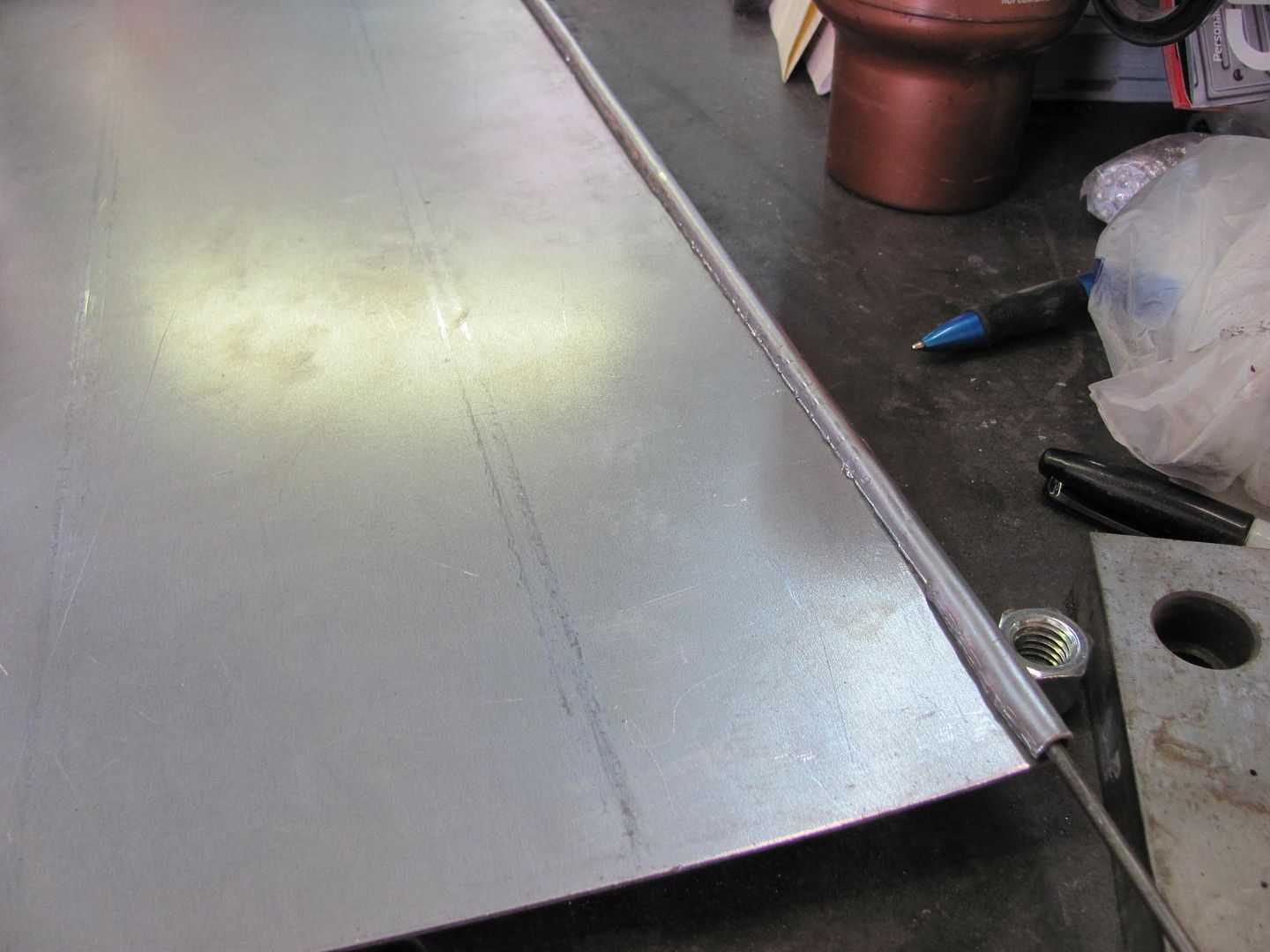
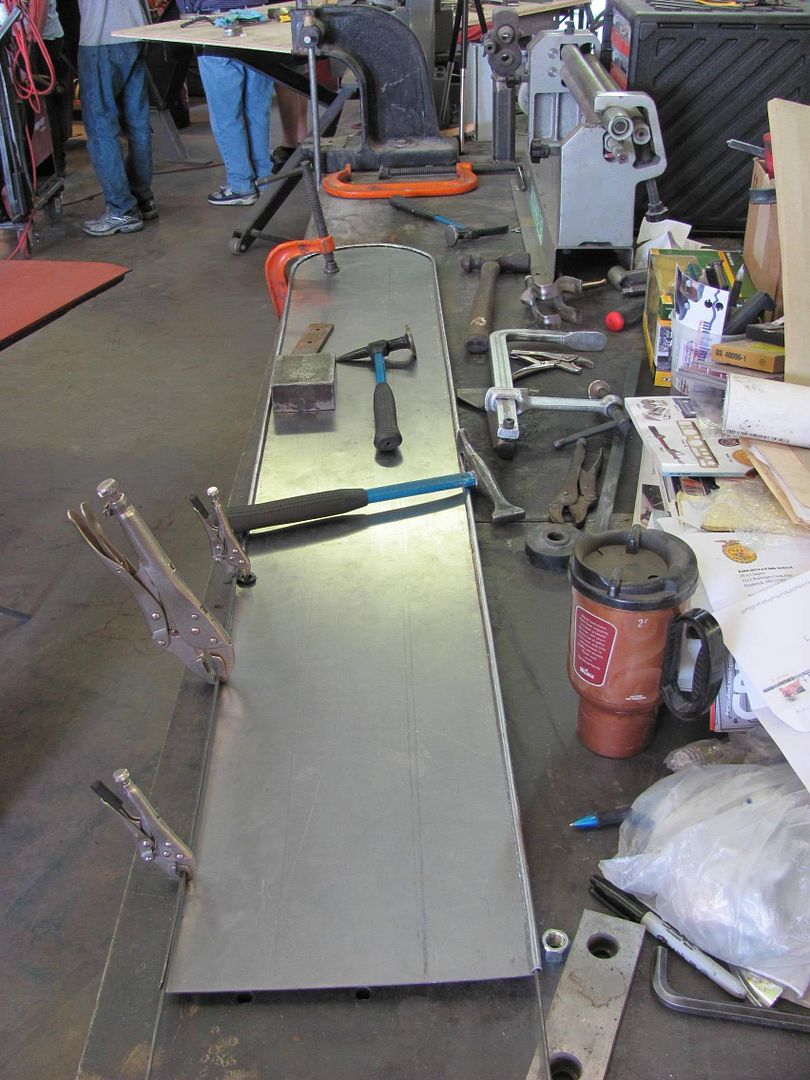
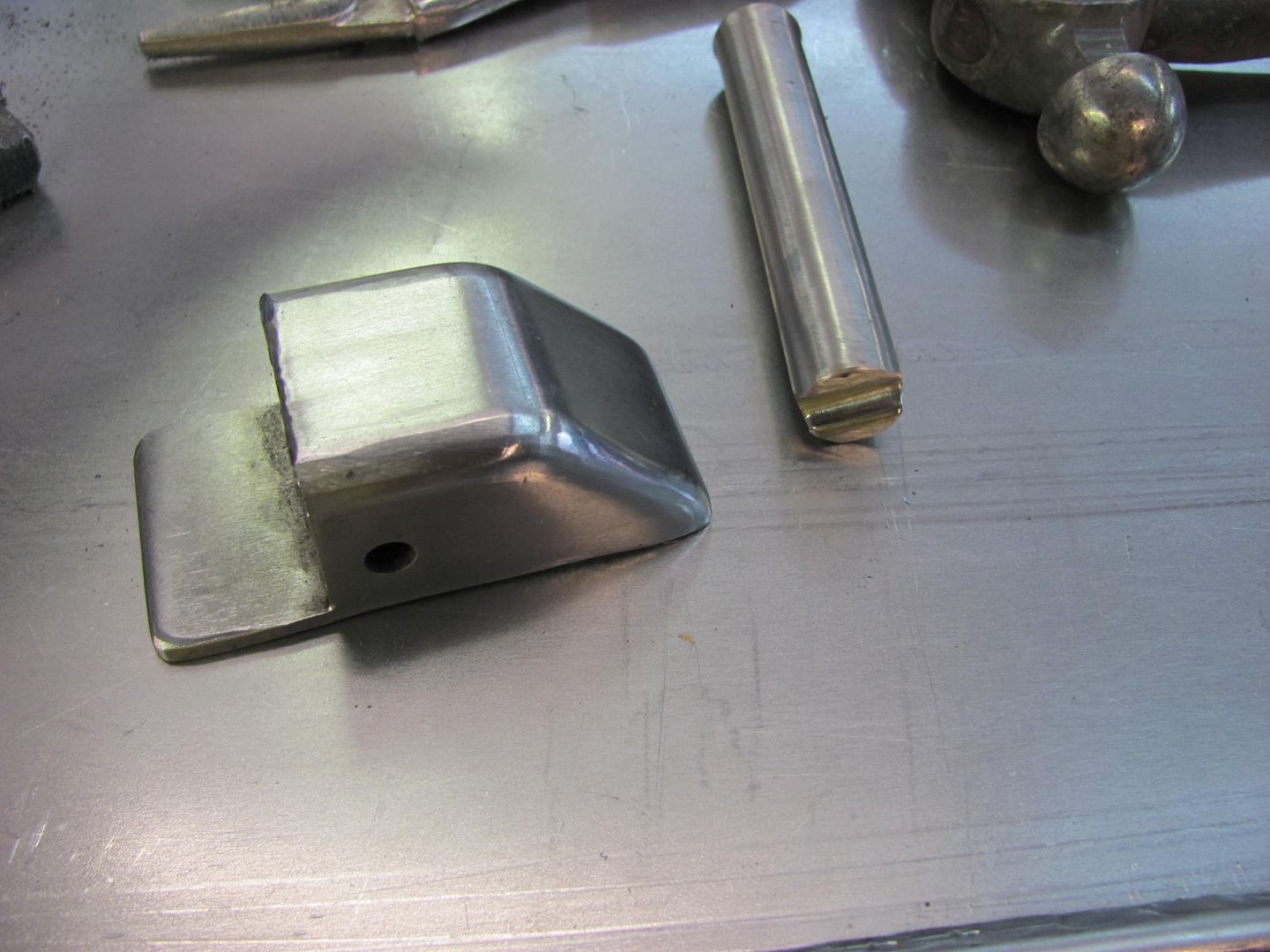
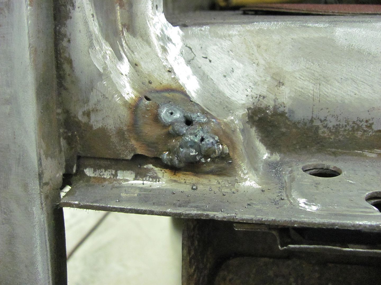
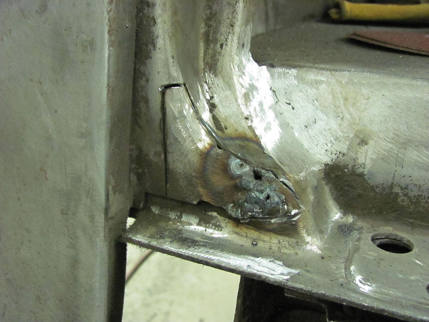
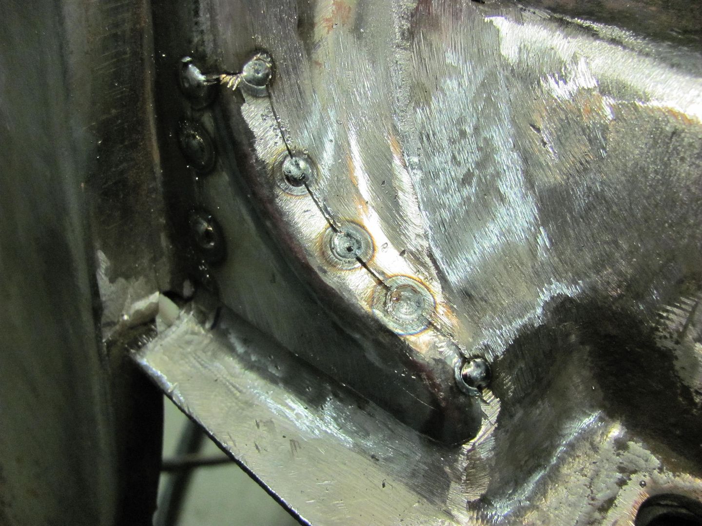
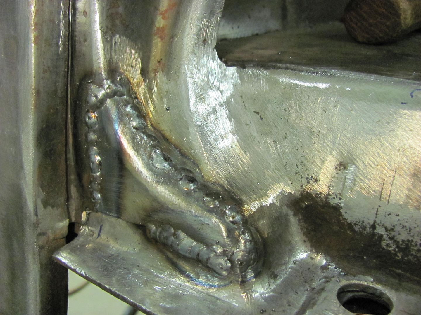
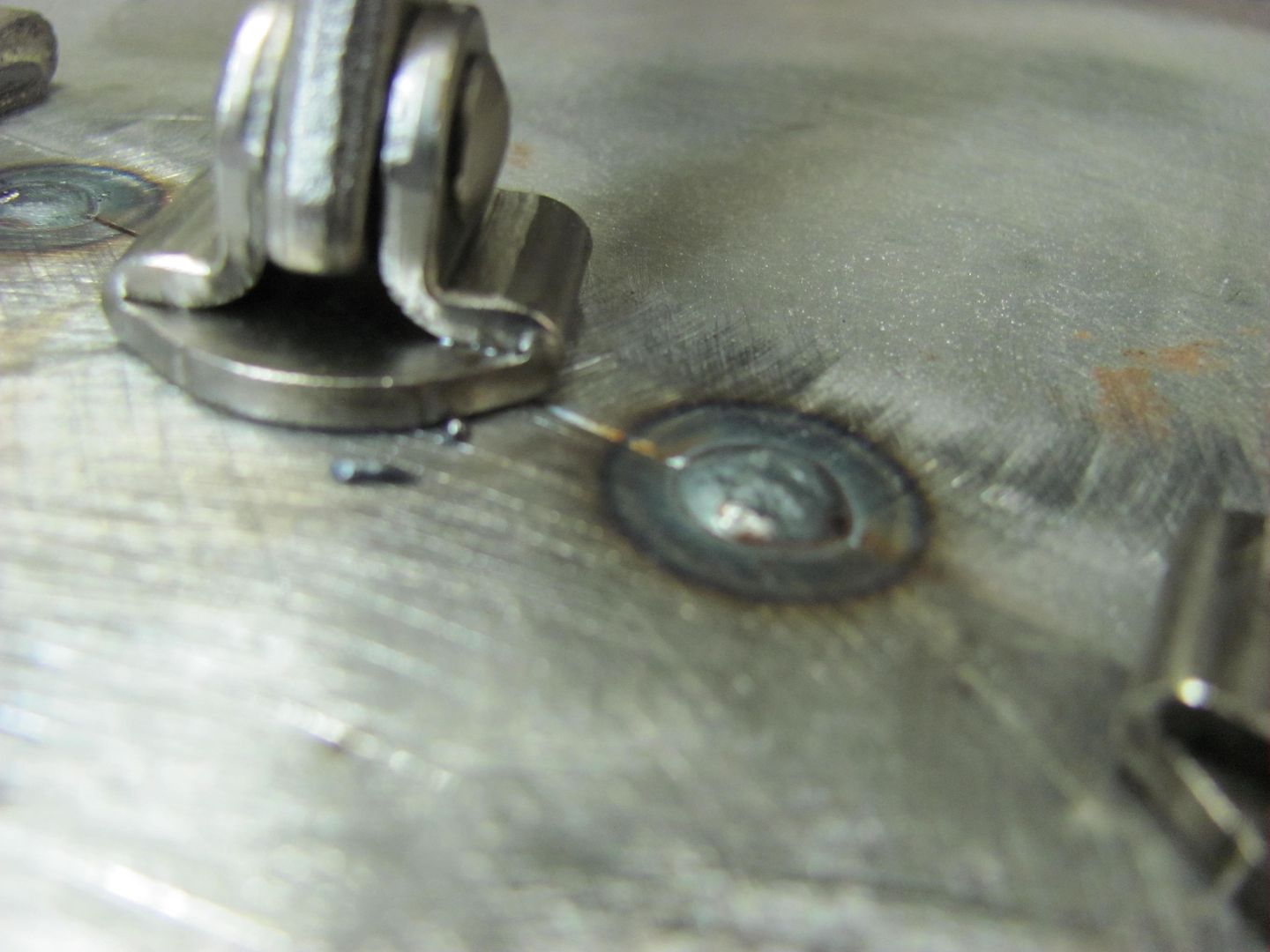
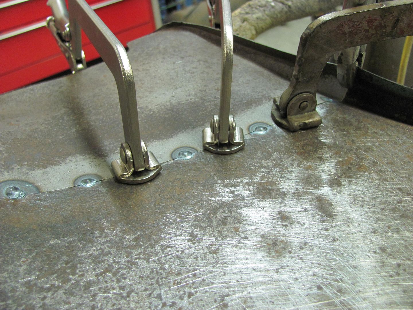
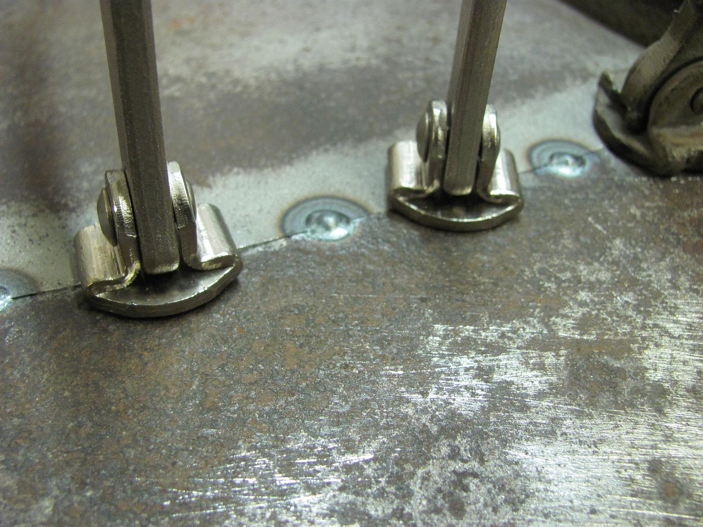
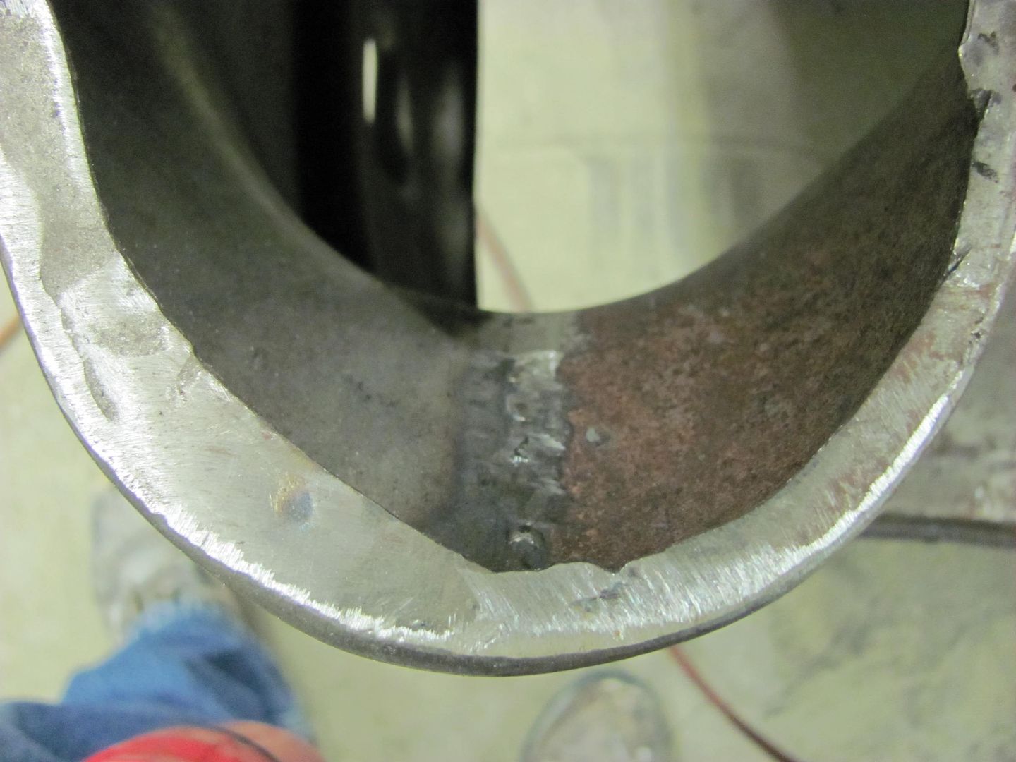
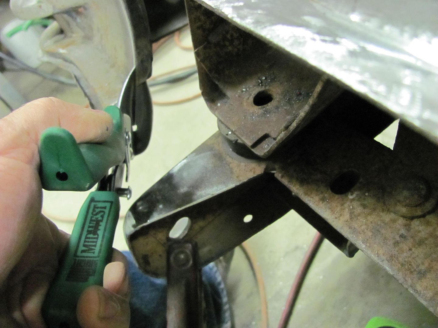
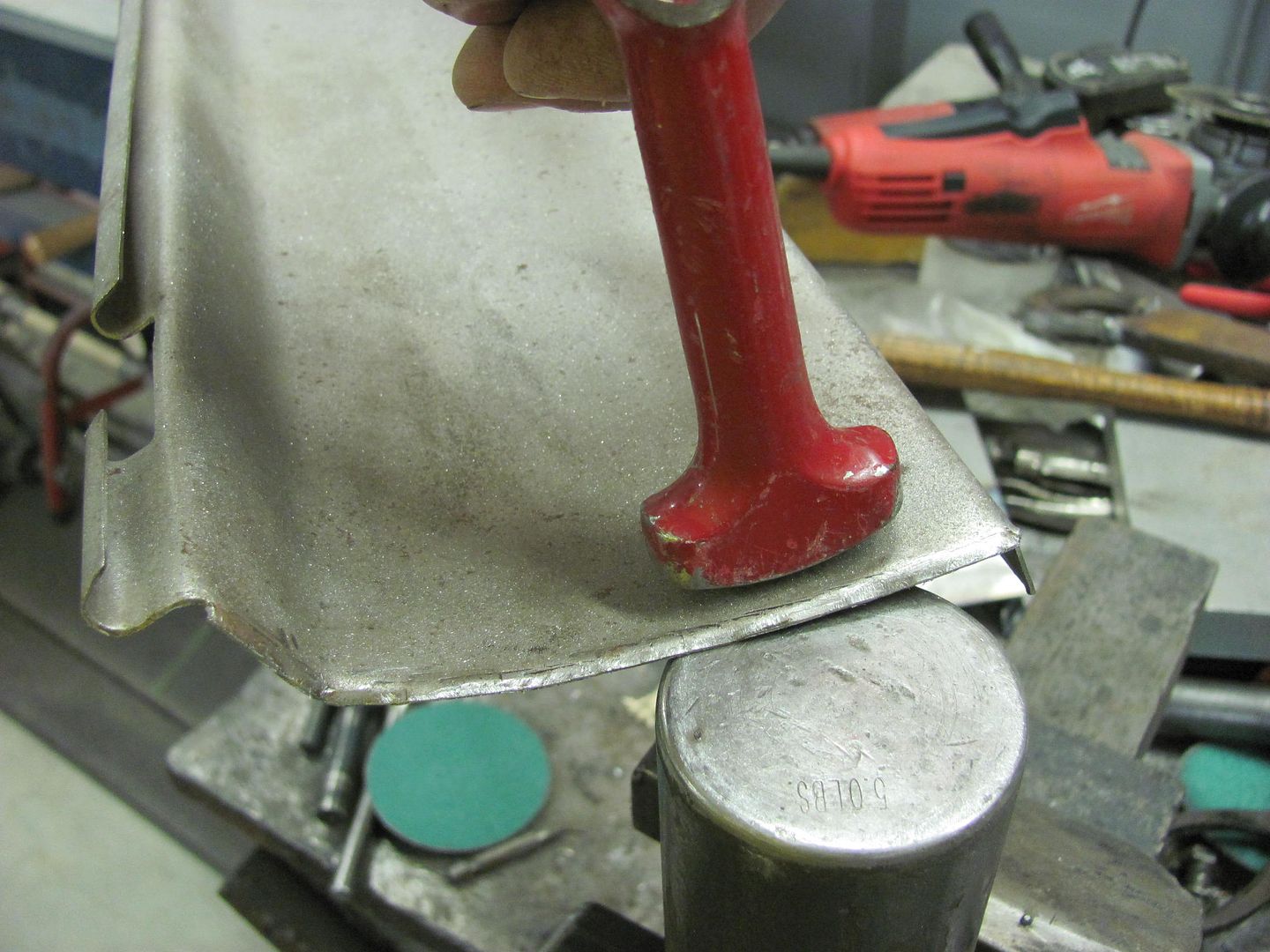
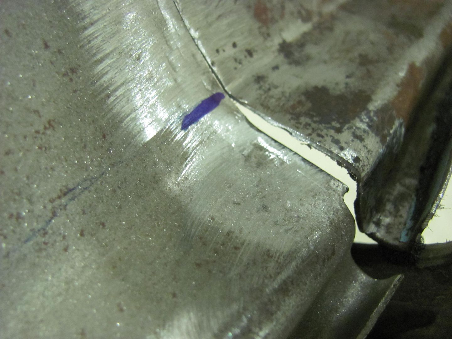
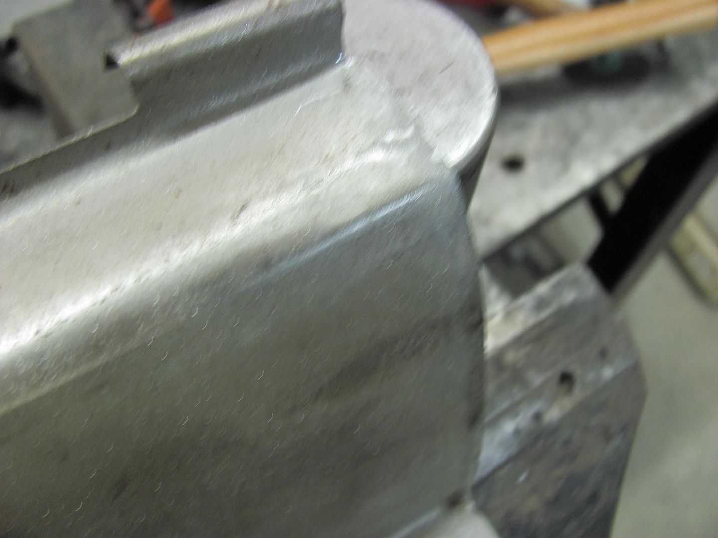
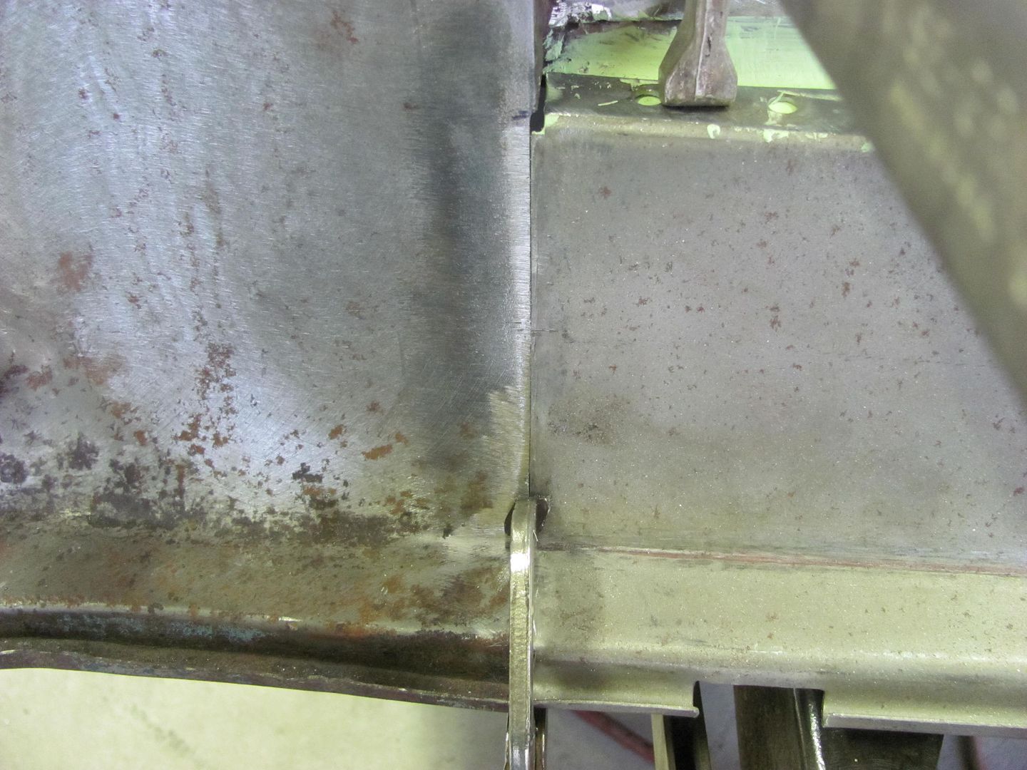
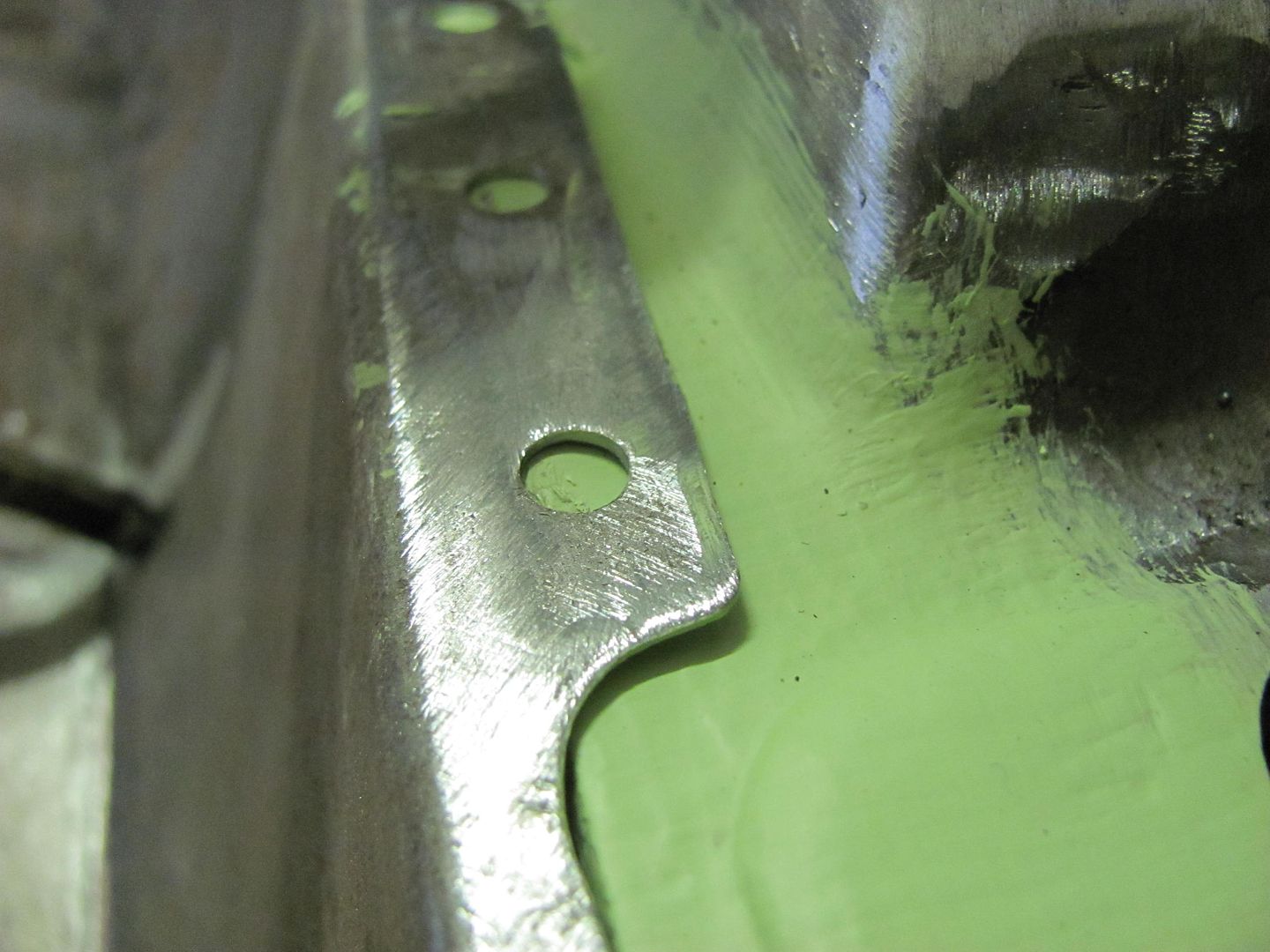
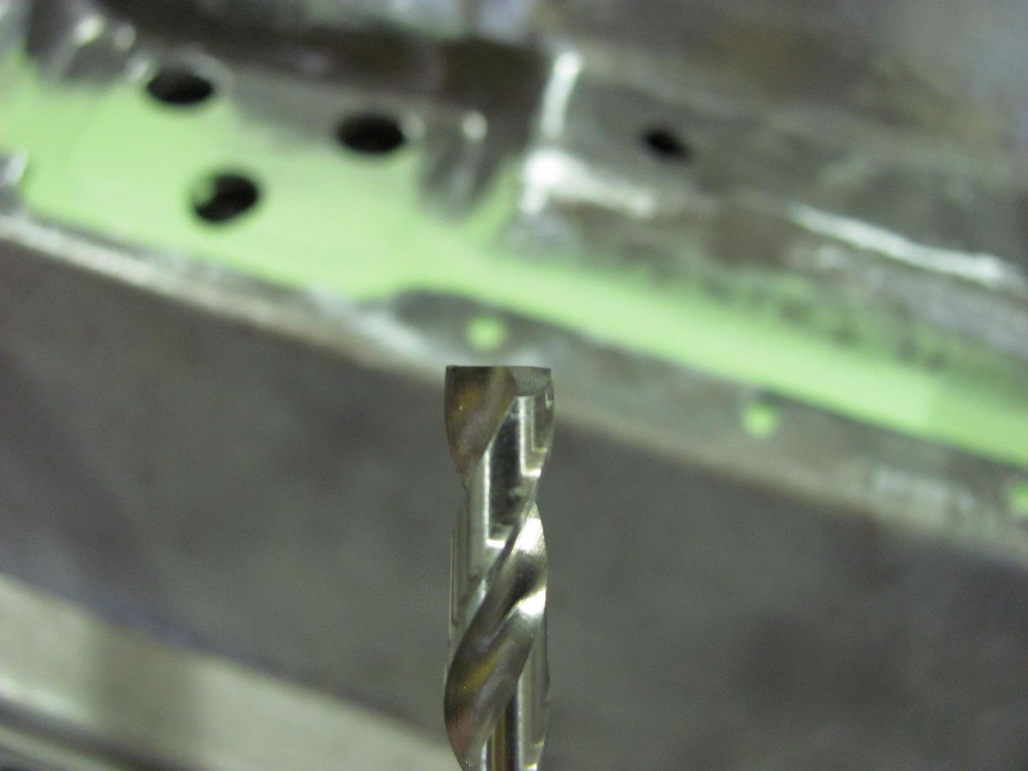
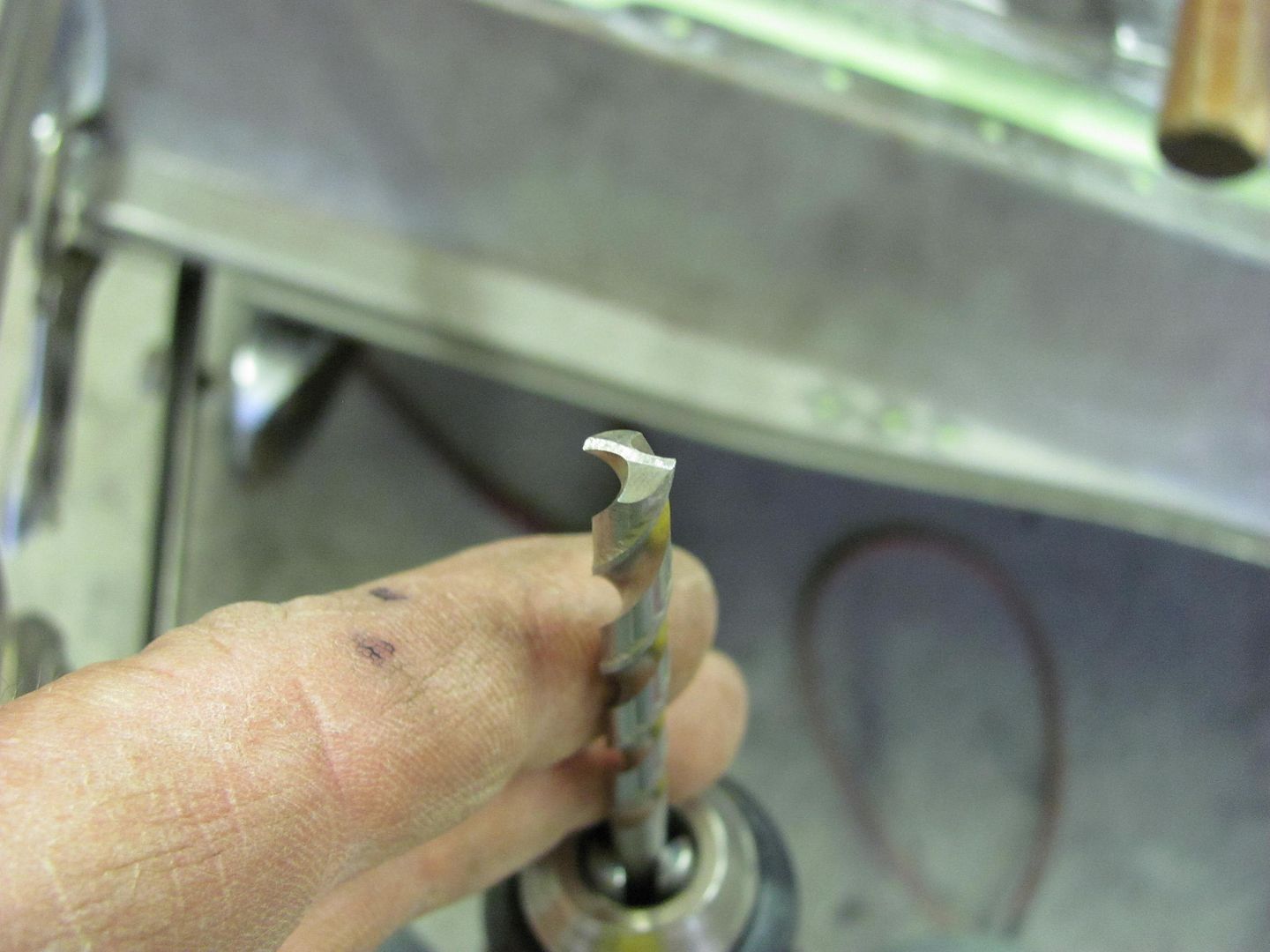
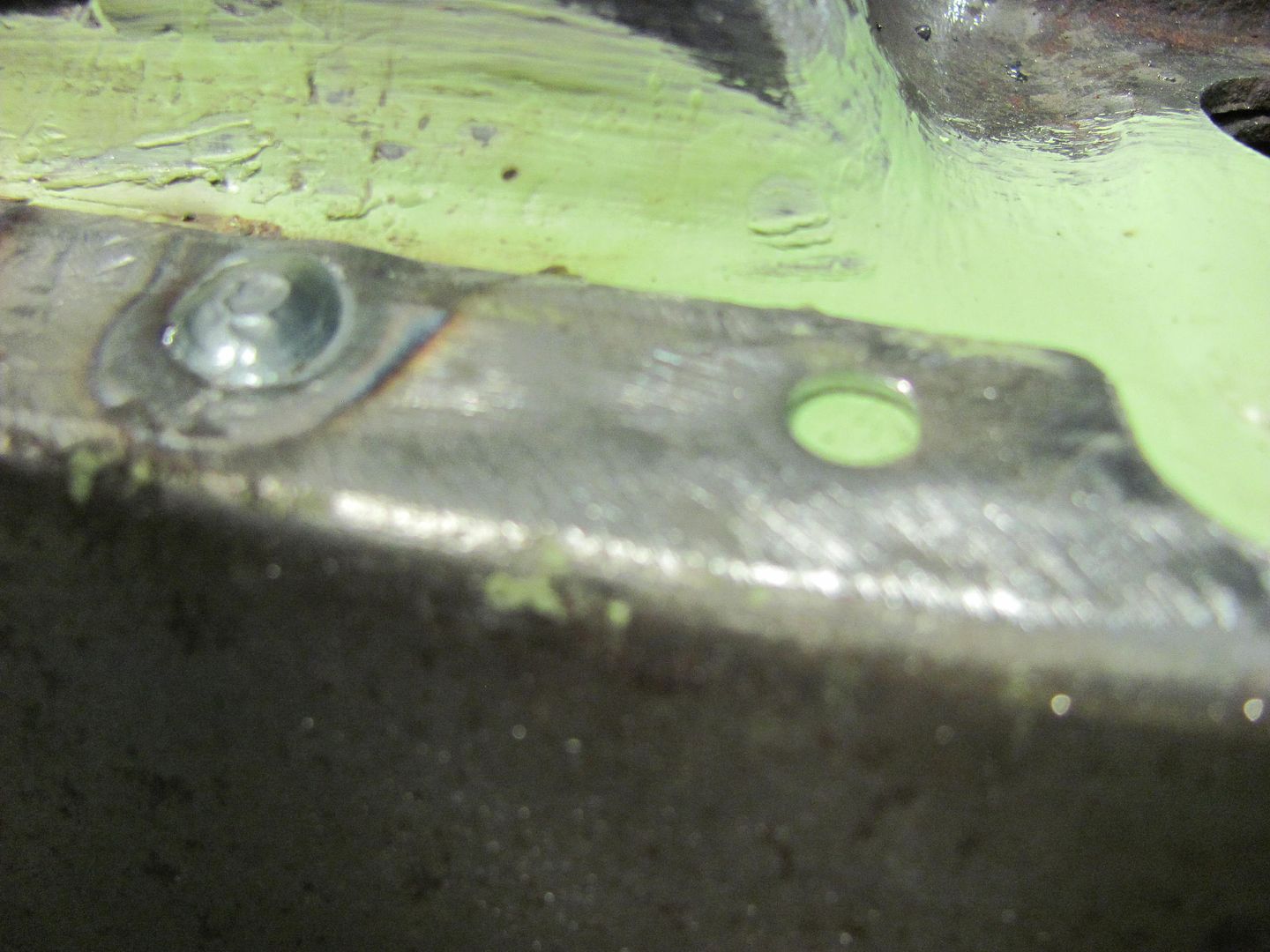
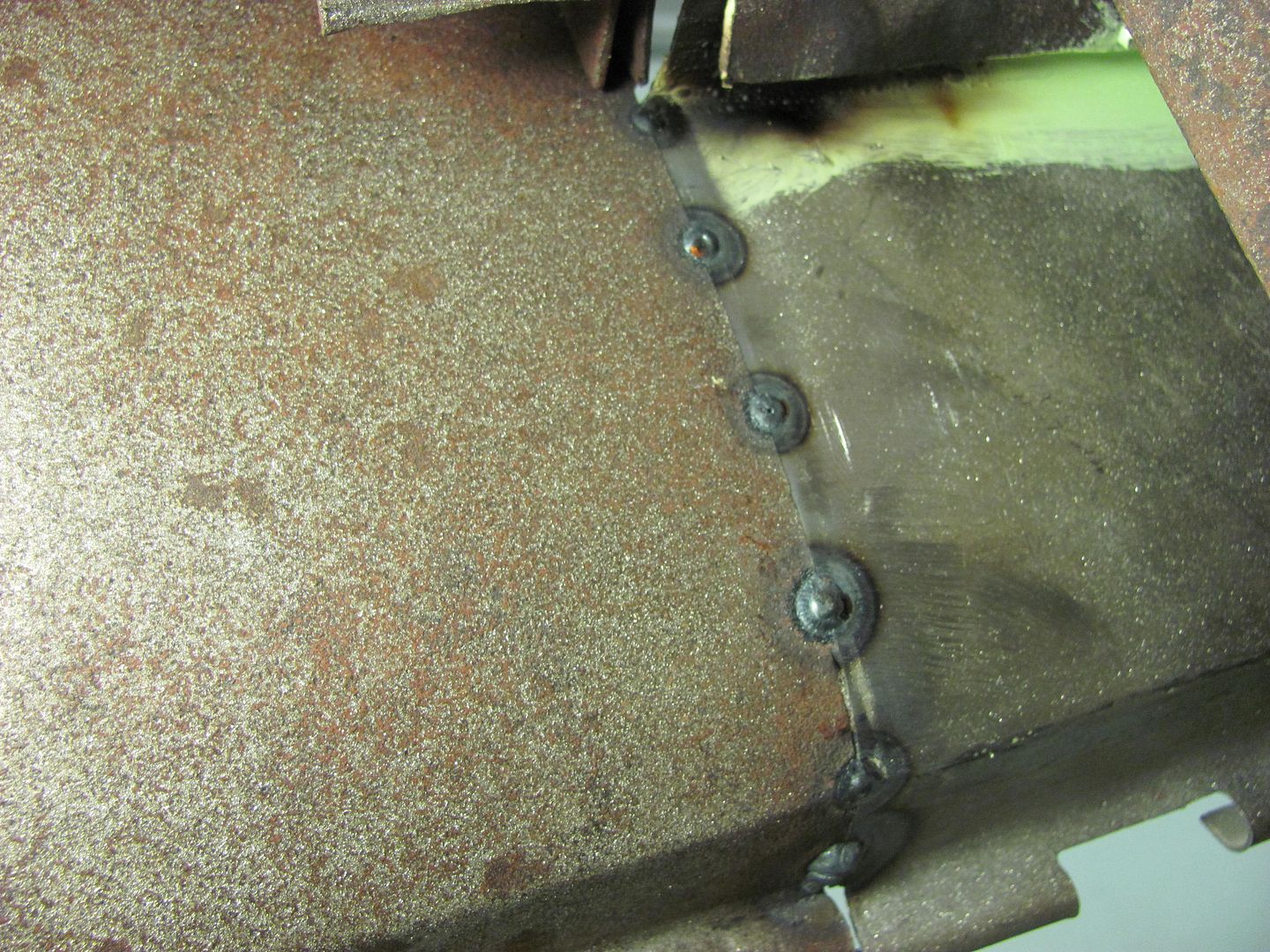
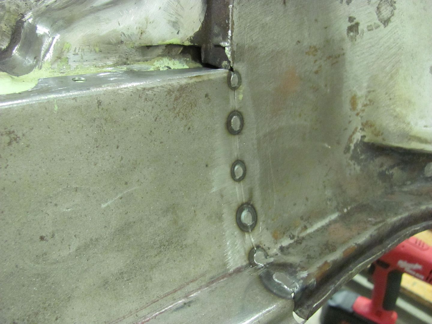
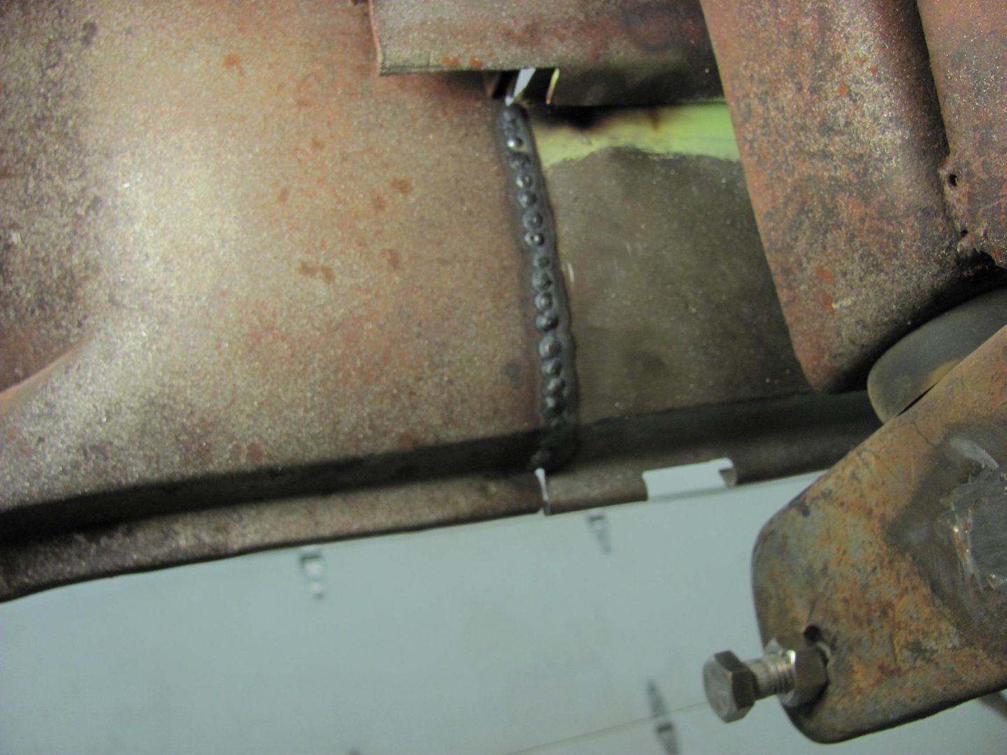
Tonight I went to my BIL's and borrowed his plasma cutter to put the new holes in the mounting flanges of the crossmember. After all that welding, drill bits do not play nicely. Holes added....


Picture017-1.jpg


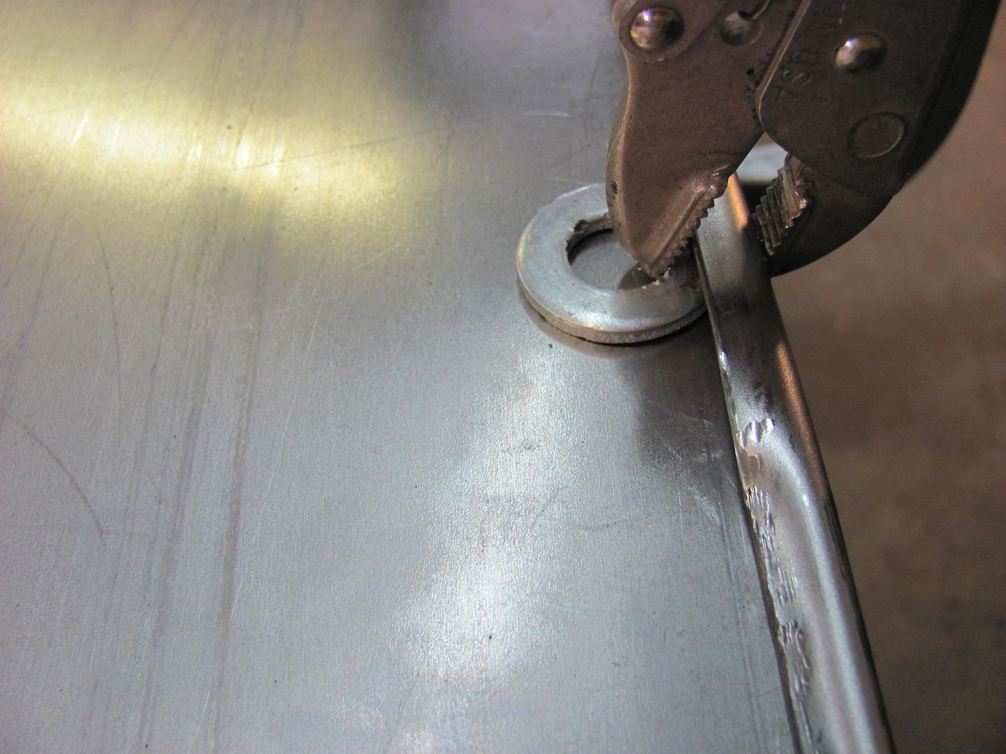
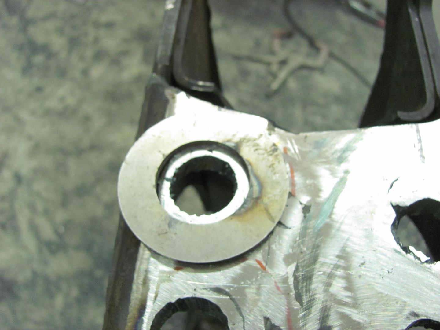
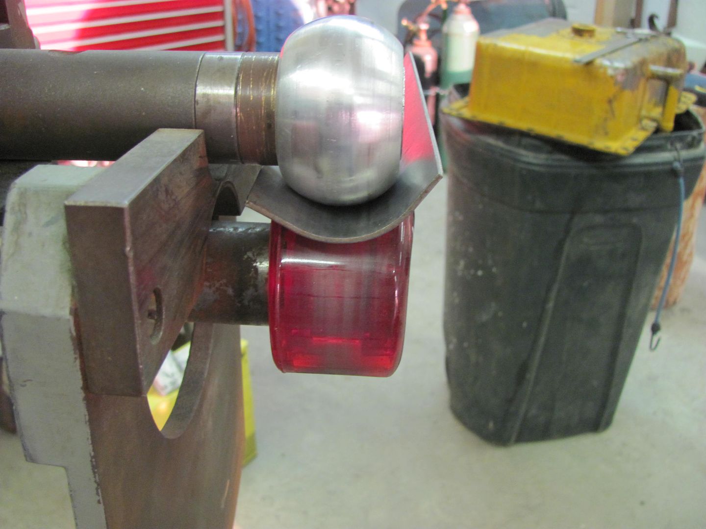
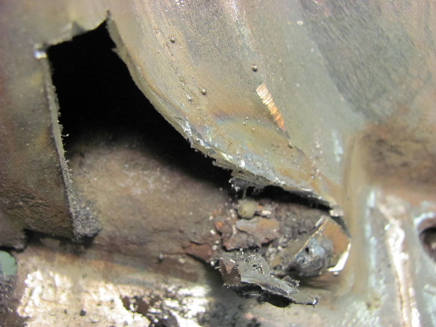
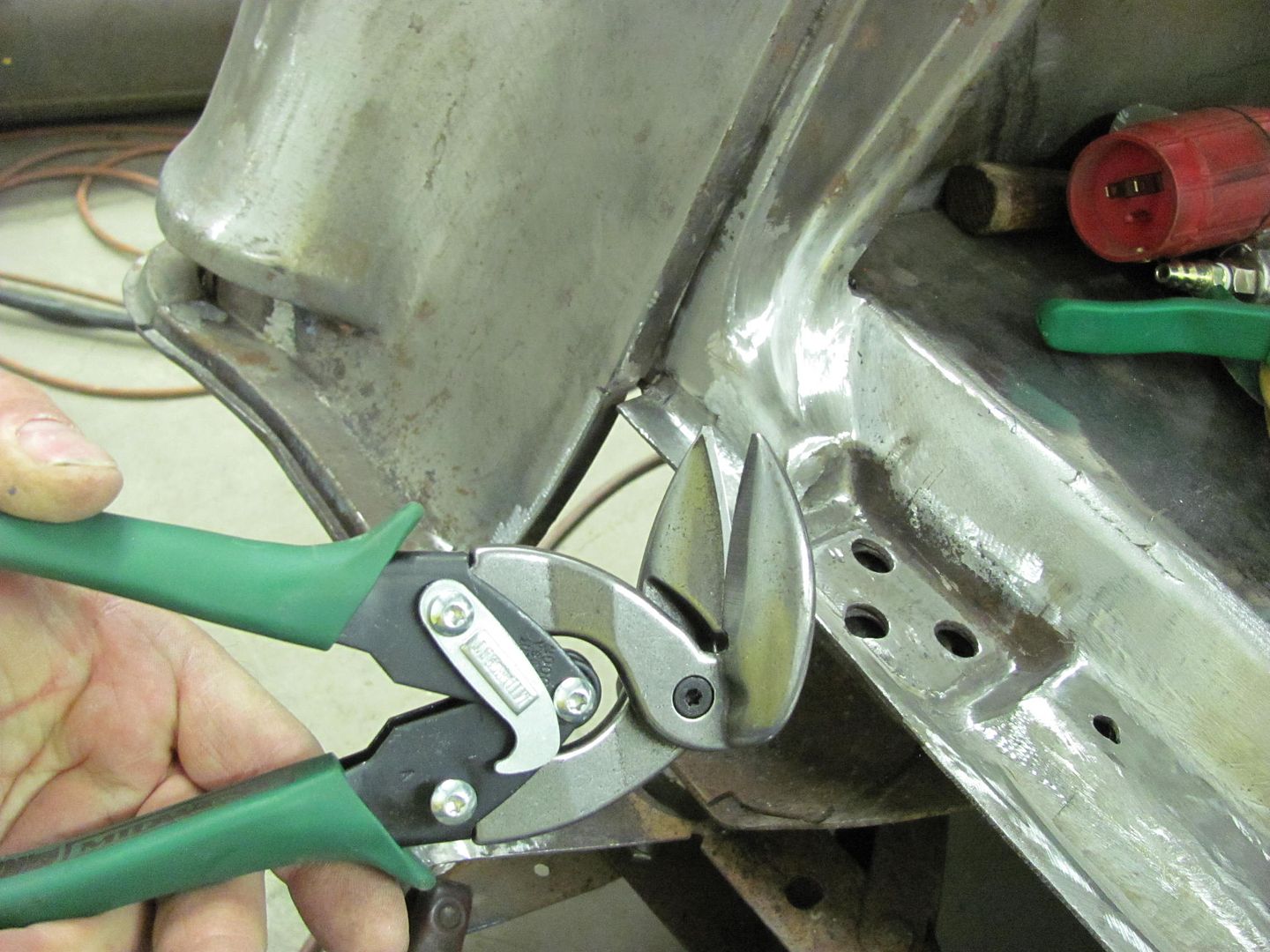
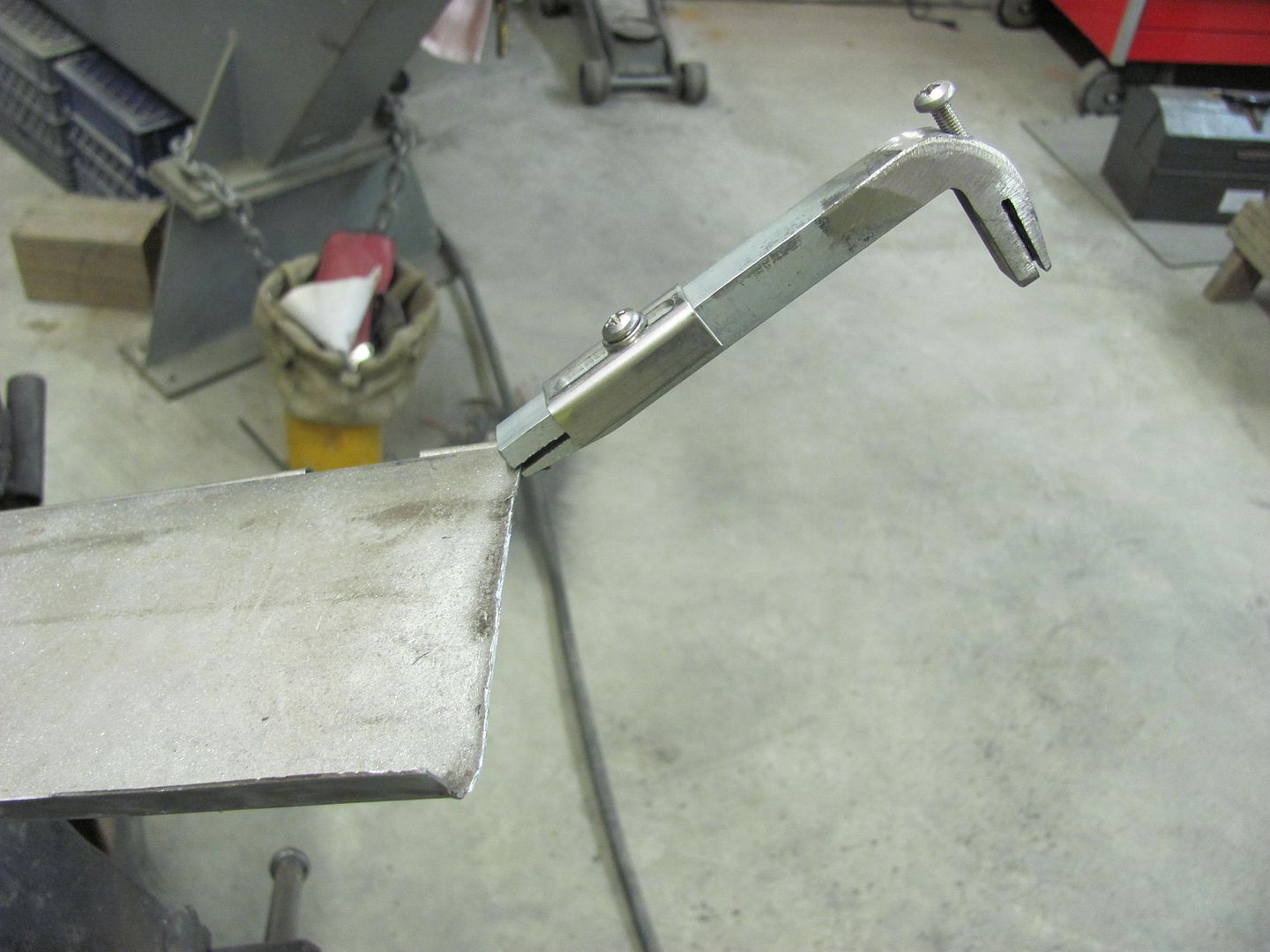
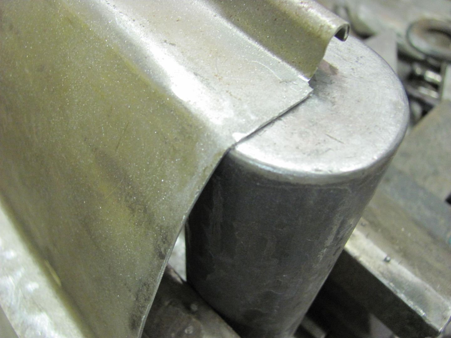
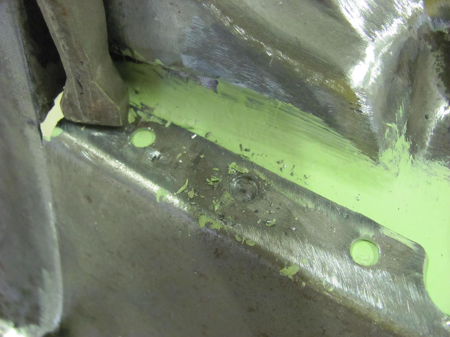
Used a washer with a 1-1/4 hole, which worked just about right as a template for the plasma torch to provide a 3/4 clearance hole....


Picture018-1.jpg


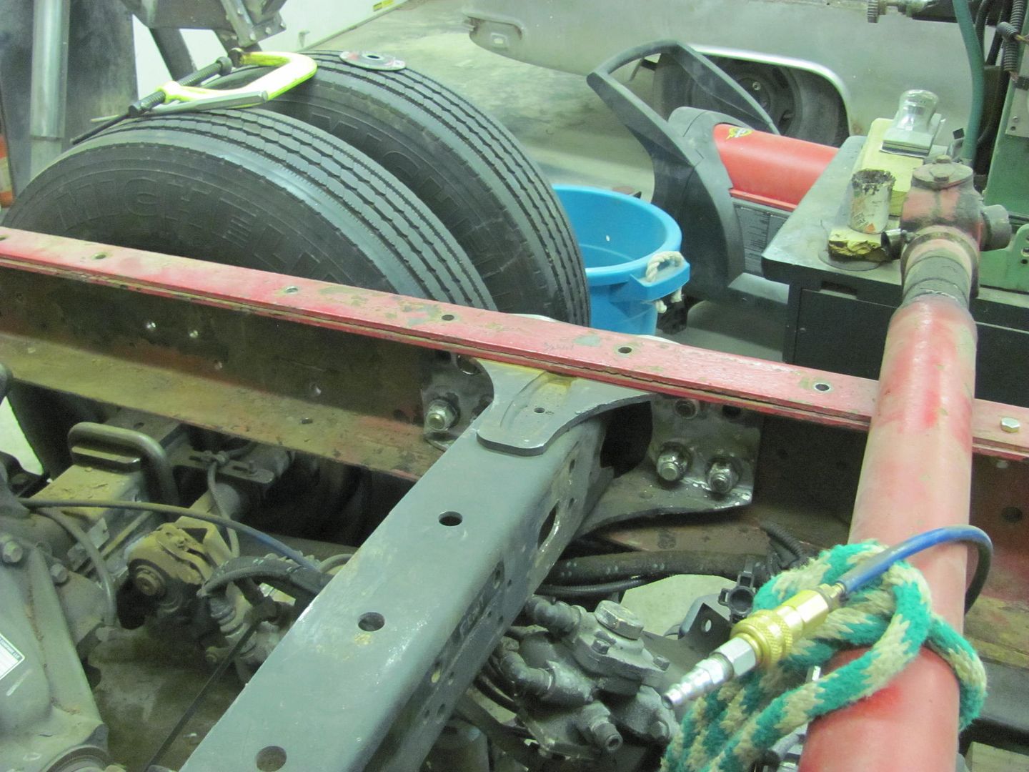
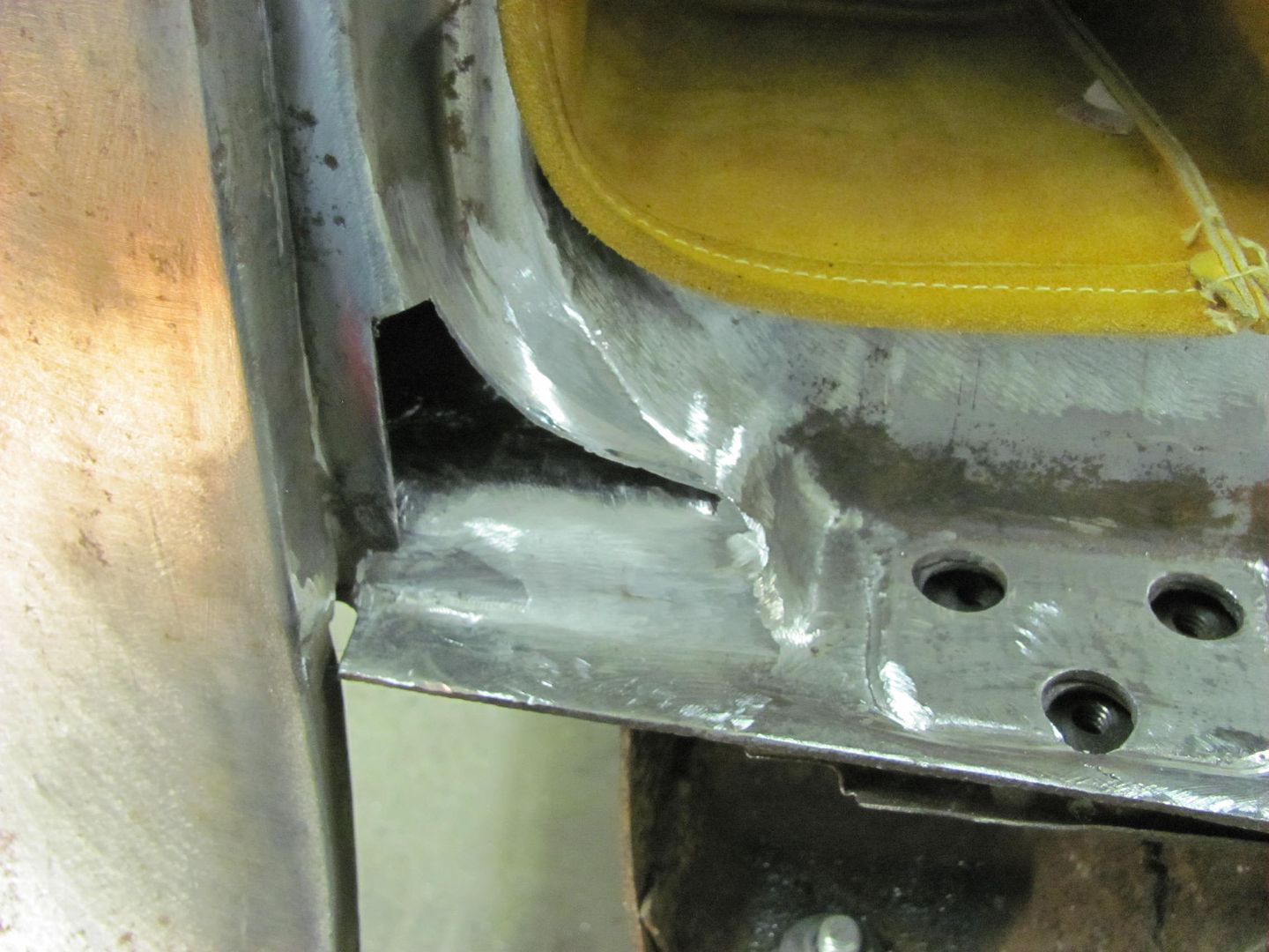
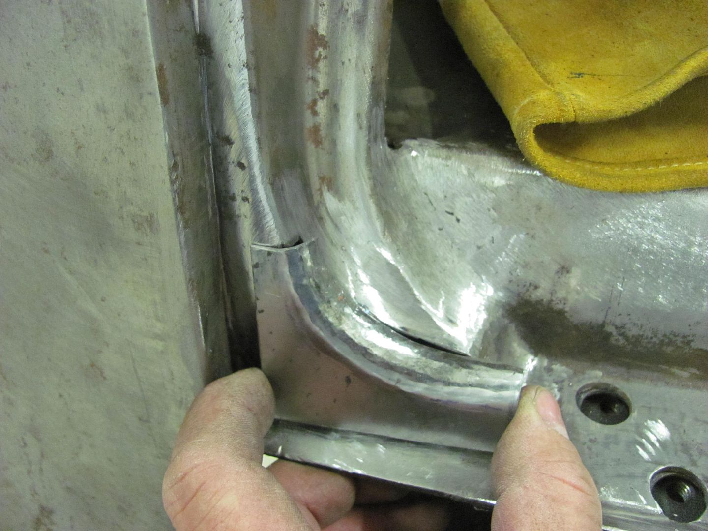
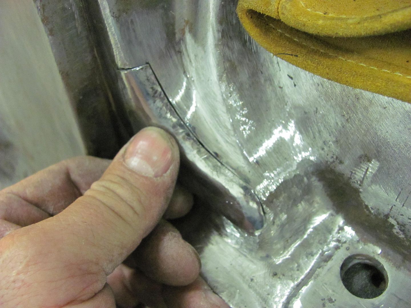
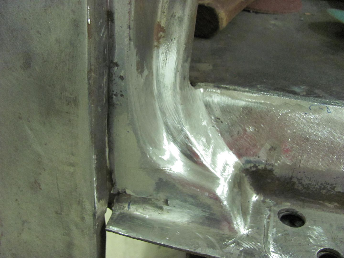
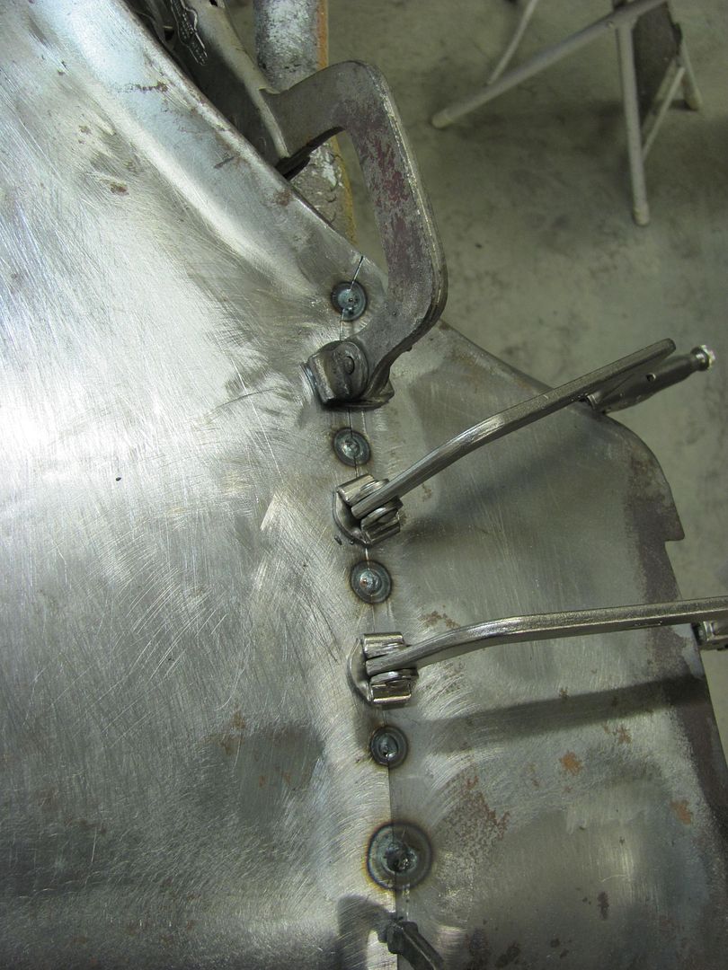
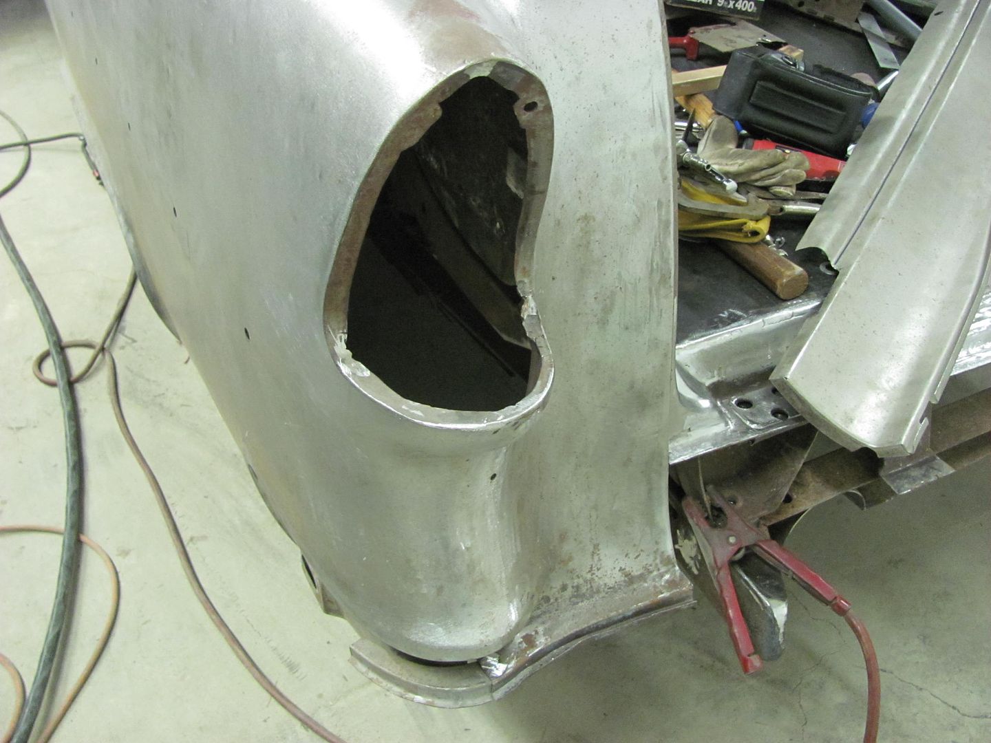
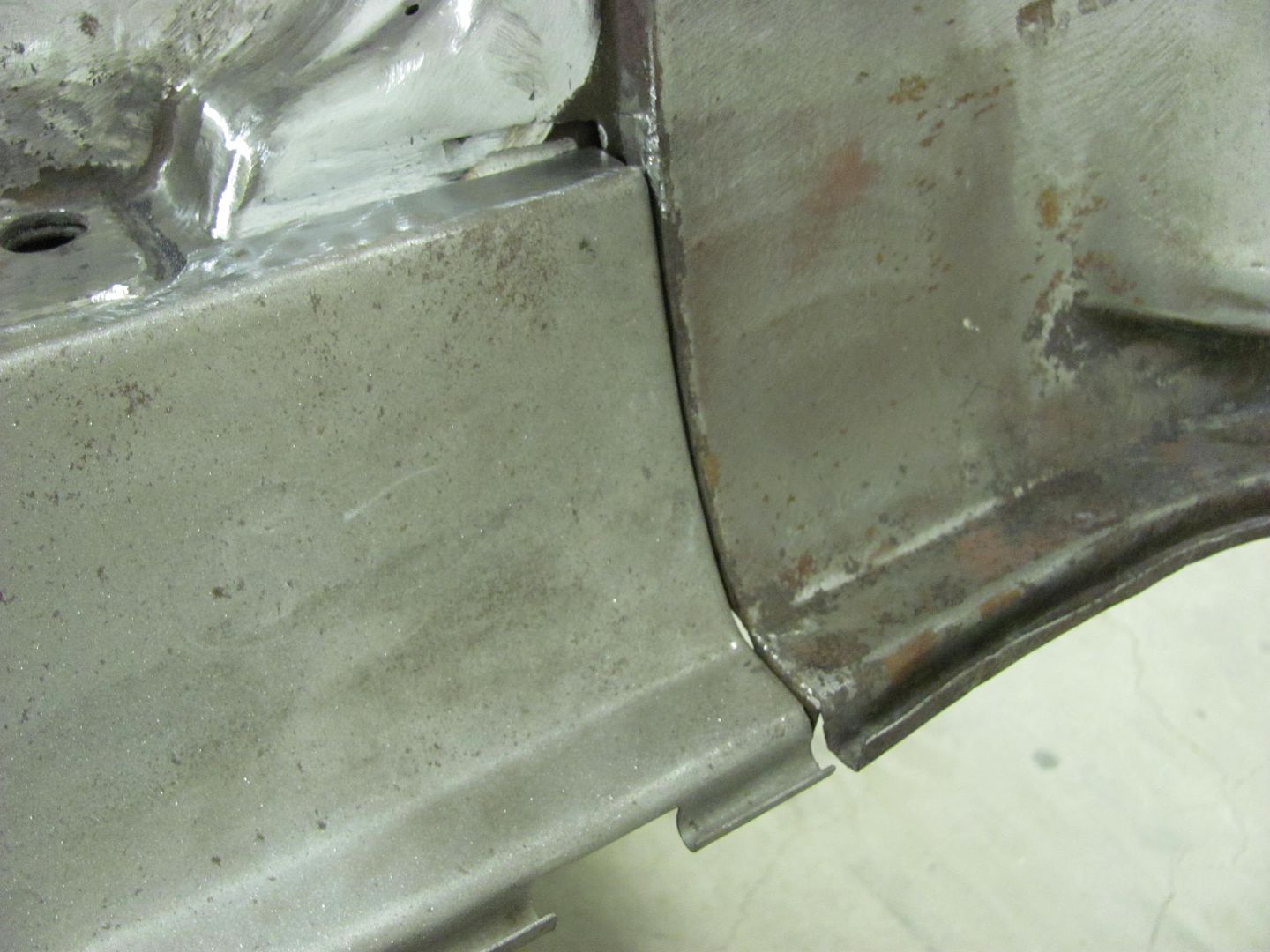
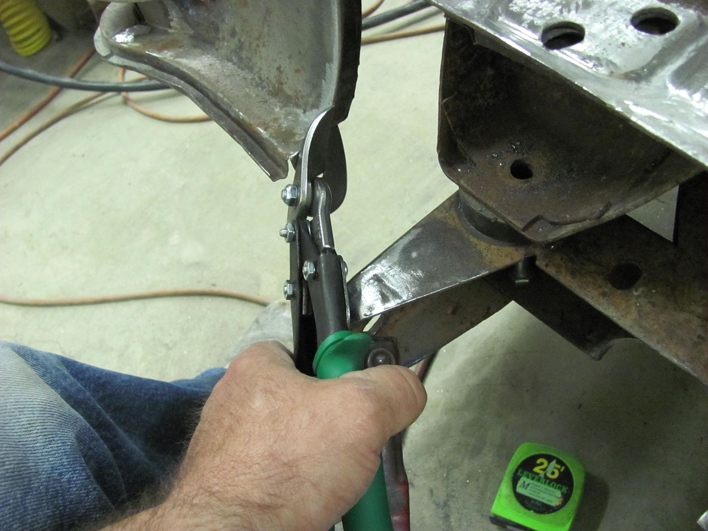
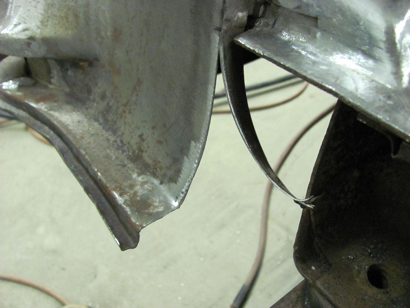
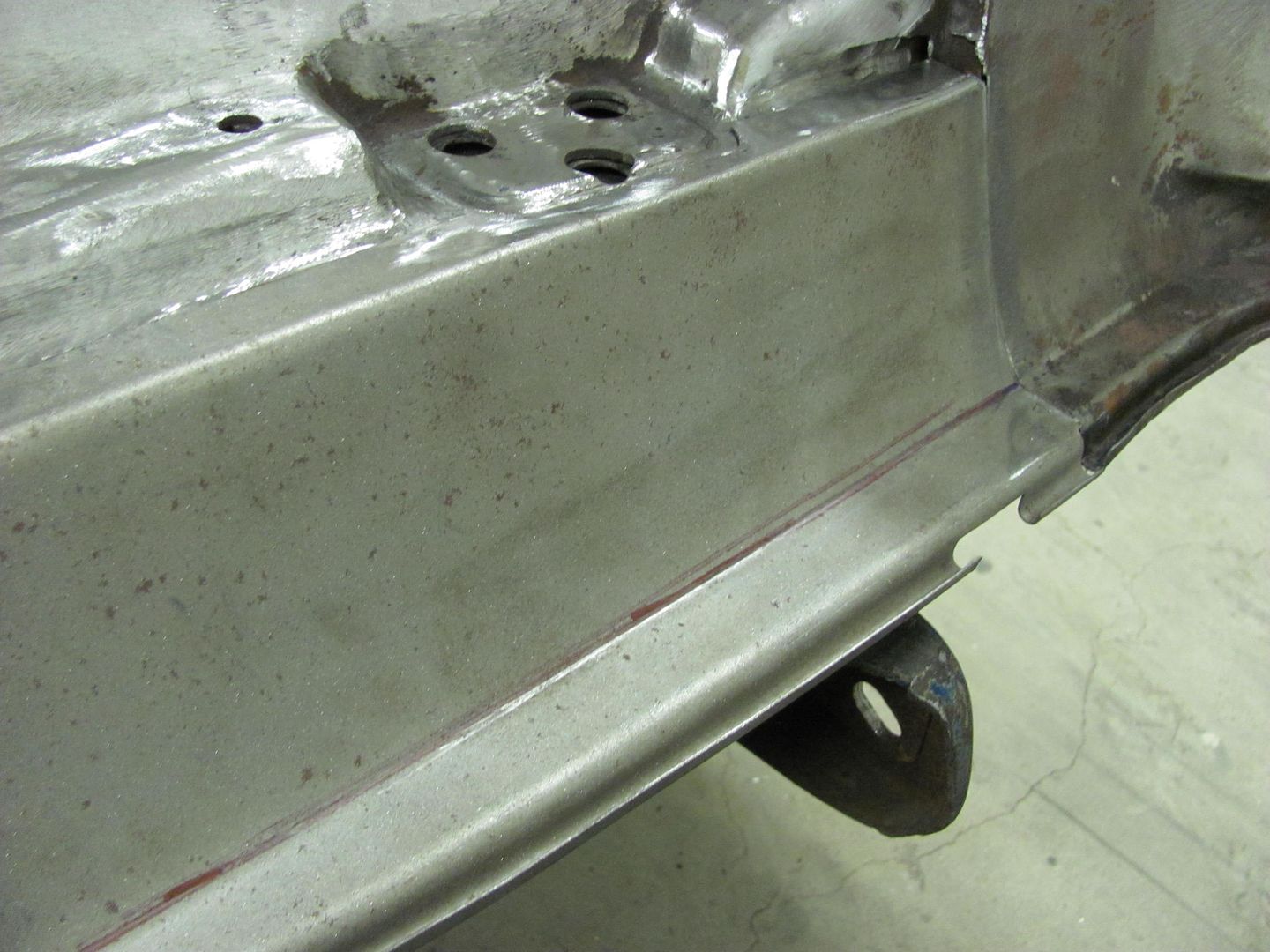
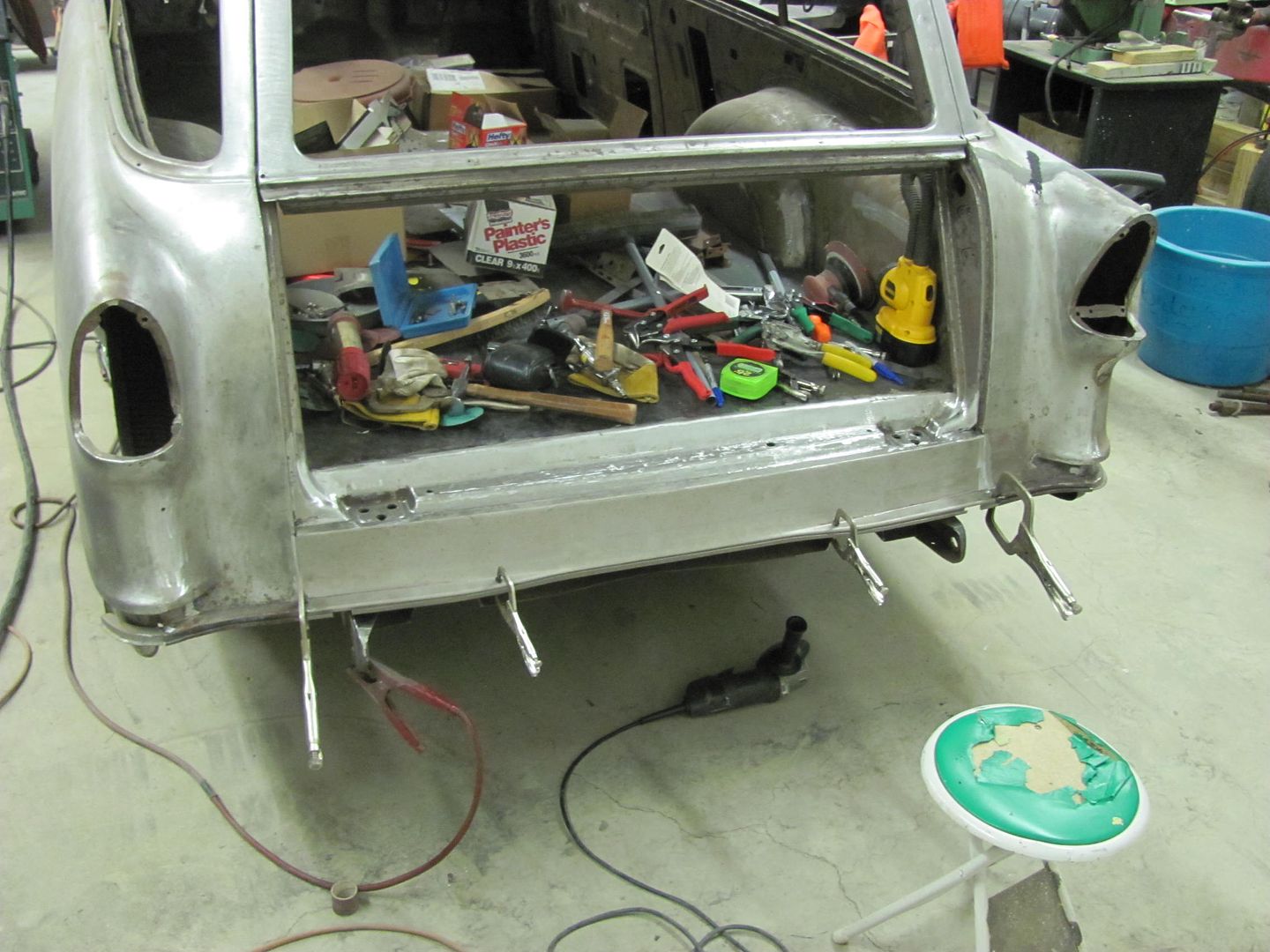
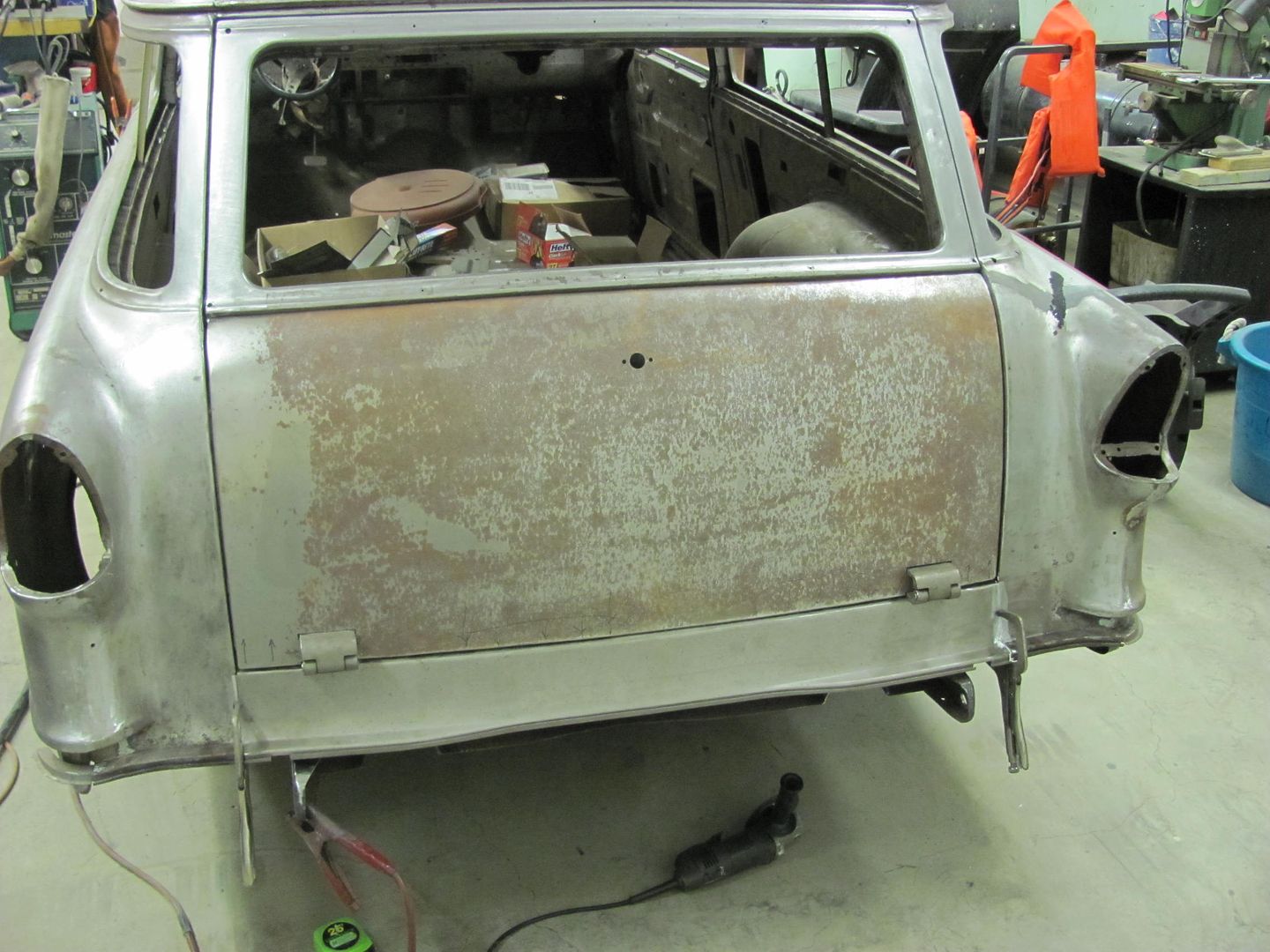
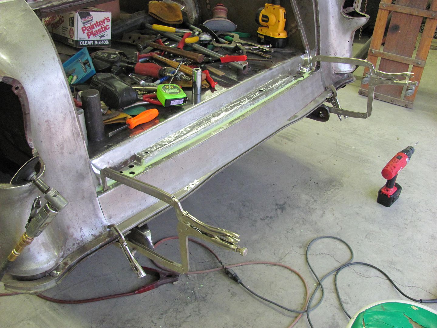
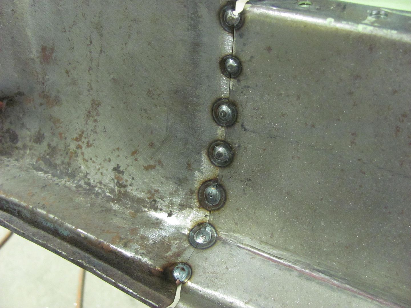
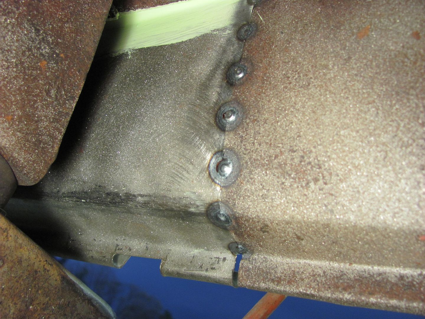
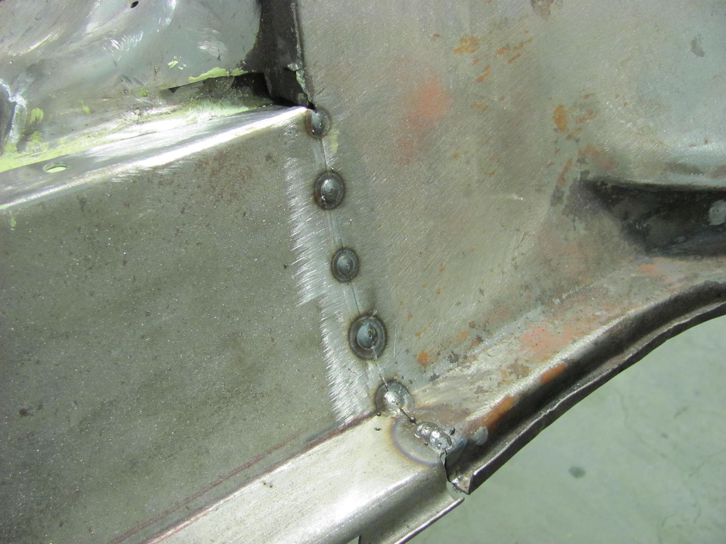
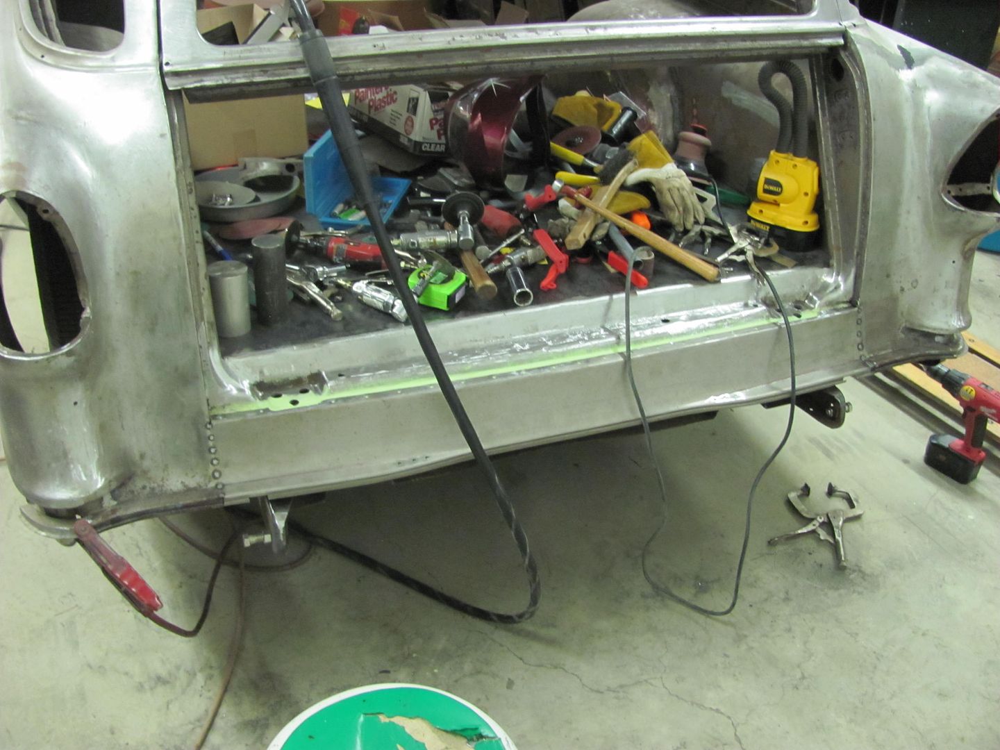
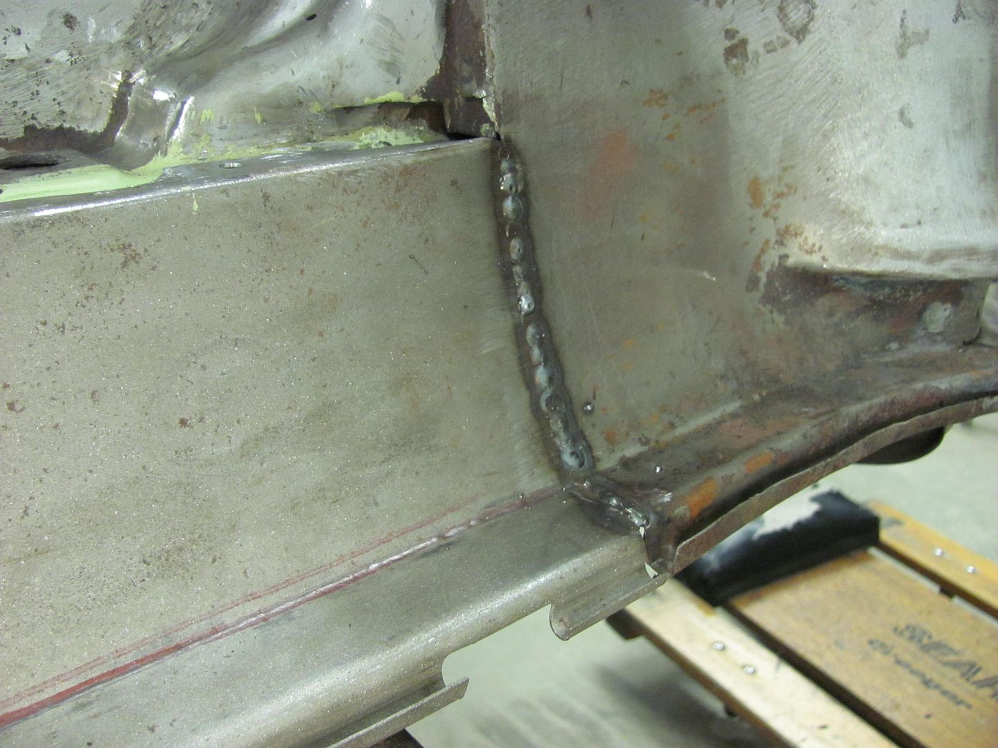
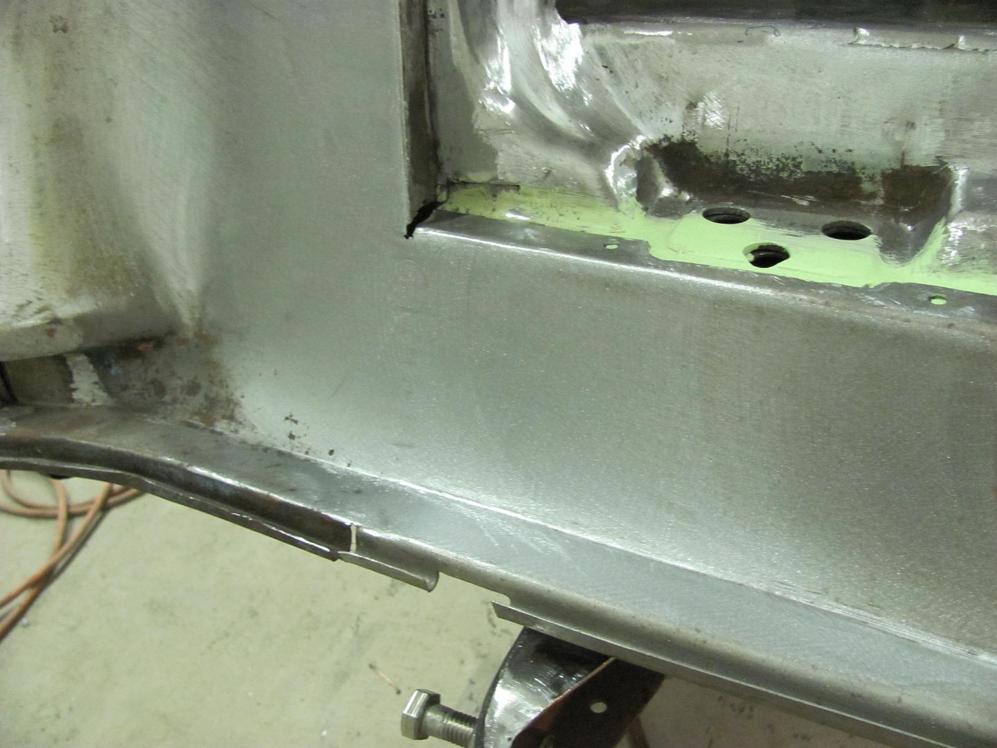
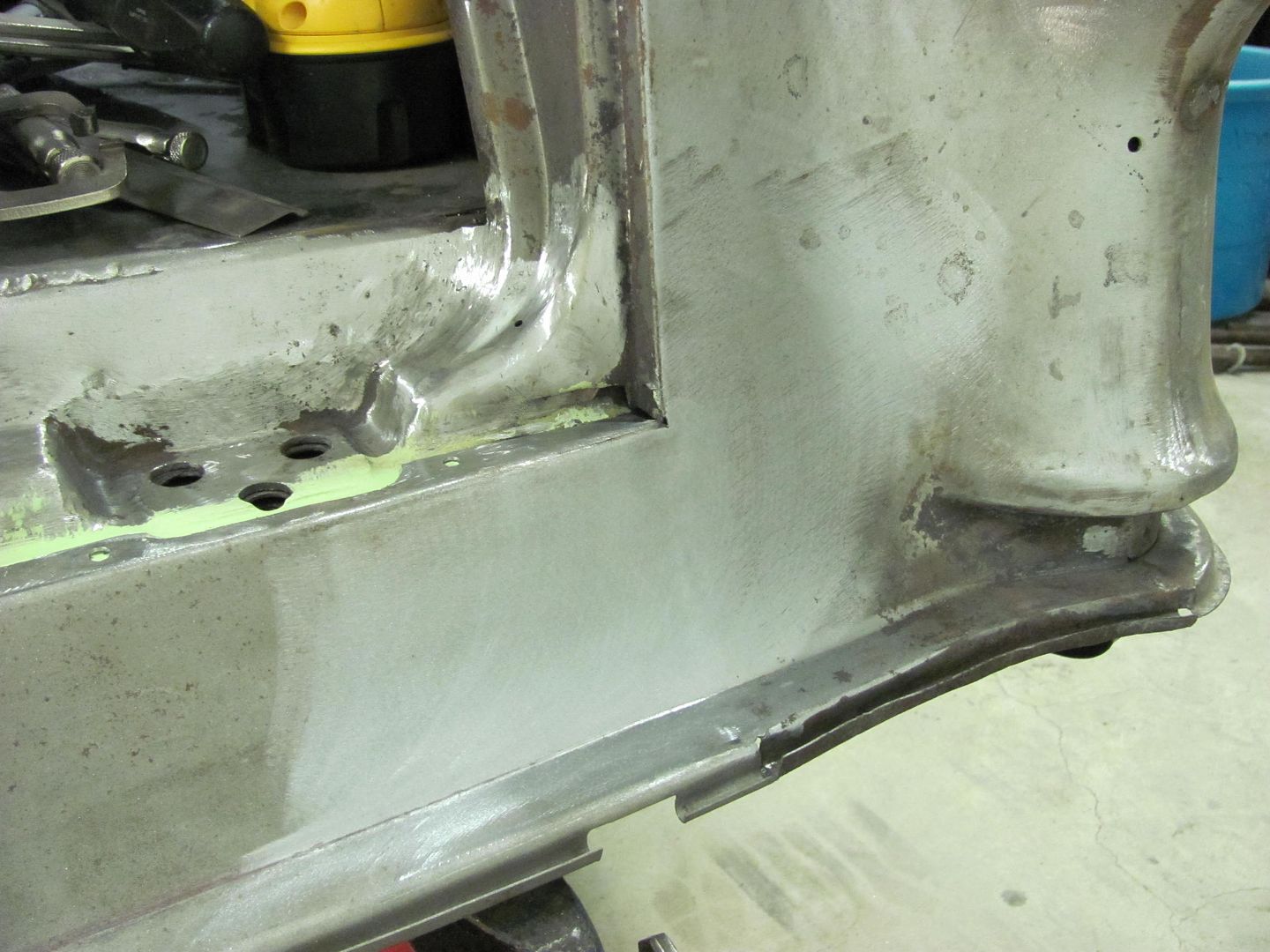
And now some progress you can actually see, the crossmember installed. Still need to lay out and drill the other passenger side.


Picture021-1.jpg


Picture022-1.jpg


Picture024-2.jpg


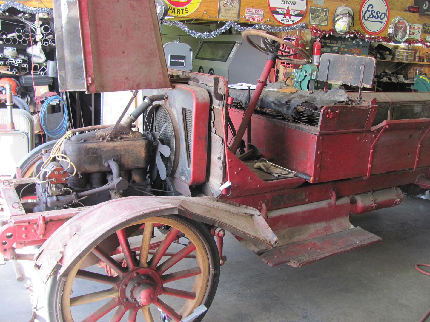
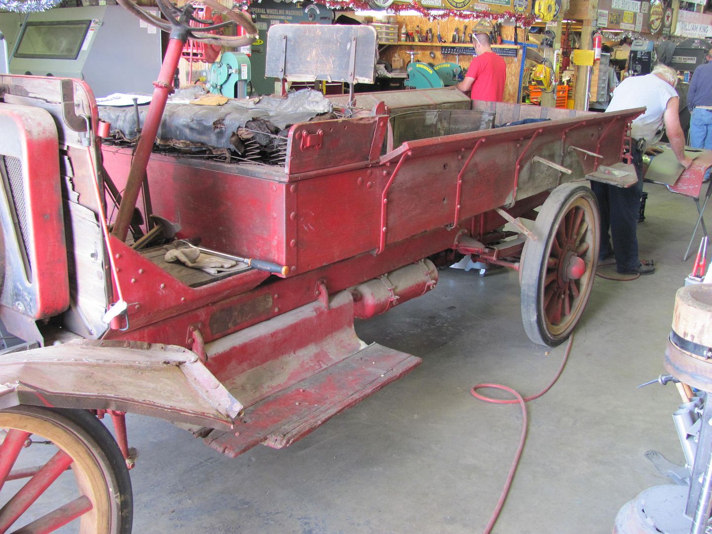
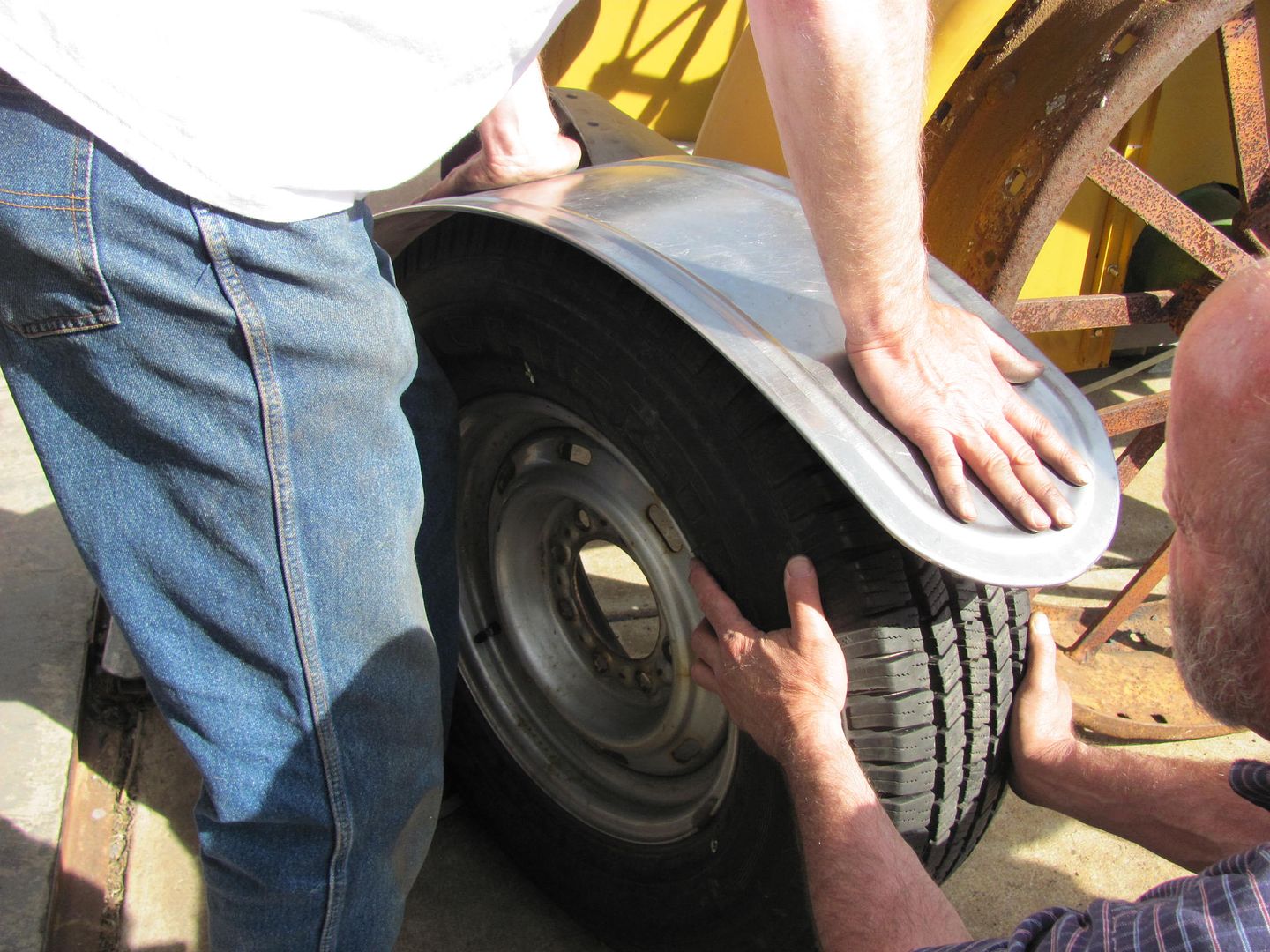
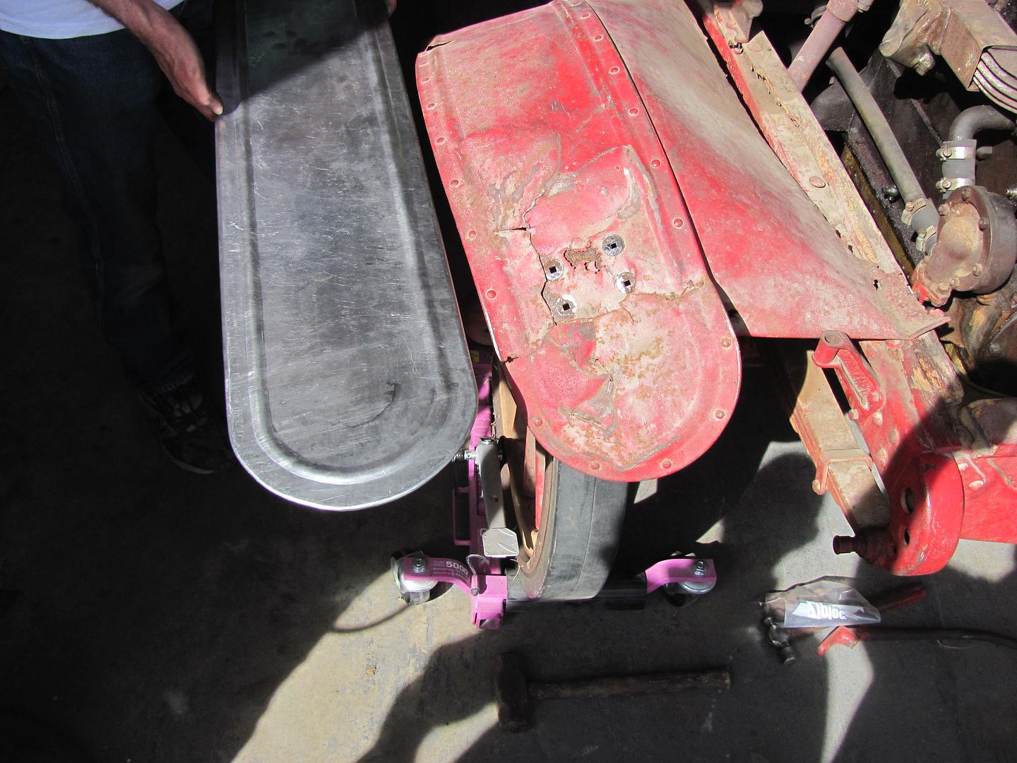
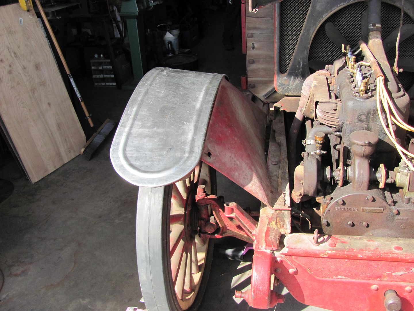
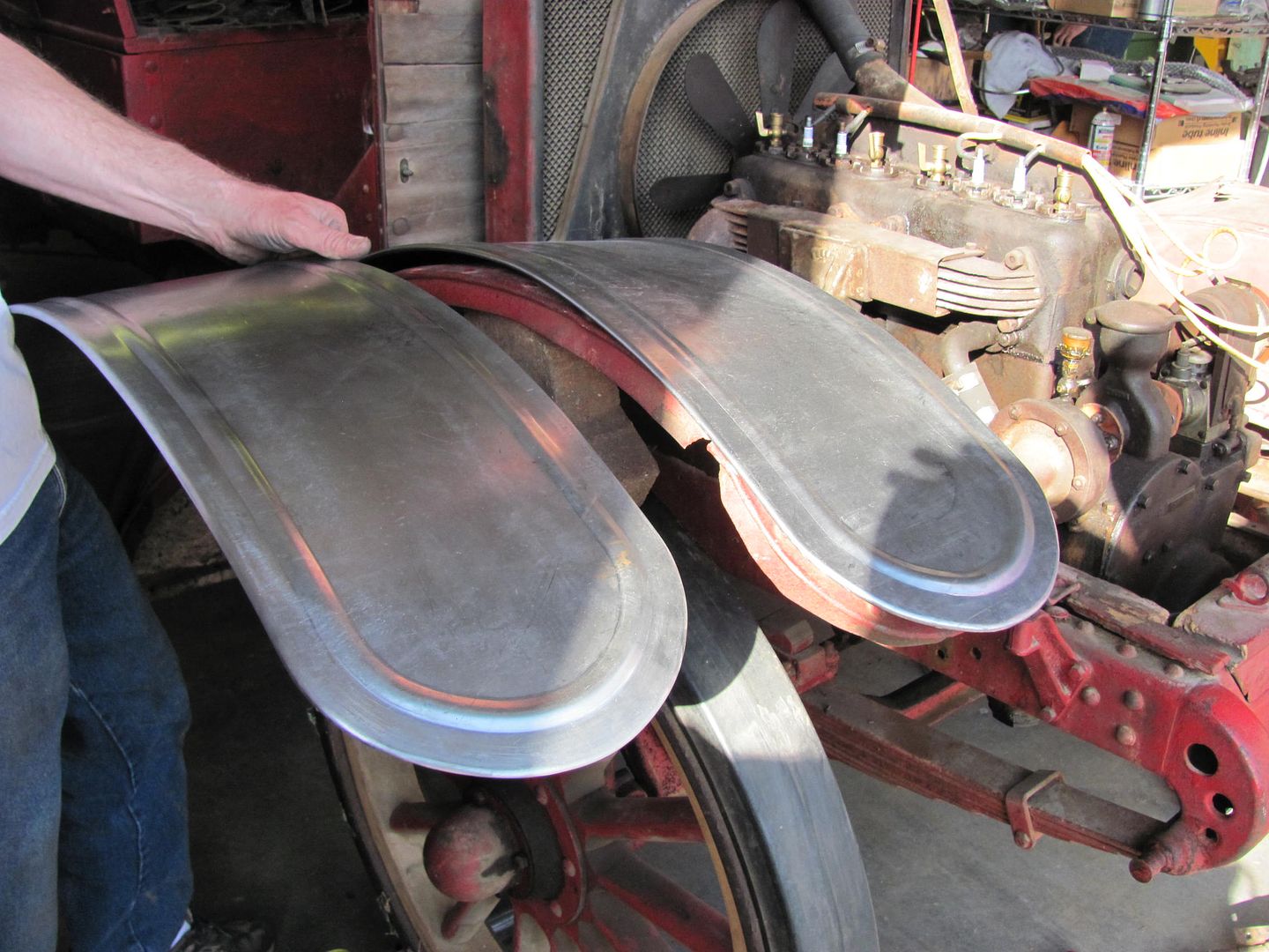
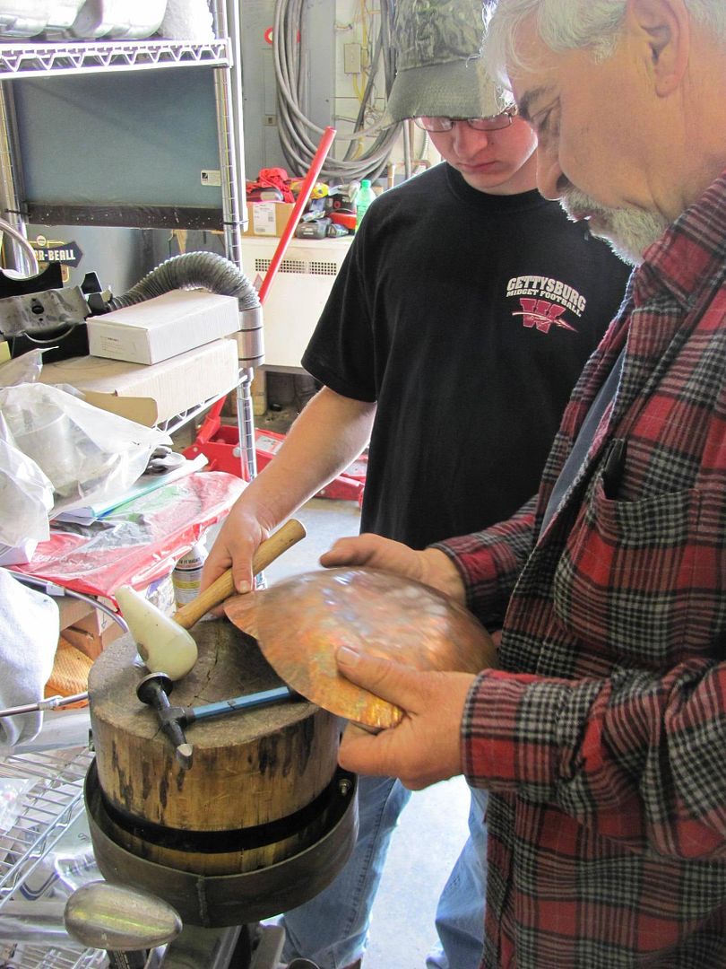
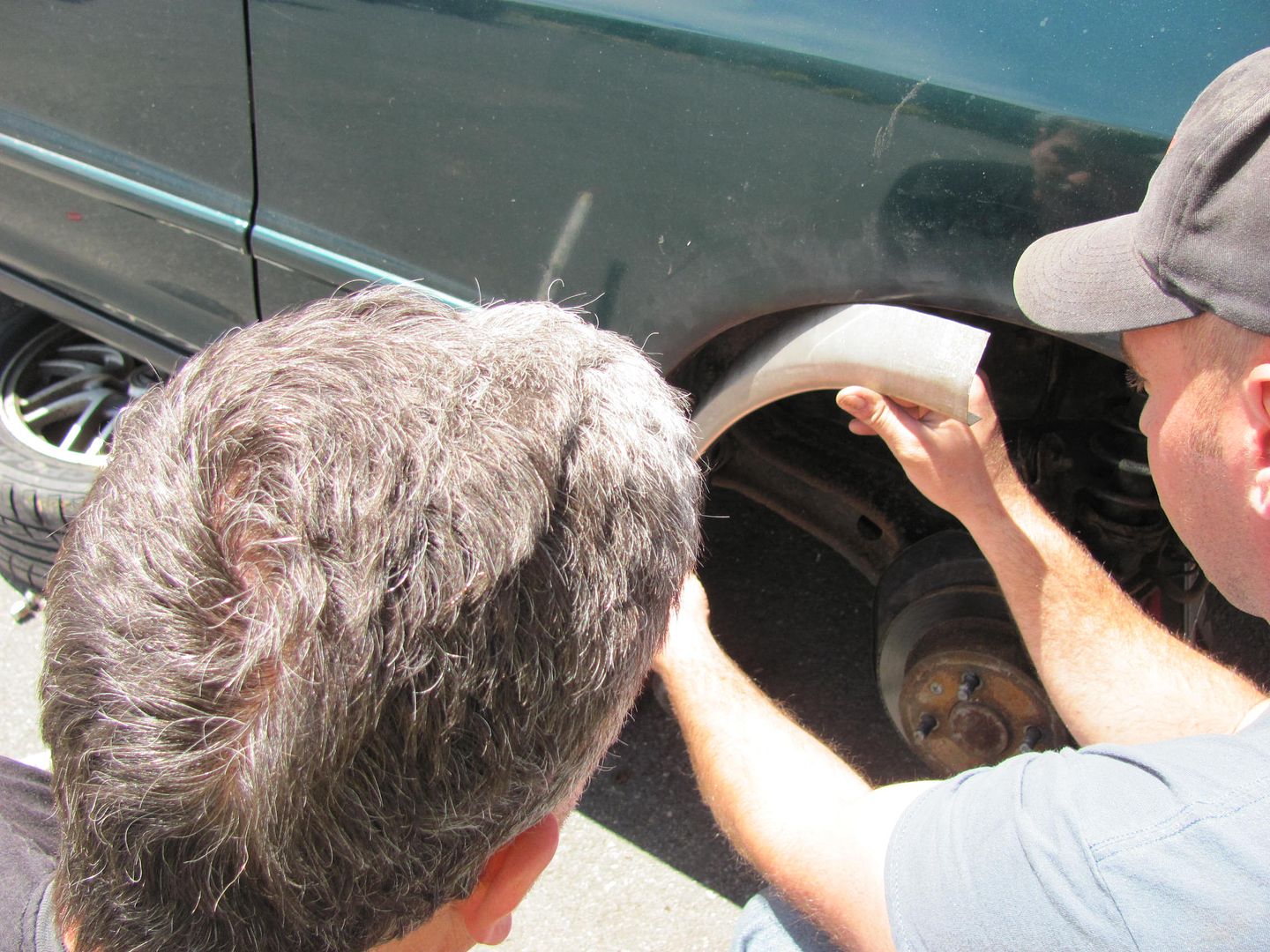
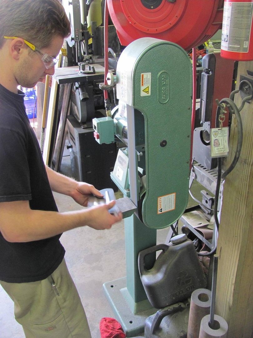
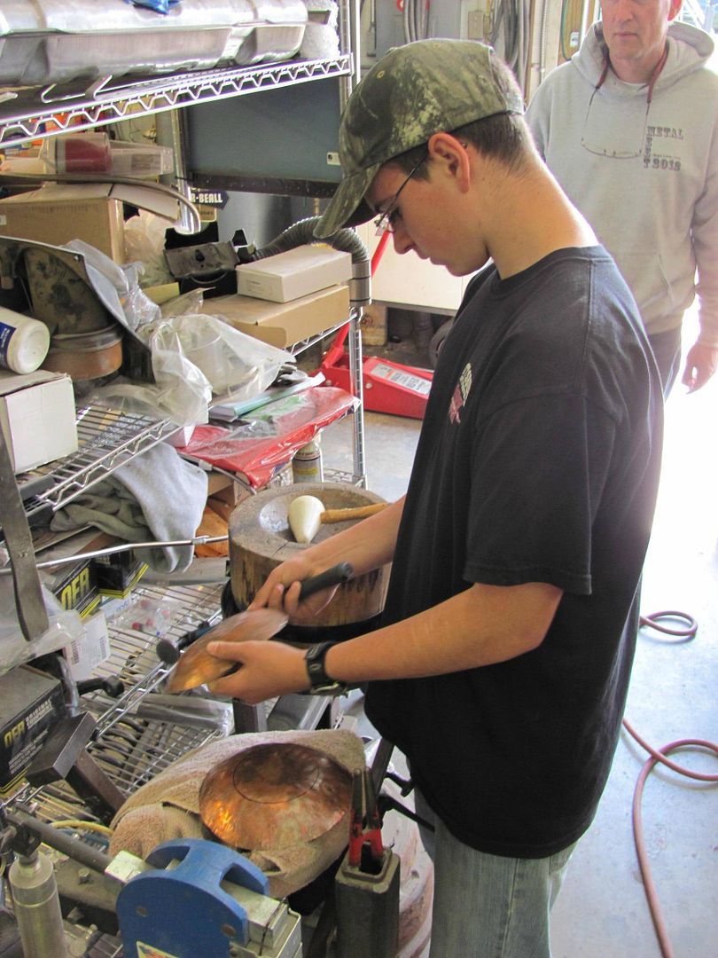
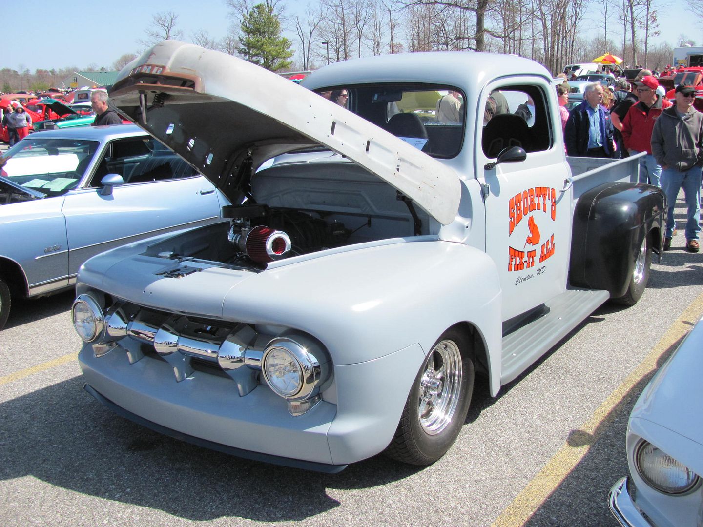
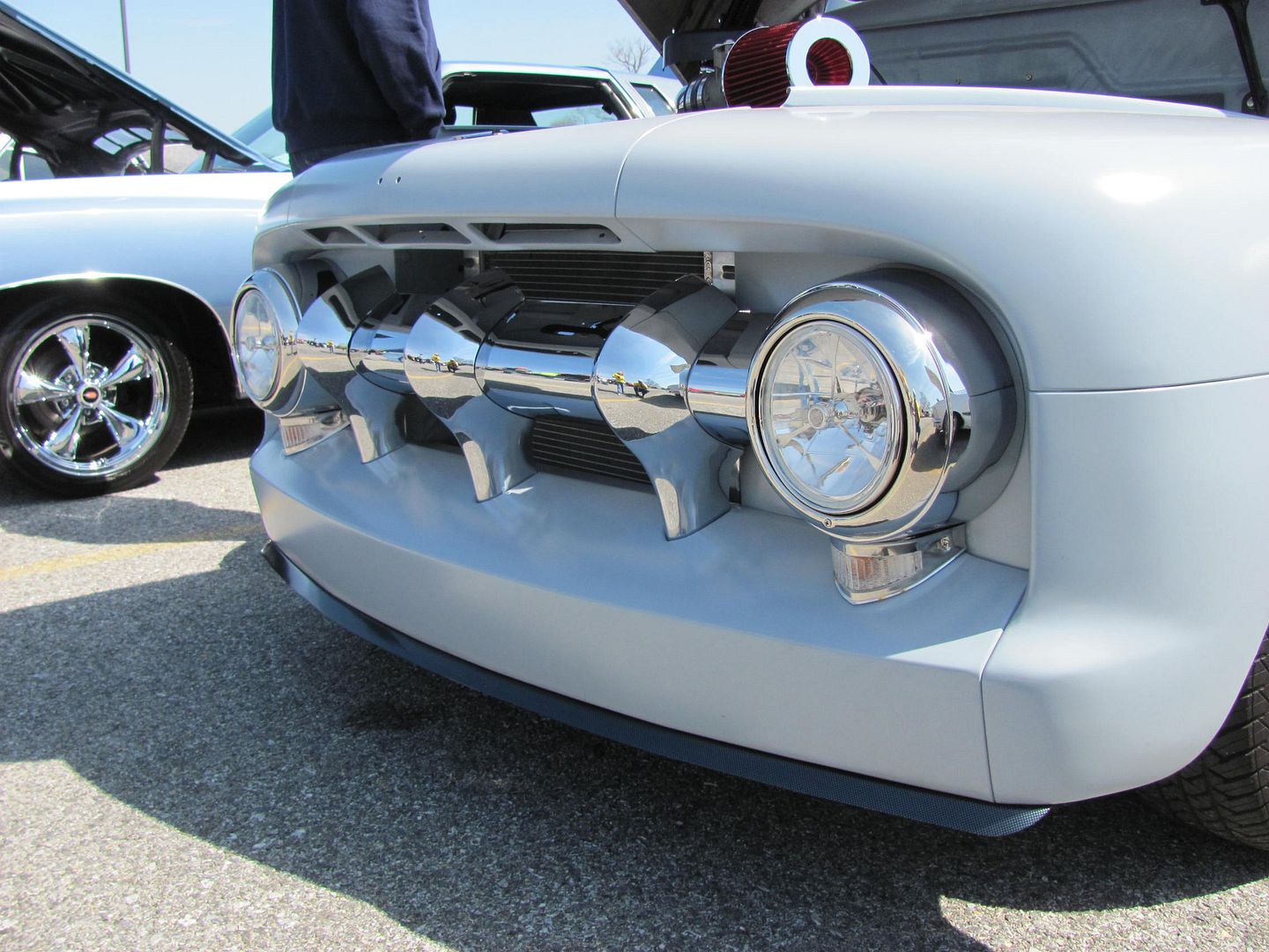
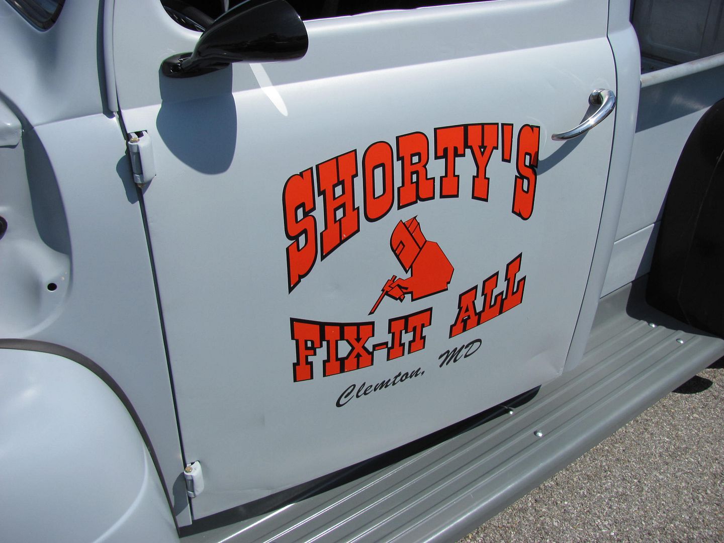
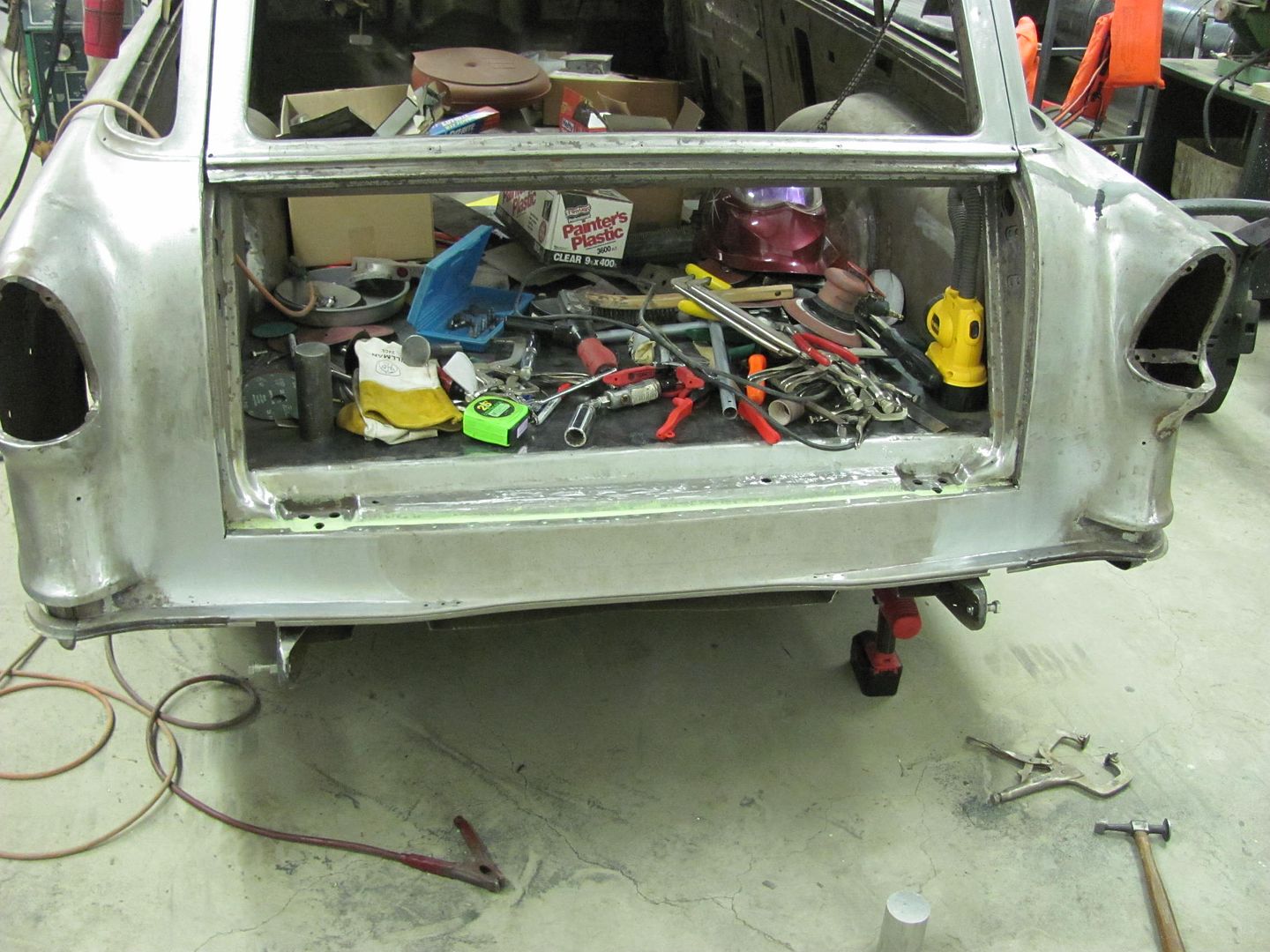
And now, just to show some eye candy, here's a truck that a high school buddy is restoring, it was his father's as we were coming up, and he inherited the truck a few years back when his father passed. He and his brothers have been working the past couple years to get it back together, and this weekend marked the start of its shake-down season...


Picture002.jpg


Picture003.jpg


Picture004.jpg


Picture005.jpg
 
To avoid these ads, REGISTER NOW!

Mrcamaro

Well-known member
Joined
Feb 26, 2013
Messages
101
Location
Las Vegas
Great work as always. Was supposed to start my Camaro build thread but that is on the backburner for now since it's nice enough already and can hold off before the paint goes bad over the rust so I picked up a 69' Chevy Stepside http://www.garagejournal.com/forum/showthread.php?t=195769
and doing a full frame off so that is my project for now and looking forward to using some of the techniques I learned from reading your posts.
 
Last edited:

Mrcamaro

Well-known member
Joined
Feb 26, 2013
Messages
101
Location
Las Vegas
Picture239.jpg


How did you get this shape? On this picture it looks like you are more to one side. You didn't make it by having the two wheels dead center of the piece? Or did you roll it with them more to once side til the other angle is more perpendicular to the wheels and the other half of the piece? Wondering because I have to make a similar piece for the truck door and a fender.
 
OP
M

MP&C

Well-known member
Joined
Oct 21, 2009
Messages
4,396
Location
Leonardtown, MD
If you look at that picture a bit closer you can see the "track marks" from the upper wheel to show the paths that were taken, and I just kept repeating, applying more pressure to the adjustment screw until it got to the shape you see...


attachment.php
 

Attachments

  • Picture239a.jpg
    Picture239a.jpg
    37 KB · Views: 2,970
OP
M

MP&C

Well-known member
Joined
Oct 21, 2009
Messages
4,396
Location
Leonardtown, MD
Had a couple hours this evening so I decided to remove some mud daubers nest....


Picture251.jpg


Picture252.jpg


Picture254.jpg


Used a combination of burr grinder, roloc sander, etc, to clean out the rust and scale as best I could. Once the car is up on the rotisserie again, the troublesome voids such as these will get a good flood of paint.


Picture256.jpg


As this one needs a bit more flange turned in, the inside will need a bit more stretch to go with it. A suitable hammer with more heft will come in handy.


Picture258.jpg


Picture259.jpg


Picture260.jpg


A couple fitments and adjustments, and this is ready for the welder...


Picture261.jpg


Picture262.jpg


Picture263.jpg


Picture264.jpg


and with it getting late, we'll cover the welding on the next update..
 

BJ42LX

Well-known member
Joined
Dec 29, 2010
Messages
2,811
Location
WNY
Robert,

I'm curious why this seam doesn't get welded all the way to the edge?

attachment.php
 
Last edited:
OP
M

MP&C

Well-known member
Joined
Oct 21, 2009
Messages
4,396
Location
Leonardtown, MD
The stitches are made with a MIG, right?


Yes, Mig welded using ER70S-7


Robert,

I'm curious why this seam doesn't get welded all the way to the edge?


That is where the factory stopped their's, I take it the open gap is for any drainage?? Although that didn't work too well. Part of the next step in the progress will be to add the tail pan, I believe we'll be shaving some seams/**** welding, so it's possible those welds will be extended, have to wait and see how things go together..
 

Omphaloskeptic

Well-known member
Joined
Oct 11, 2008
Messages
2,346
Location
Ultima Ratio, Wa.
Robert, thanks for another on-line lesson in metal work!

That piece looks like it might have been tricky to finish the welds with the compound curves and all. Could you show us pics of the grinders, bits, and wheels you usually use to clean up a patch like this? Do you have a favorite tool/bit you use to make the first 'finish pass'? Do you do most of the finish work free-hand, or is there a tool fixture you have that gives you better control in following a surface contour?

Thanks again!
 
OP
M

MP&C

Well-known member
Joined
Oct 21, 2009
Messages
4,396
Location
Leonardtown, MD
The first step in cleaning up the weld, I use a 3" x 1/16 cutoff wheel, shown here in an angle die grinder. (the angle die grinder will get into some tighter spots than the straight one)


Picture258.jpg


Picture259.jpg


Picture260.jpg


Picture261.jpg


By using the cutoff wheel to grind, you have a contact patch of about 1/16 x 1/4. Compare that to a flap disc, for an example, which has a contact patch at least 4 times that amount. Which do you think is going to heat up the panel more, risking more shrinking? Which allows a less obstructed view of the area to insure you don't go too far? Next, just like using a drill bit, let the abrasive tool do the work, you don't need or want to lean on it. Also, I don't waste my time with HF or swap meet cut off wheels. If you've ever used them, then you have seen the brown haze they leave in the air as they quickly disintegrate. I prefer to use premium cut off wheels, designed for stainless steel. Cost more? Sure does. But any extra spent on the premium product is more than made up for in less changout, less brown haze, longer abrasive life. Here is a thread I did on showing the grinding process, rather than me write it again... :bounce:


I had a request to explain my process for grinding down the welds, so here goes. It's kinda hard to take pictures and grind at the same time, but we'll do the best we can.

HPIM5793.jpg

I use a 3" cutoff wheel, 1/16 thick, and hold it perpendicular to the weld bead. I work this back and forth along the weld bead, covering about a 1/2" area. Don't sit in one spot or it will tend to cut and not grind. next, if we just stayed in the center of the weld bead, you would wind up with a concave depression in the middle of the weld when done, so make a few passes down the middle, then work toward one side, then the other, in attempt to keep what you are grinding fairly flat. Try to stop when you are just above the surface of the sheet metal, or otherwise you will have grinding gouges, like some of the ones shown here: :mad:

HPIM5795.jpg

HPIM5794.jpg

This takes a bit of patience and finesse (something I'm still working on), but getting rid of the bulk of the weld in this fashion seems to make the sanding discs last quite a bit longer. After the welds are down to a workable level, switch to the 3" angle sander, I use a 60 grit sanding disc.

HPIM5796.jpg


Next, once the bulk of the grinding is done, the next step will depend on the shape of your panel, or how far in a tight corner you are..


Picture262.jpg


Picture263.jpg


Picture264.jpg


Picture265.jpg


Picture266.jpg


Picture267.jpg


All of the tools are held by hand, no jig, but use your opposite hand to form a "tripod" to stabilize, or rest the other on. Use gradual, consistent, motion to get consistent results. Again, let the abrasive do the work, no need to lean on the tool...
 

e-tek

Well-known member
Joined
Dec 19, 2007
Messages
10,690
Location
Saskatoon, SK
Do you ever feel as though grinding welds completely flush leaves too little to make a strong repair? Whenever I am going to use some filler over top of a repair, I leave the weld a tiny bit proud/visible, just because I think it'll be stronger - although I have no real proof of that being the case.
 
OP
M

MP&C

Well-known member
Joined
Oct 21, 2009
Messages
4,396
Location
Leonardtown, MD
Do you ever feel as though grinding welds completely flush leaves too little to make a strong repair? Whenever I am going to use some filler over top of a repair, I leave the weld a tiny bit proud/visible, just because I think it'll be stronger - although I have no real proof of that being the case.

Given adequate weld penetration, no, not at all. This is why any of my posts regarding welding in patch panels (as seen in the thread by that title) or any welder setup questions always stress to set up the welder first and foremost for a full penetration weld. If the weld isn't hot enough to penetrate and is just sitting on top, then you have a cold joint regardless of how much weld you leave, that will be prone to failure. If you do have full weld penetration, having extra bulk gives no advantage, risks a ghost line, and affects the natural "flexibility" of the panel. Here's a couple of pictures from earlier in this thread to show a front and back view and the full penetration weld...


First set of tacks (exterior)...


Picture151-1.jpg


Picture152-1.jpg


Weld penetration as shown on the back side....


Picture153-1.jpg


Picture154-1.jpg


Then, ideally you would grind down both front and back sides of the weld proud, planish to relieve the weld stresses/shrinking, and then do a final dress with a sanding disc. But to just leave a weld there IMO will start to get you into the same problem area as lap joints, now you have a much thicker portion of the metal (the weld) down through the middle of panel thickness, each having a different expansion rate. This will promote the appearance of ghost lines in the paint finish. Besides, the objective is a repair without filler. Doesn't always work out that way, but just in case it does, there should be no exposed weld proud. :thumbup:
 
Last edited:
OP
M

MP&C

Well-known member
Joined
Oct 21, 2009
Messages
4,396
Location
Leonardtown, MD
Starting on the tailpan, we were torn on using the pinch weld flanges. Some of the "subtle" mods we had done included removing the pinch weld flanges and leaded seam above and below the tail lights to get rid of a dirt trap/rust generator...


Picture276.jpg


Picture277.jpg


The pinch weld seam for the tail pan is also in the tires path, especially given the wider rear tires and mini-tubs it's now using.


Picture278.jpg


So we decided to get rid of these as well, and **** weld the panel in. With the car still sitting on the frame, the standard offset snips had some interference issue with the frame rails...


Picture281.jpg


Luckily my lovely bride had picked these up for me a couple years ago...


Picture282.jpg


For a much better fit in such a tight area...


Picture283.jpg


Picture284.jpg


The tailpan was trimmed as well, leaving a bit extra to insure we had enough metal to span the gap...


Picture288.jpg


Used the tipping tool to unfold the remainder of the flange and the door skin hammer to flatten it out...


Picture289.jpg


Picture290.jpg


After another test fit, the reproduction showed to be not that accurate, go figure....


Picture296.jpg


After marking the new bend location, the bead roller was fitted with the tipping die to relocate the bend...


Picture301.jpg


Along with making the new bend, the tipping die leaves a "crease" indicator on the bottom side. This is then aligned to the edge of the anvil, and a hammer is then used to flatten out the incorrect crease...


Picture303.jpg


Picture304.jpg


For a much better fit.....


Picture307.jpg


Picture308.jpg


With tail gate test fitted....


Picture295.jpg


Well that's about all for this go round, will start welding the tail pan in next time...
 
Last edited:
OP
M

MP&C

Well-known member
Joined
Oct 21, 2009
Messages
4,396
Location
Leonardtown, MD
Thanks for the comments!

The tail pan and rear opening were prepped a couple days ago by painting some epoxy on the surfaces that would be adjacent to each other after welding for some rust prevention. Tonight holes were added to the tail pan for plug welding, and the panel fitted up..


Picture311.jpg


Picture312.jpg


Here's the epoxy, I use a letter A size (.234) drill bit for my plug welds, and to clean the epoxy from the adjacent panel, I use a letter A that has been flattened and backfaced to form a cutter similar to an end mill. It cleans the paint well, and hardly touches the metal on the adjacent panel..


Picture314.jpg


Picture315.jpg


Picture316.jpg


Picture318.jpg


Picture321.jpg


**** welding the vertical seams...


Picture319.jpg


Picture320.jpg


Picture322.jpg


Picture323.jpg


Note the views from the back side show full penetration welds. Next, grinding the welds in prep for the next set of weld dots..


Picture325.jpg


Picture326.jpg
 

Omphaloskeptic

Well-known member
Joined
Oct 11, 2008
Messages
2,346
Location
Ultima Ratio, Wa.
" It cleans the paint well, and hardly touches the metal on the adjacent panel."


Please forgive my ignorance:headscrat, but don't you have to have to remove the epoxy paint on the adjacent panel's 'spot' prior to the plug weld? What specific epoxy (primer ?) do you use for rust protection between adjacent panels? Do you shoot the epoxy right there in your fab area and with what gun? Also, do you ever shoot undercoating in voids (in addition to the epoxy) and plug the access holes for long term rust prevention? The reason I ask is that I've got to replace the inner and out rocker panels on a Mk2 Jag sedan and I've wondered how best to add rust protection and still get solid welds with no contamination. The Jag has been 'waiting patiently' for me to get over my recalcitrance and get 'er done! lol Seeing your excellent work and having you generously explain the particulars has been great motivation for me to get cracking!:thumbup:
 
To avoid these ads, REGISTER NOW!
OP
M

MP&C

Well-known member
Joined
Oct 21, 2009
Messages
4,396
Location
Leonardtown, MD
Please forgive my ignorance:headscrat, but don't you have to have to remove the epoxy paint on the adjacent panel's 'spot' prior to the plug weld? What specific epoxy (primer ?) do you use for rust protection between adjacent panels? Do you shoot the epoxy right there in your fab area and with what gun? Also, do you ever shoot undercoating in voids (in addition to the epoxy) and plug the access holes for long term rust prevention? The reason I ask is that I've got to replace the inner and out rocker panels on a Mk2 Jag sedan and I've wondered how best to add rust protection and still get solid welds with no contamination. The Jag has been 'waiting patiently' for me to get over my recalcitrance and get 'er done! lol Seeing your excellent work and having you generously explain the particulars has been great motivation for me to get cracking!:thumbup:


The green paint you see in the next picture is House of Kolor epoxy, pn KP2-CF, painted on the rear tailgate opening, and also on the underside of the tailpan. This provides rust protection where in many cases the factory process does not add any paint until after assembly. In cars like this 55, in many cases the inner voids such as in the rockers or floor crossmembers never receive any paint finish inside, making them prone to moisture and rust issues.

Where this epoxy will not allow welding, you will need to clean the paint off the adjacent panel within the drilled plug weld hole.


Picture314.jpg


Which is what brought about the need for this tool, the same size drill bit I used for plug weld holes is flattened and backfaced to resemble an end mill cutter.


Picture315.jpg


Picture316.jpg


This shows how it works, cleans the paint from the metal surface, but having a flat face on the cutter, it doesn't affect the metal as a regular drill bit would. Notice most of the "chips" are paint....


Picture318.jpg


And welded......


Picture321.jpg


Some guys will use a weld through primer to accomplish this same process, I prefer the epoxy as I read an issue of Auto Restorer magazine quite a few years back that a study showed epoxy offered better long term protection from rust. I'd say use either method, as something, no matter whether you choose weld through or epoxy, will be better than nothing at all.


For application, I spray inside my paint booth. For a small application like you see here, I'll mix up some epoxy and brush it on. (note brush strokes in first pic above) Again, the application process won't matter much as any exposed epoxy will be sanded and re-applied later, but now that we have some epoxy between the two panels, there is better rust protection regardless of how it got there.


******edit*****

One thing I need to add, this epoxy is not compatible with rust conversion coatings, such as ospho or picklex. So if you plan on using a rust conversion product and an epoxy primer, make sure the epoxy is compatible to eliminate the adhesion lifting issues that this incompatibility will cause..
 
Last edited:
OP
M

MP&C

Well-known member
Joined
Oct 21, 2009
Messages
4,396
Location
Leonardtown, MD
I can see where the reversible feature would come in handy, depending on where you're grinding I've needed to throw sparks the other direction a few times....:lol_hitti

Thanks for the link Darryl
 
OP
M

MP&C

Well-known member
Joined
Oct 21, 2009
Messages
4,396
Location
Leonardtown, MD
Not a problem!

New additions to the shop, just pulled in this am from a road trip to Long Island....


photobucket-34481-1366955016803.jpg


photobucket-15853-1366957252815.jpg


photobucket-15022-1366957286911.jpg


photobucket-48191-1366957271697.jpg
 
Last edited:

Omphaloskeptic

Well-known member
Joined
Oct 11, 2008
Messages
2,346
Location
Ultima Ratio, Wa.
How long was the road trip to get that shrinker/stretcher and was it an enjoyable one?

I just had to Google ERCO to find out what the heck that beast was in the pickup bed and found this....
http://www.tinmantech.com/html/erco_parts.php

Now, you know we want to see it in action when you work your metal magic! lol

Is there a plier-like hand tool that the everyday Joe could use to do the same operation?
 

Kevin54

MEMBER EMERITUS
Joined
Jan 12, 2005
Messages
29,341
Location
Urbana, Ohio
I'm interested to see how it works on metal, both the shrinking and the stretching. I understand the shrinking portion but those jaws look like they would really wreck some metal.

What I don't understand is when you shrink it with jaws that aggressive, how do you finish the metal off?
 

m_angell

Member
Joined
Apr 25, 2013
Messages
15
Wow this whole thread is amazing. I've always been mesmerized by old school metal shaping. Your work is truly an inspiration. I'm building a shed this weekend (its a box kit so don't get too excited lol) and when I get it up I'll be clearing all the lawn stuff out of the garage. So it will be time for a restructuring of my garage. I've been doing a lot of mechanical repairs on motorcycles, but this thread really makes me want to do body work on bikes as well. Since I won't touch a crotch rocket, there is plenty of tin work to do. Thanks for the inspiration, keep up the good work.
 
OP
M

MP&C

Well-known member
Joined
Oct 21, 2009
Messages
4,396
Location
Leonardtown, MD
Thanks for all the comments guys..


How long was the road trip to get that shrinker/stretcher and was it an enjoyable one?

We were in the Baltimore area for work this week, so that essentially took two hours off the trip. Once we got into the afternoon traffic on Staten and Long Islands, we lost that two hours as we sat in traffic for quite awhile.

I just had to Google ERCO to find out what the heck that beast was in the pickup bed and found this....
http://www.tinmantech.com/html/erco_parts.php

Now, you know we want to see it in action when you work your metal magic! lol

Is there a plier-like hand tool that the everyday Joe could use to do the same operation?

I showed a tuck shrink tool made of vise grips, I think they are in the "welding in patch panels" thread.

I'm interested to see how it works on metal, both the shrinking and the stretching. I understand the shrinking portion but those jaws look like they would really wreck some metal.


Kevin, actually the "stippled" jaws will introduce less damage than you experience with the "grooved" jaws you see on the Lancaster/Eastwood/HF style machines, especially if working with aluminum. The marks left by the grooves will tend to introduce cracking. With these stippled dies, the resulting finish is more along the lines of coarse media blasting.

What I don't understand is when you shrink it with jaws that aggressive, how do you finish the metal off?


Here's the unloading device ....


Picture268.jpg


....and located in the shop, anchors installed to keep it from moving.


Picture269.jpg


Picture270.jpg


To show a couple test samples, we'll use about a 4" long piece with 1" flanges. The result shown is after about 4 passes, with a close up to show the "finish" result.


Picture271.jpg


Picture272.jpg


Picture273.jpg


Shown against a roll of tape to compare the radius size we've accomplished..


Picture274.jpg


Here's a closer shot to show the stippling on the shrinker jaw....


Picture276.jpg


.....and the shrinking sample....


Picture278.jpg


Picture279.jpg


Picture280.jpg


These Lancasters are what it will be replacing....


Picture281.jpg
 
OP
M

MP&C

Well-known member
Joined
Oct 21, 2009
Messages
4,396
Location
Leonardtown, MD
Spent today at a metalshaping workshop, Gatormeet, in Frederick MD. Some of the projects:


1918 International Truck

Picture006.jpg


Picture007.jpg


Pontiac GTO door skin repair


Picture005.jpg


55 Pontiac hood being fitted with GTO hood scoops


Picture017.jpg


The major project was to fabricate new front fenders for the International truck. This was to include wiring the edge and adding a bead detail to match the original.


Picture009.jpg


Picture010.jpg


Picture012.jpg


This little trick with a washer worked well to keep the wire tucked in nice and snug. Another option discussed was to use the roller found on a screen cording installation tool. While we didn't have one, the notch in the roller of this tool may work better to insure the washer doesn't slip off the wire.


Picture025.jpg


Picture031.jpg


Picture040.jpg


Picture023.jpg


Dies made for the Pullmax and installed to add the bead detail..


Picture038.jpg


Picture039.jpg


Picture041.jpg


Picture043.jpg


Picture045.jpg


Picture047.jpg


Picture048.jpg


Using the highly precise rolling tool


Picture053.jpg


Picture050.jpg


Picture055.jpg


Comparing the two new fenders


Picture059.jpg


Other various pictures...


Picture015.jpg


Picture016.jpg


Picture027.jpg


Picture029.jpg


Picture032.jpg


Picture034.jpg


Picture037.jpg


14 year old Cody was about the youngest attendee. He came with his grandfather, and as I had met both of them at OJ's workshop a couple months ago, when I saw Cody standing with his arms folded I felt obligated to grab him and put him to work on the International's fender. I told him he would learn more with a hammer in his hand. He was more involved after that, learning some tuck shrinking as you see here..


Picture035.jpg


Overall a great time of sharing skills, ideas, and special thanks to Gator for hosting the event.
 
Last edited:

19richie66

Member
Joined
May 13, 2012
Messages
7
I just love reading this stuff. If I lived close to your shop you would have me arrested for stalking, lol. I am getting ready to start grafting 70 gs scoops into my 66 skylark hood and also some repair panels elsewhere and just wanted to thank you for your time,photos and postings. You have gave me enough confidence to try and tackle these myself. I look forward to more projects as you go. Thanks, richie
 

Omphaloskeptic

Well-known member
Joined
Oct 11, 2008
Messages
2,346
Location
Ultima Ratio, Wa.
Thanks for demonstrating the ERCO. I'm surprised at how it can form such a short piece of material and produce such a tight radius. Could you show a close-up of the 'working face' of a set of jaws? I'm still not clear how the stippling is introduced; it appears to me that the stippling texture is on the non-working faces of the jaw sets. I guess that since I'm so ignorant of the the metal craft, I'm not seeing how the mechanical action of 'shrinking' and 'stretching' is actually done by the machine. I'll also go searching the Google for these basic details to see if I can educate myself, so don't feel like you have to show me a can of 'Shinola' and a pile of $hit as a start. lol

It looks like the GatorMeet was a success. I wish I could attend something like that in the region I live. Interesting to see some of the machines used, but I'm surprised at what was accomplished with simple hand tools.

Once again, thanks for the detailed pics and great documentation!
 
OP
M

MP&C

Well-known member
Joined
Oct 21, 2009
Messages
4,396
Location
Leonardtown, MD
Your typical shrinking dies, shown below, will have springs between the left and right die to force them outward. Then, as the metal it placed between the dies and the dies clamped onto the metal, the stippling of the jaws will grab the metal surface on either side, and the ramp you see on the die assy will force the dies together, thus shrinking the metal.

Picture290.jpg


The stretching dies work on a similar premise, a clip on the outsides keep the dies together, the ramp goes the opposite direction to force the dies apart once the jaws come together.

Picture291.jpg
 

Omphaloskeptic

Well-known member
Joined
Oct 11, 2008
Messages
2,346
Location
Ultima Ratio, Wa.
Robert, excellent description of the operation; even I can understand it! lol

Seriously, thanks for taking the time to show such detail to a sub-neophyte.
 
To avoid these ads, REGISTER NOW!
Top Bottom