To avoid these ads, REGISTER NOW!

MP&C Shop Projects

OP
M

MP&C

Well-known member
Joined
Oct 21, 2009
Messages
4,396
Location
Leonardtown, MD
Thanks!


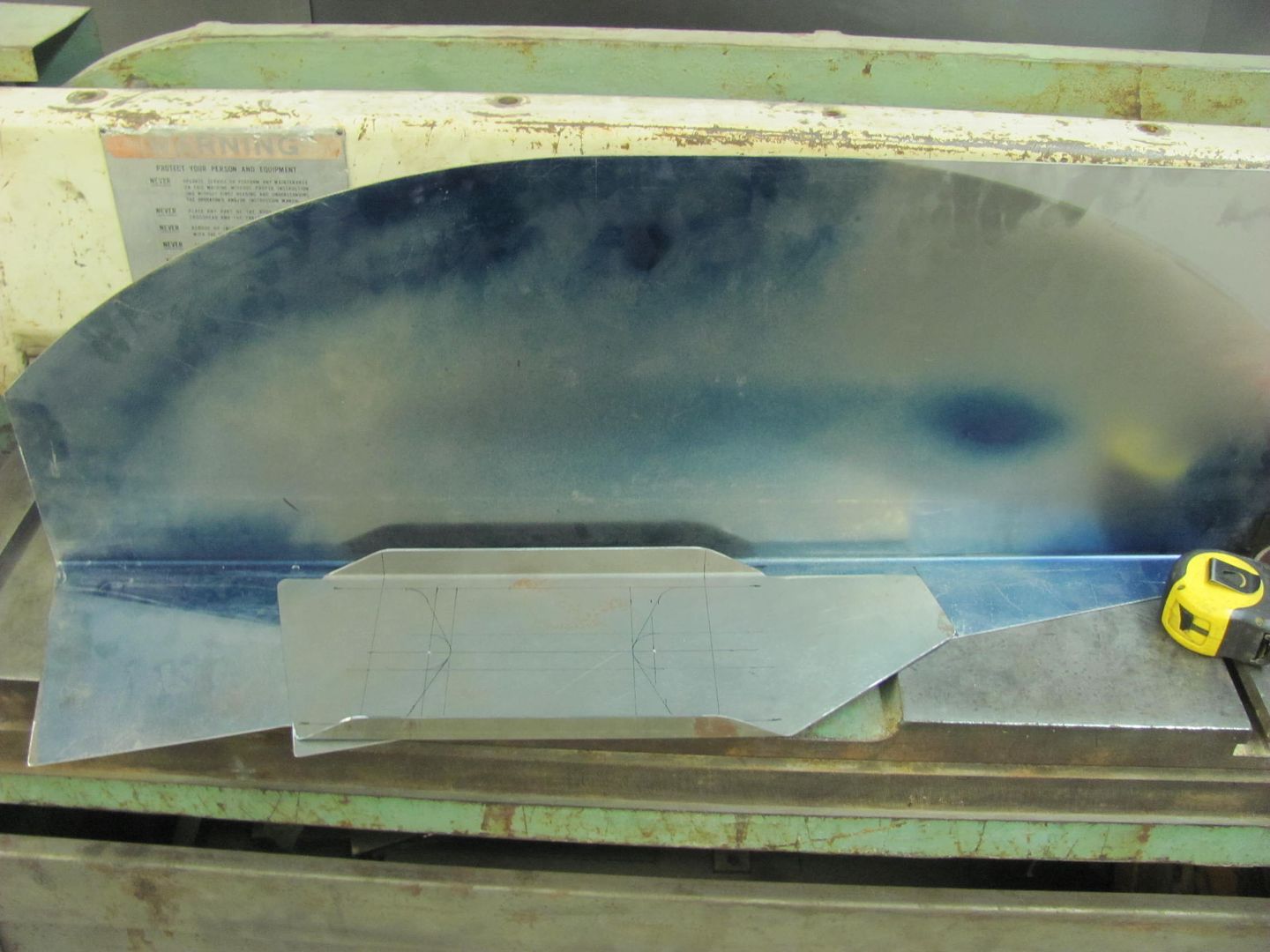
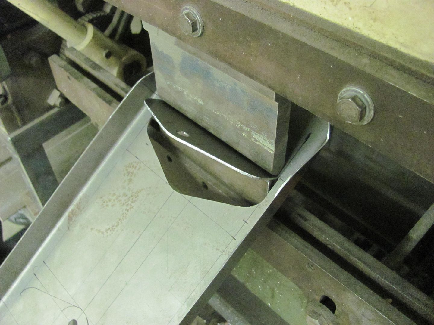
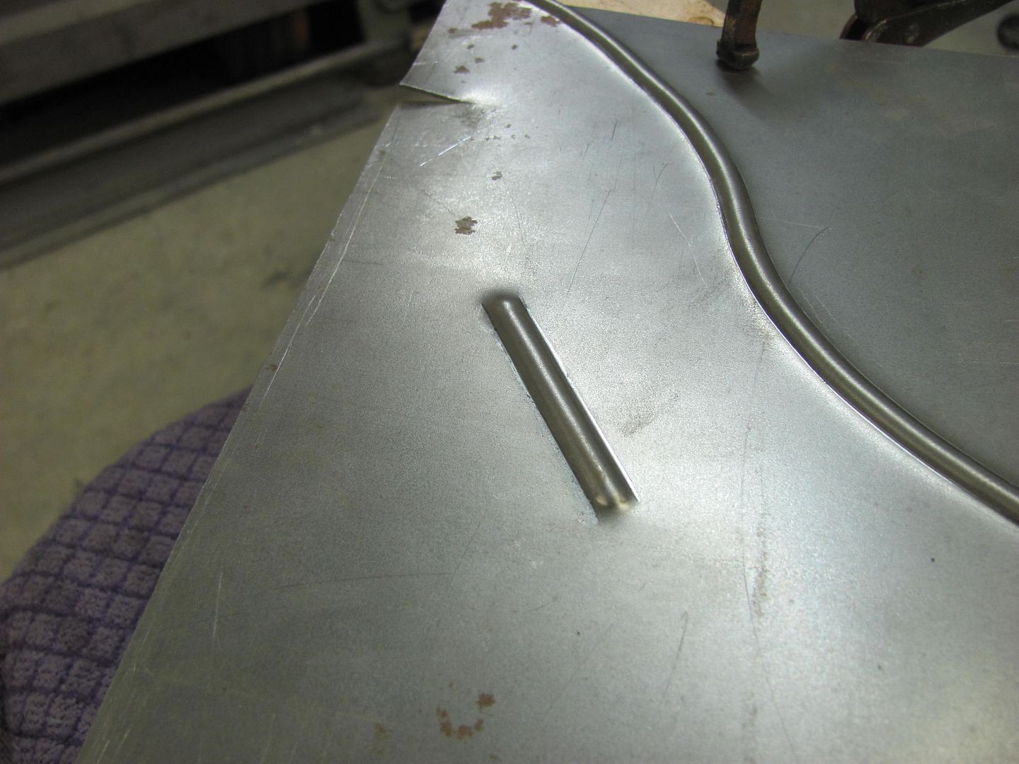
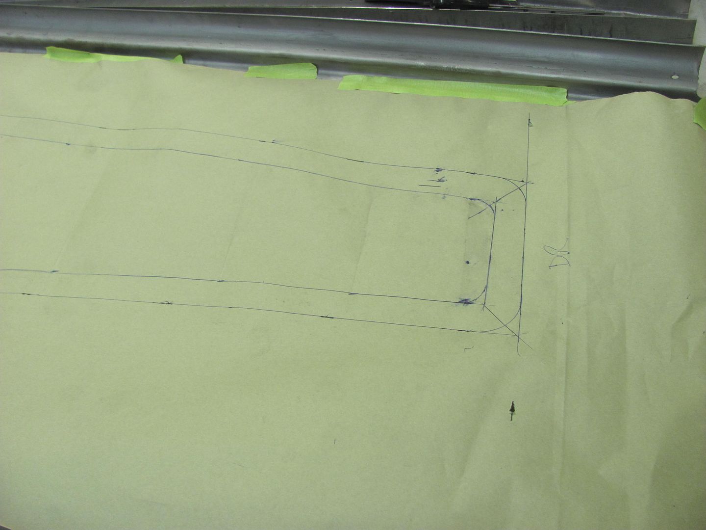
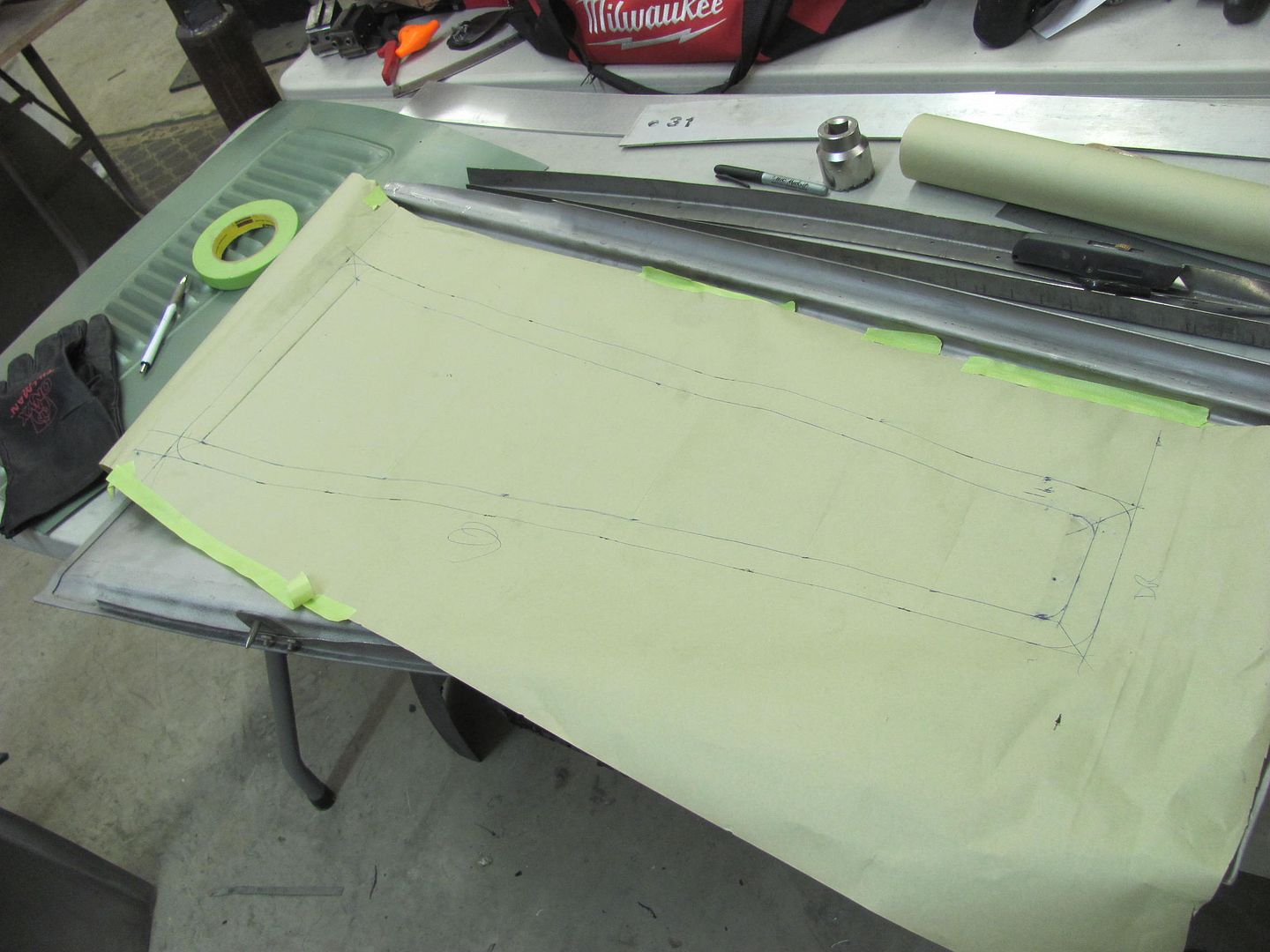
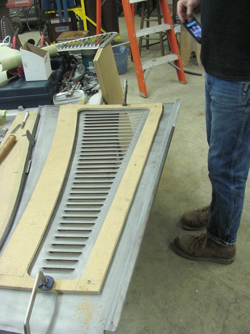
Well Cody posted up some pics today of the muffler "wrap" so I thought I'd add them here as a follow up for those that saw the post of us punching the stainless.


Picture%204410.jpg


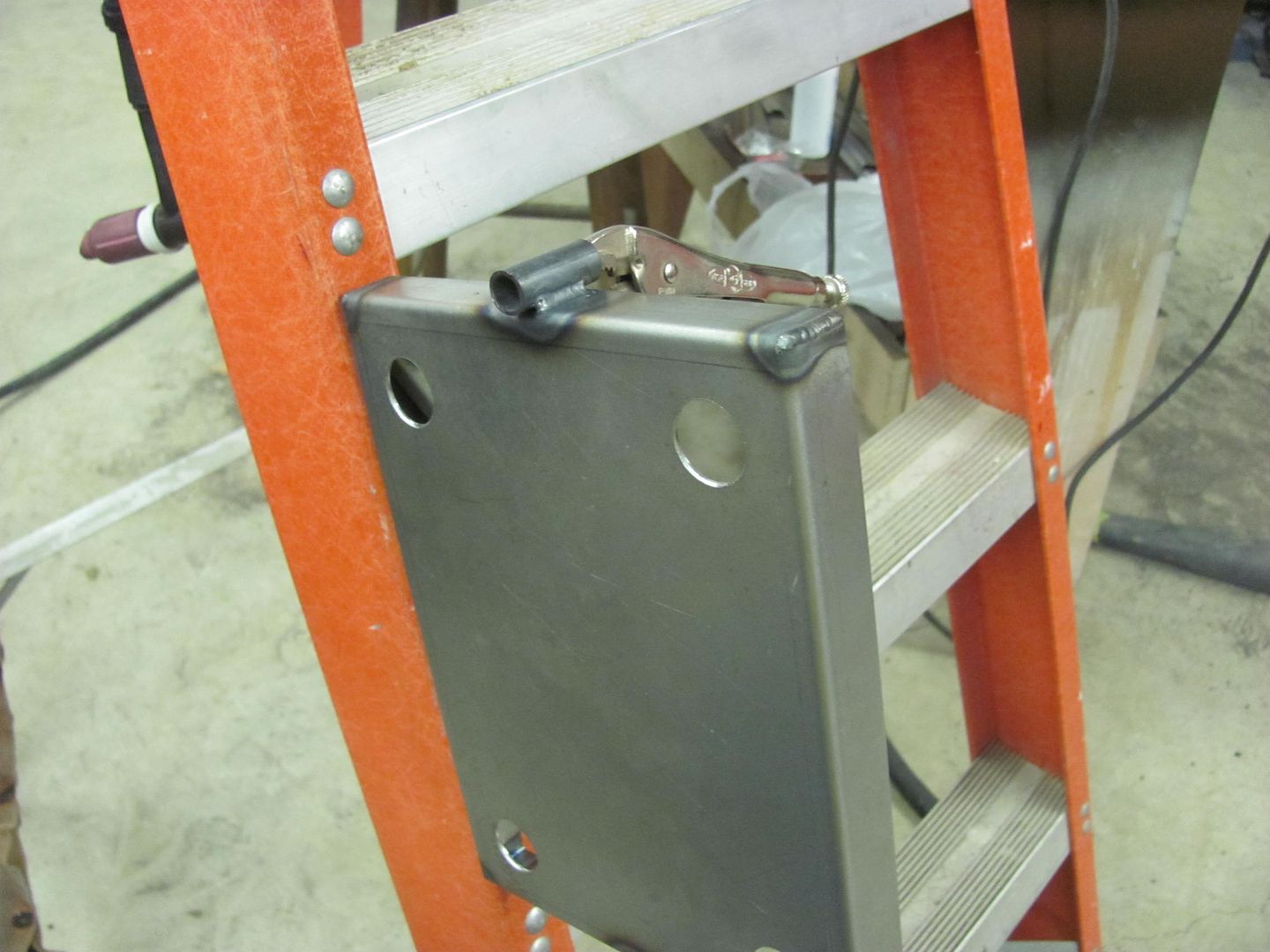
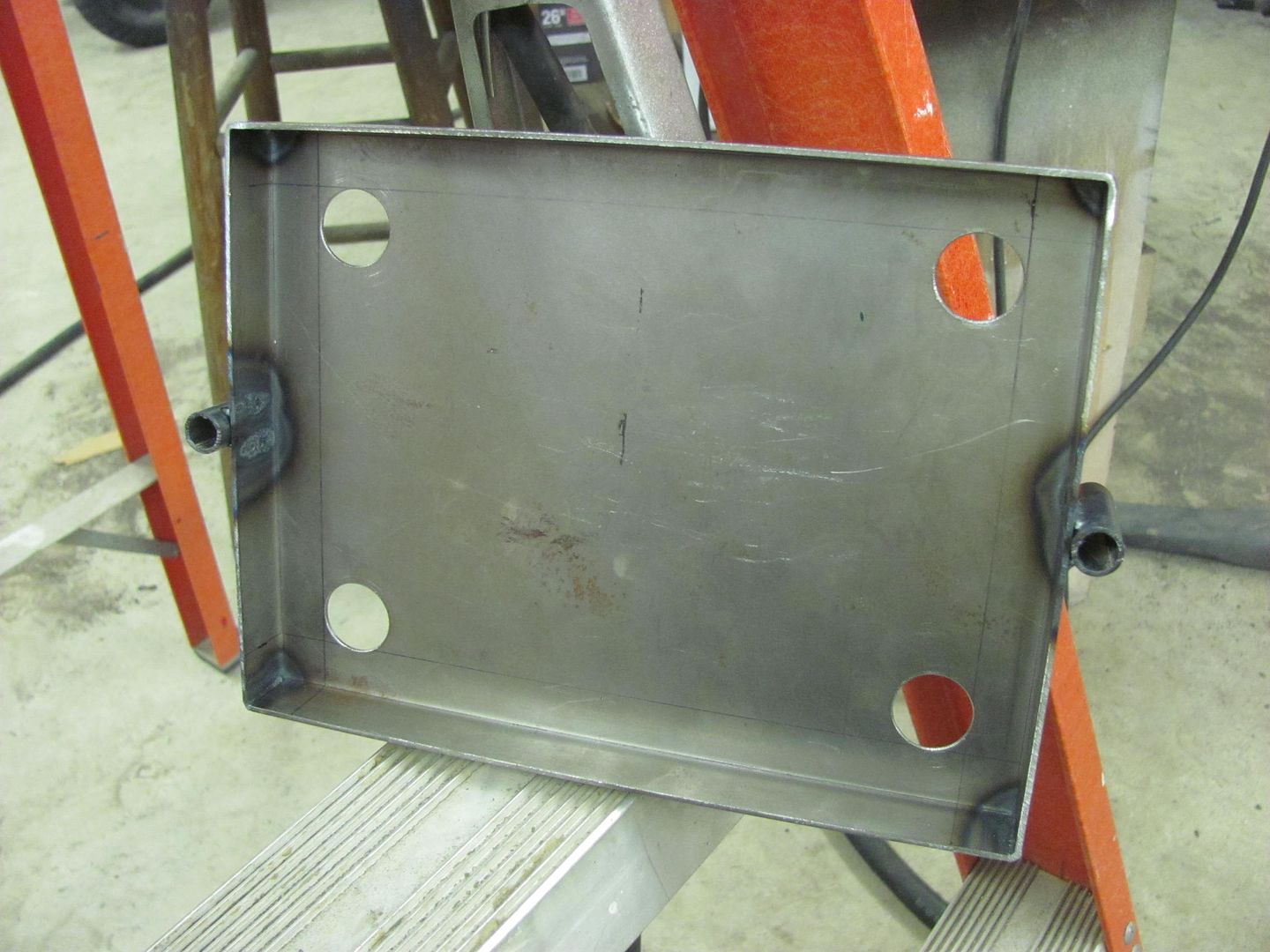
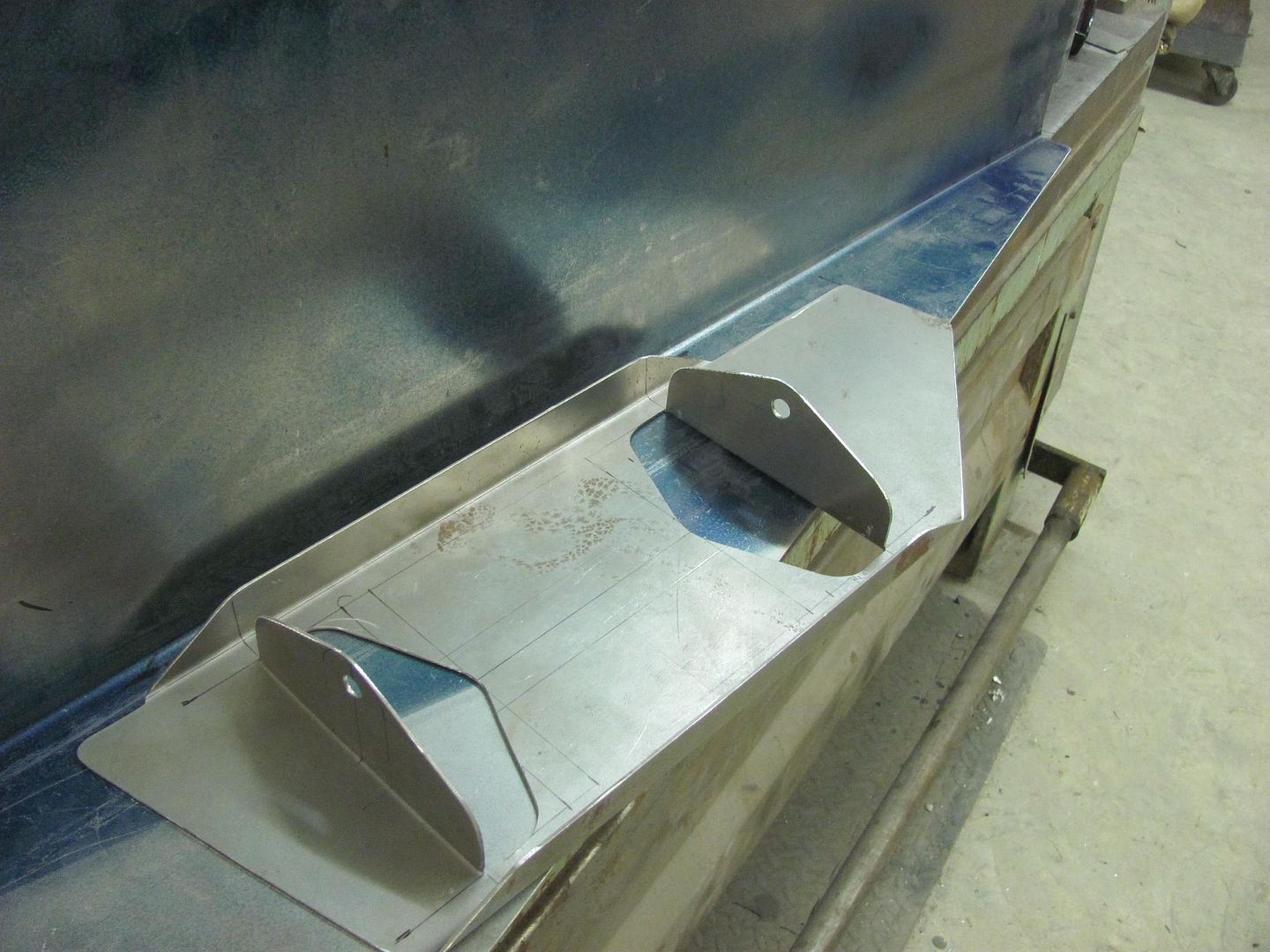
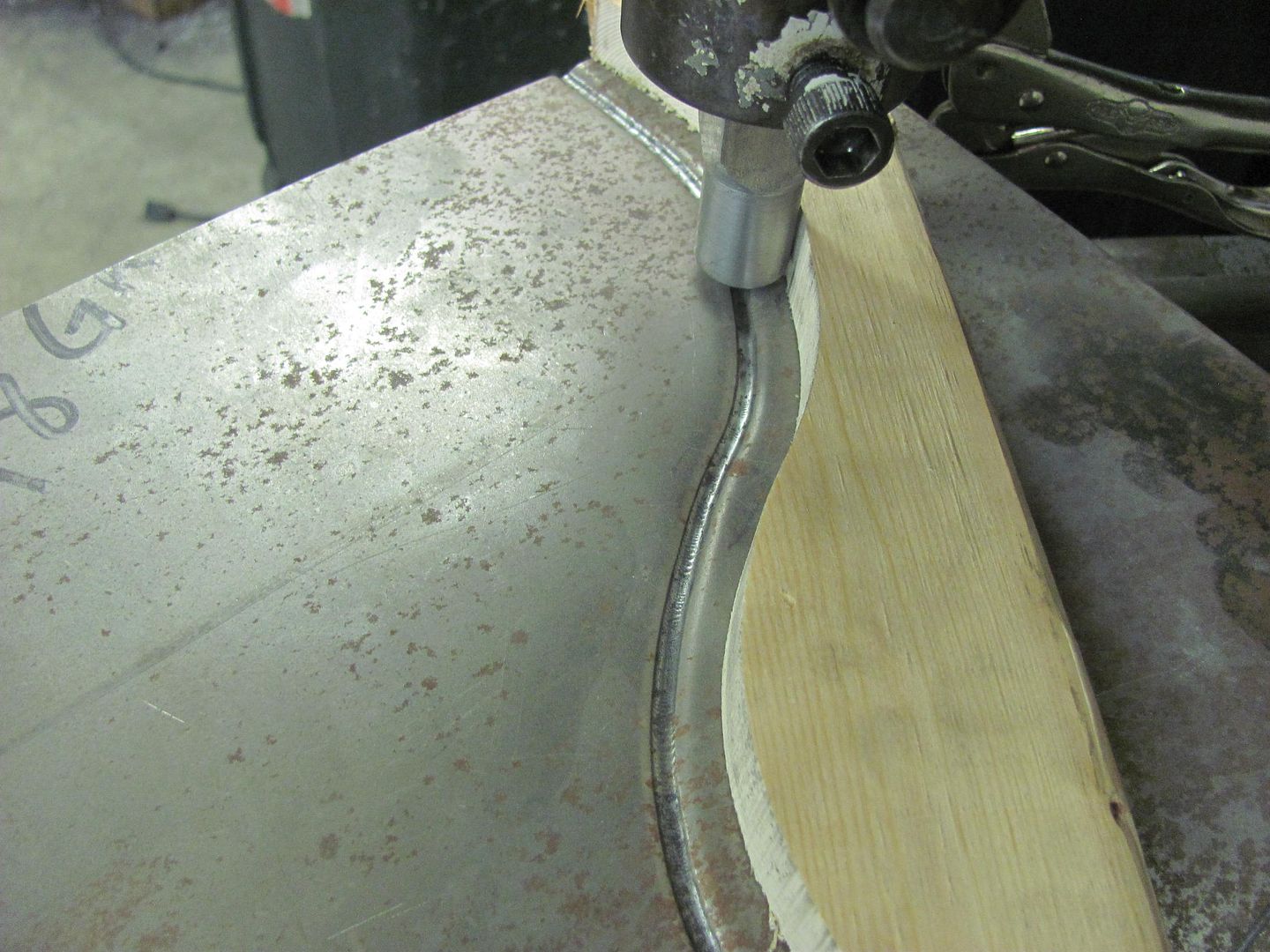
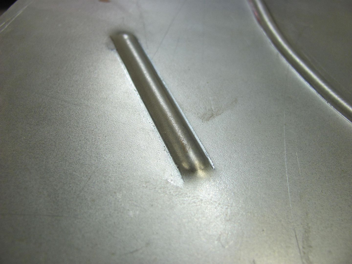
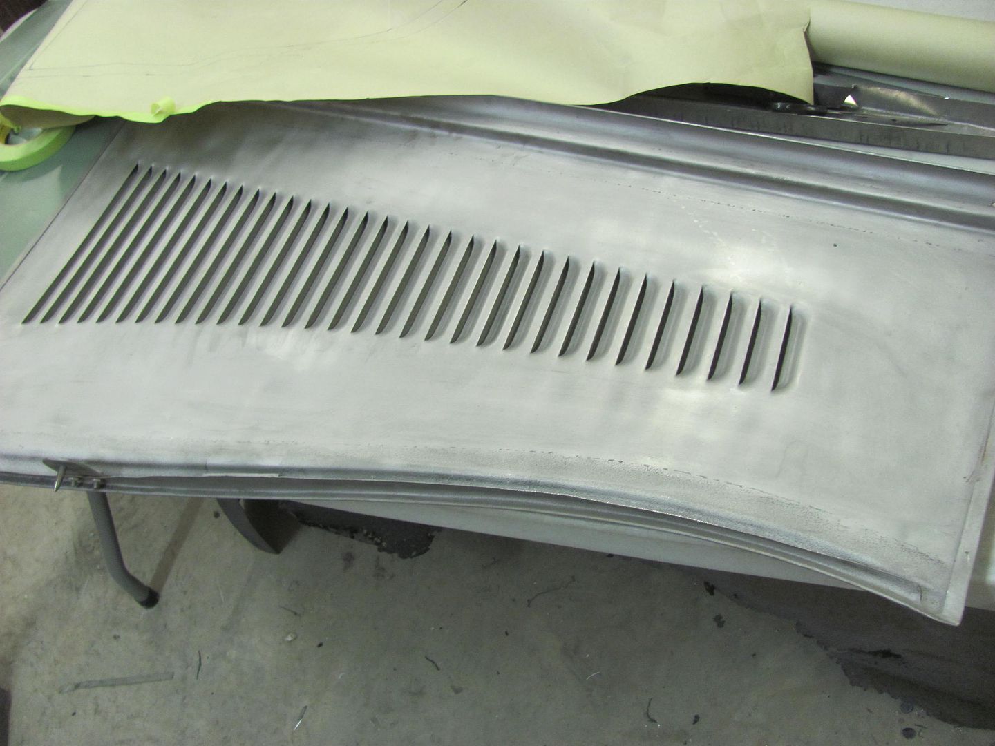
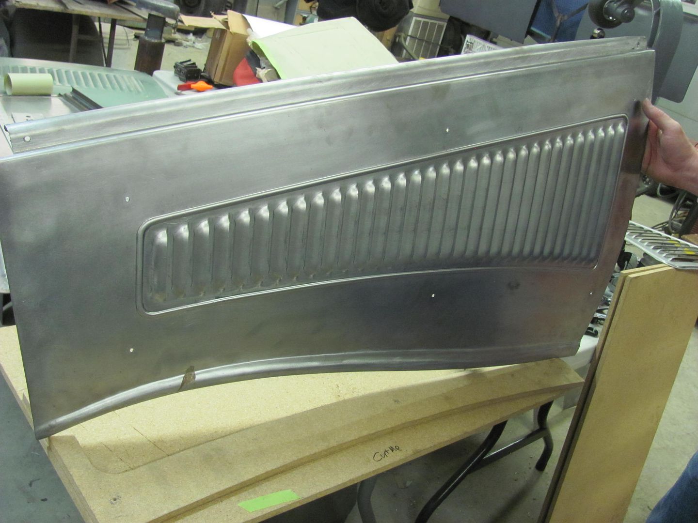
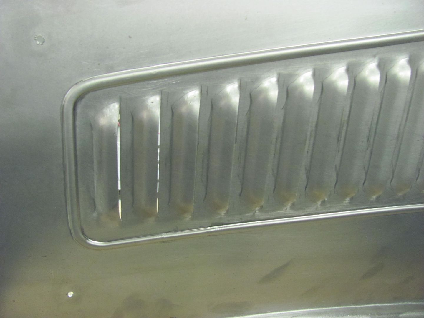
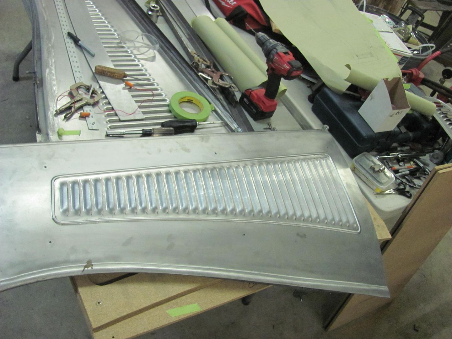
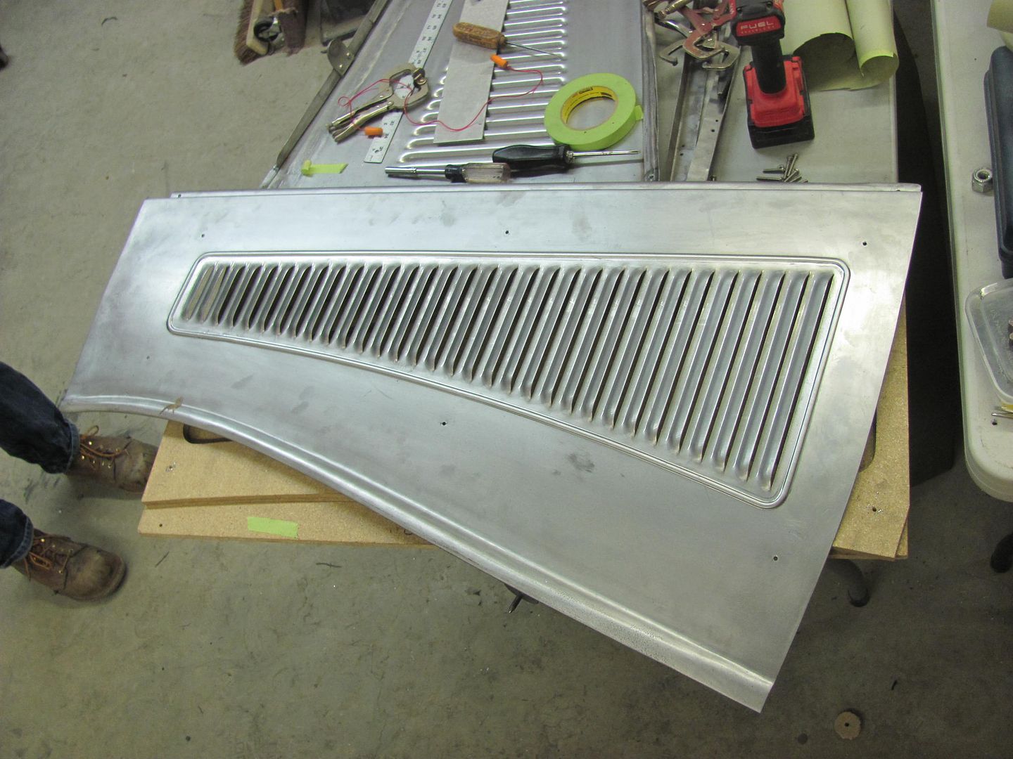
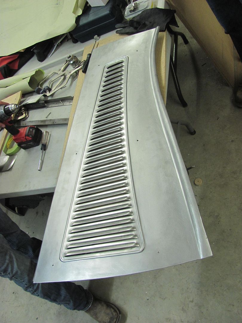
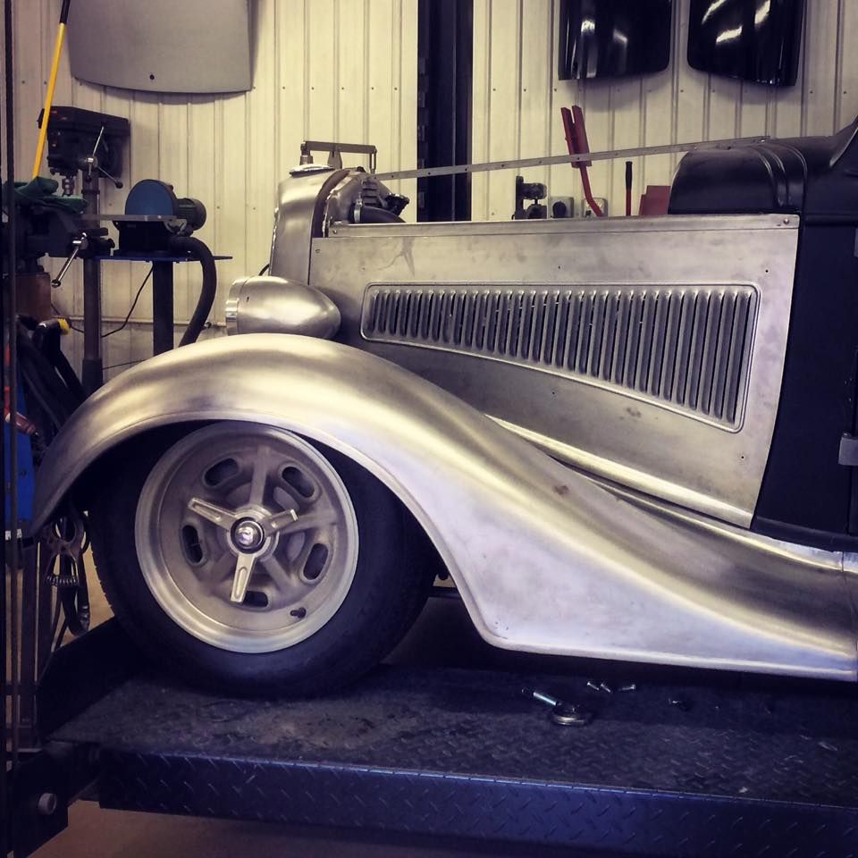
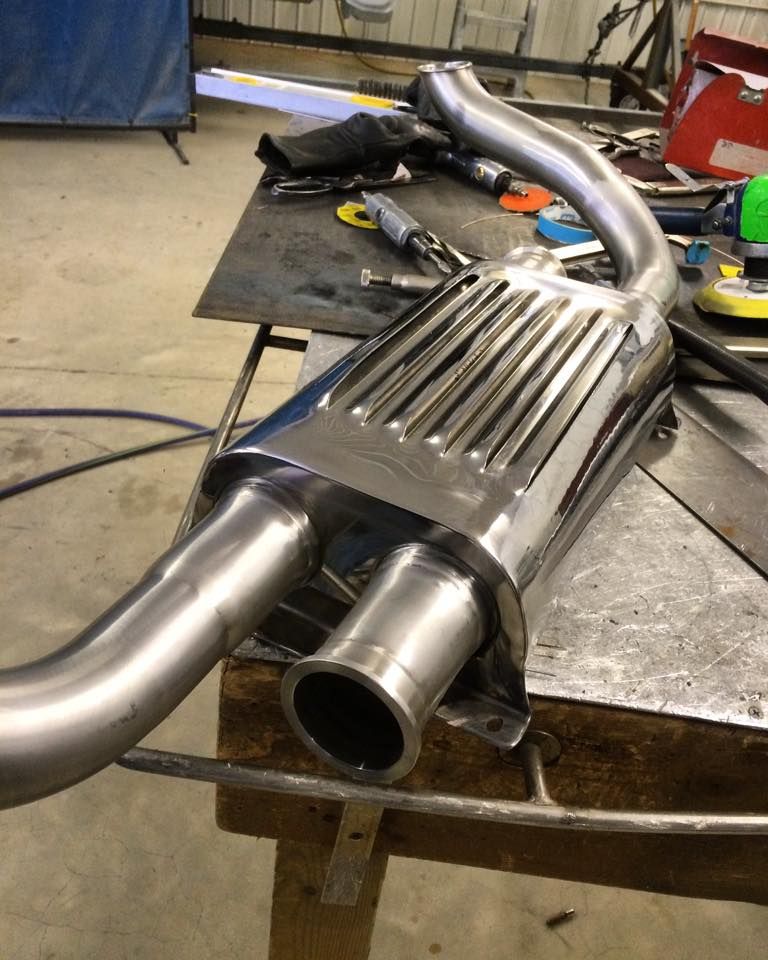
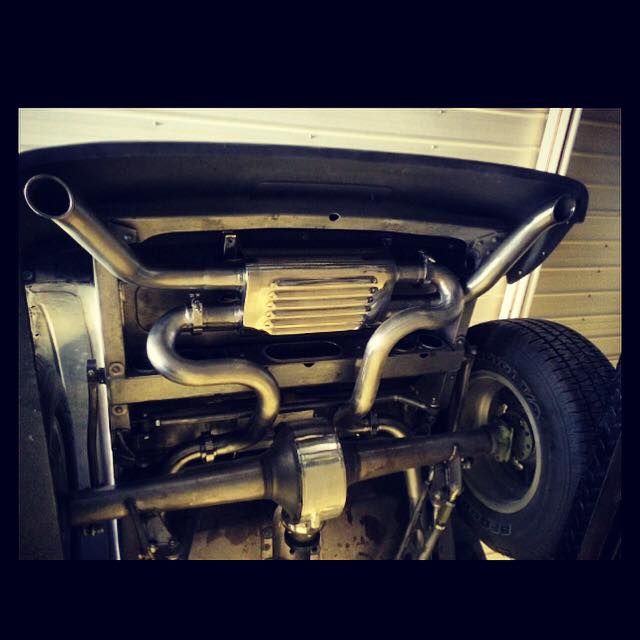
He's using stainless exhaust front to back, with two transverse mounted mufflers behind the rear axle. Since they are tucked up inside the frame rails, a bit of air flow will be provided by the louvers..


MufflerWrap1.jpg


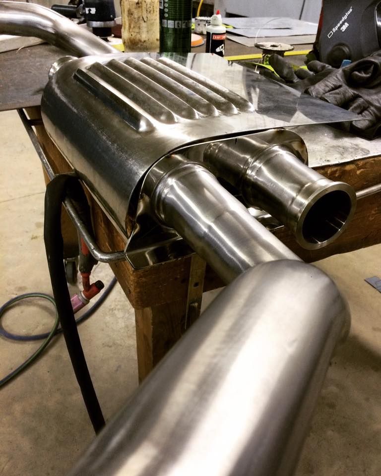
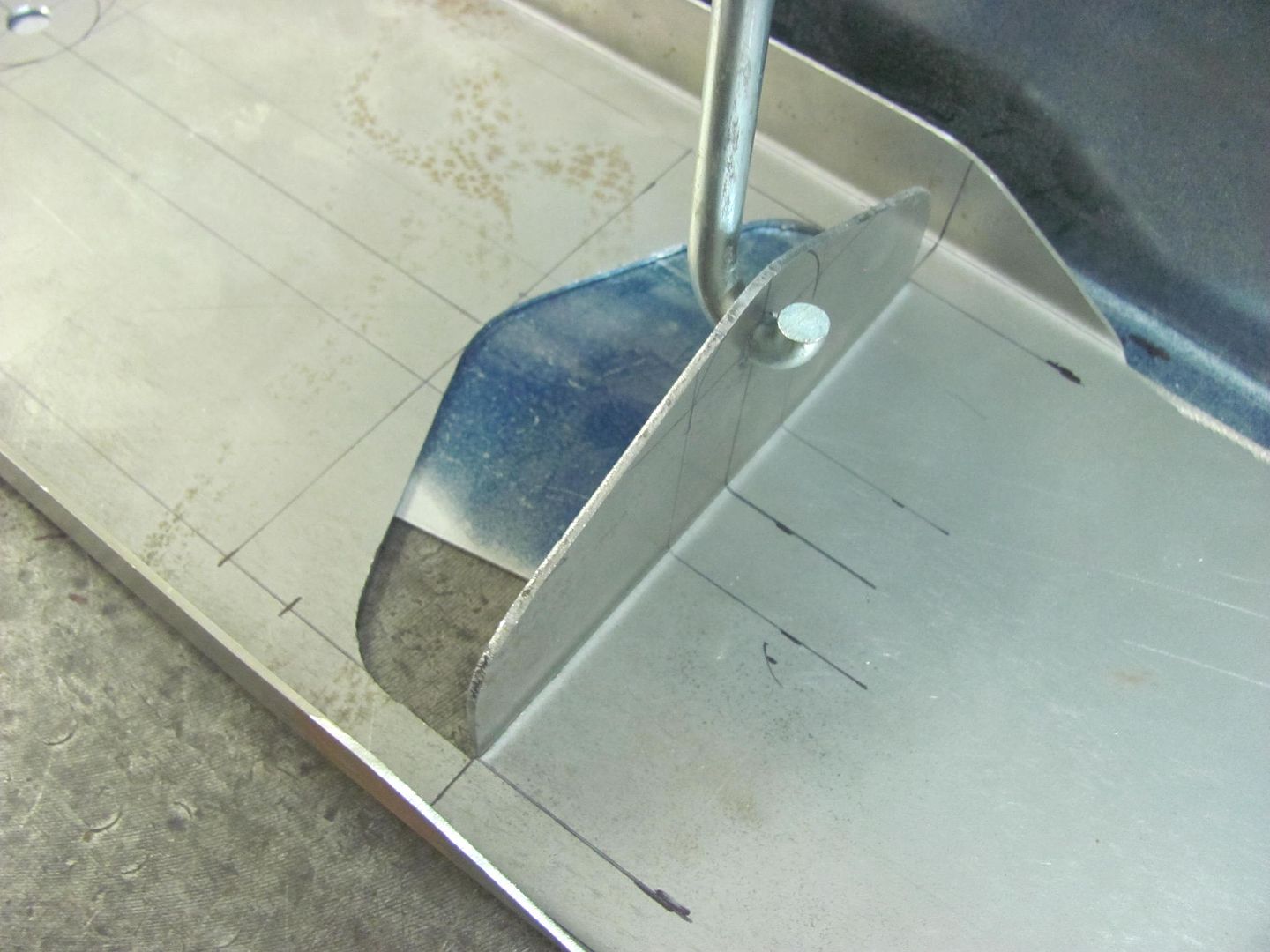
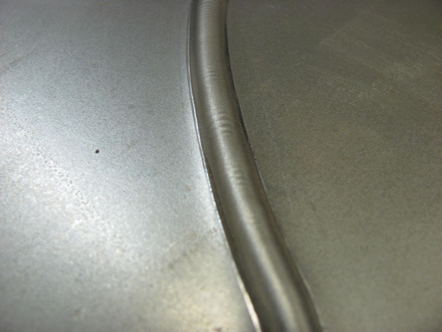
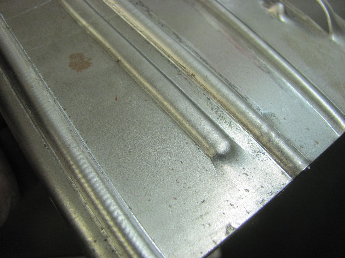
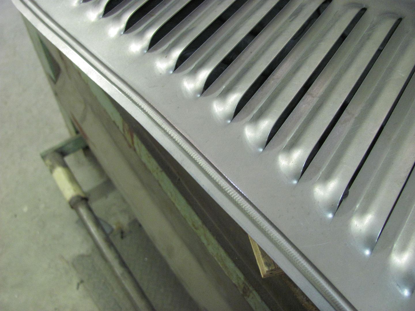
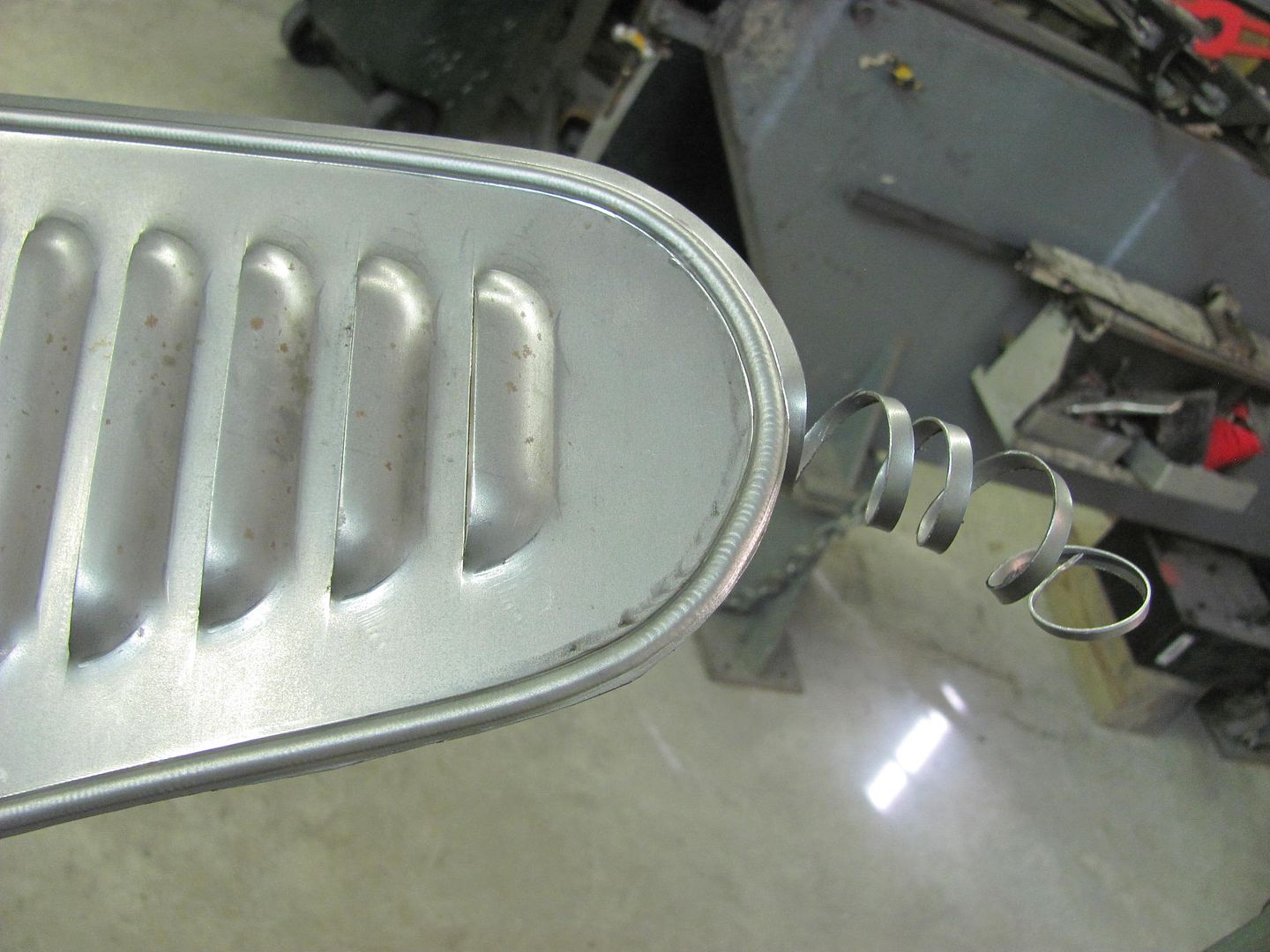
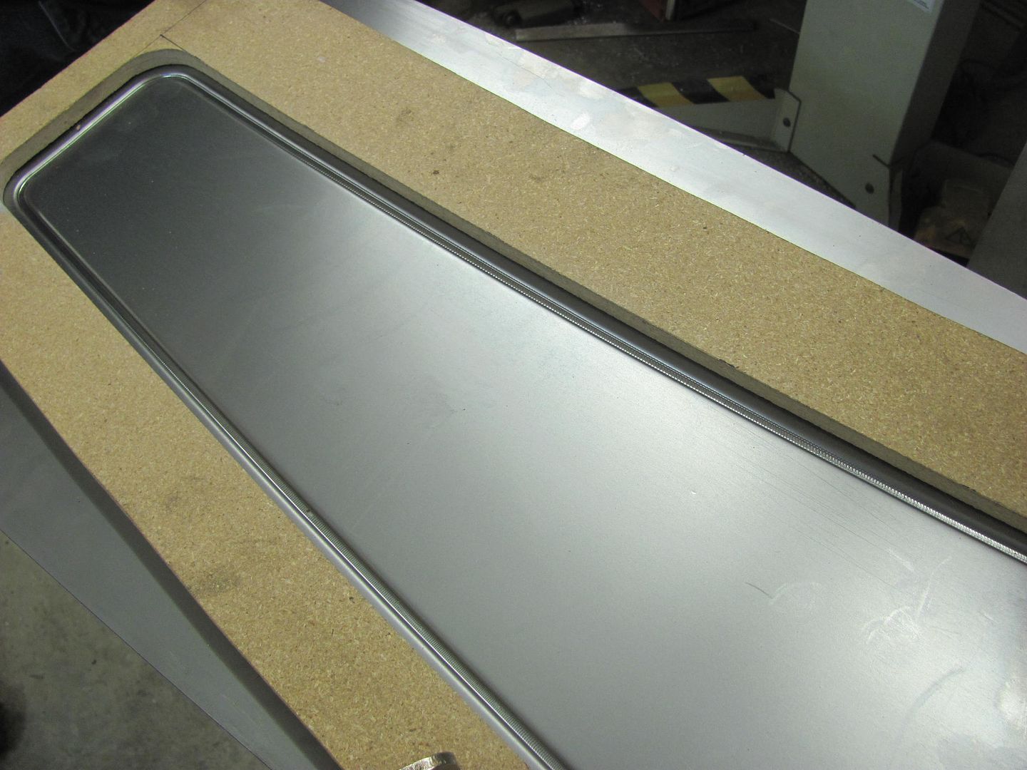
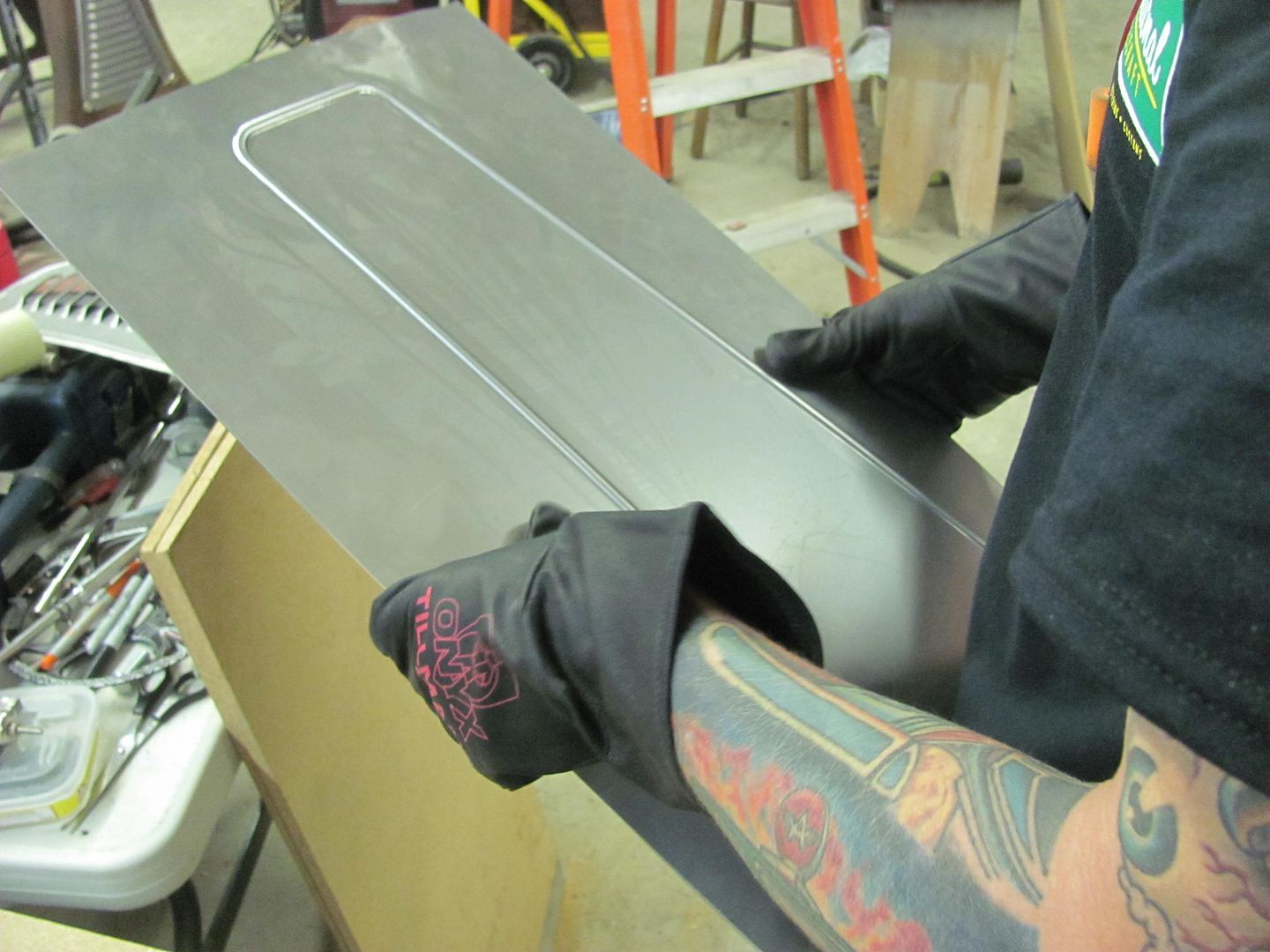
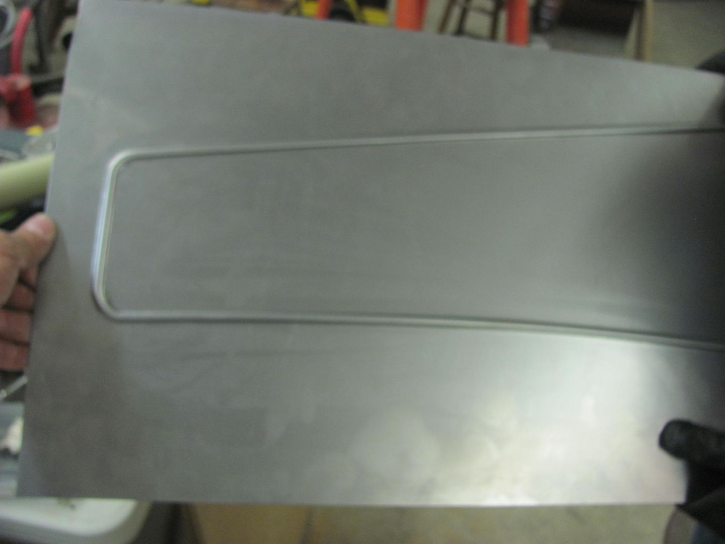
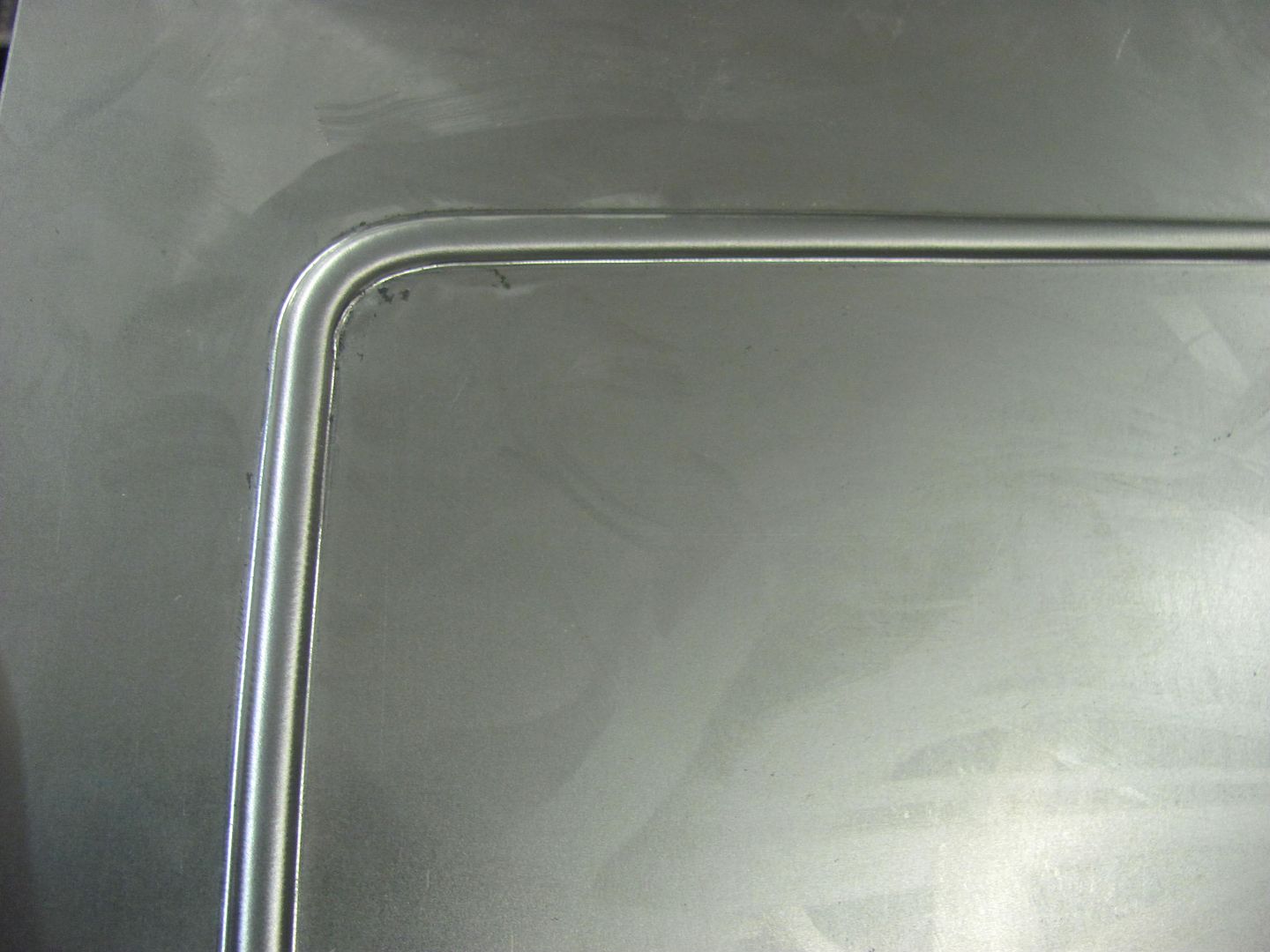
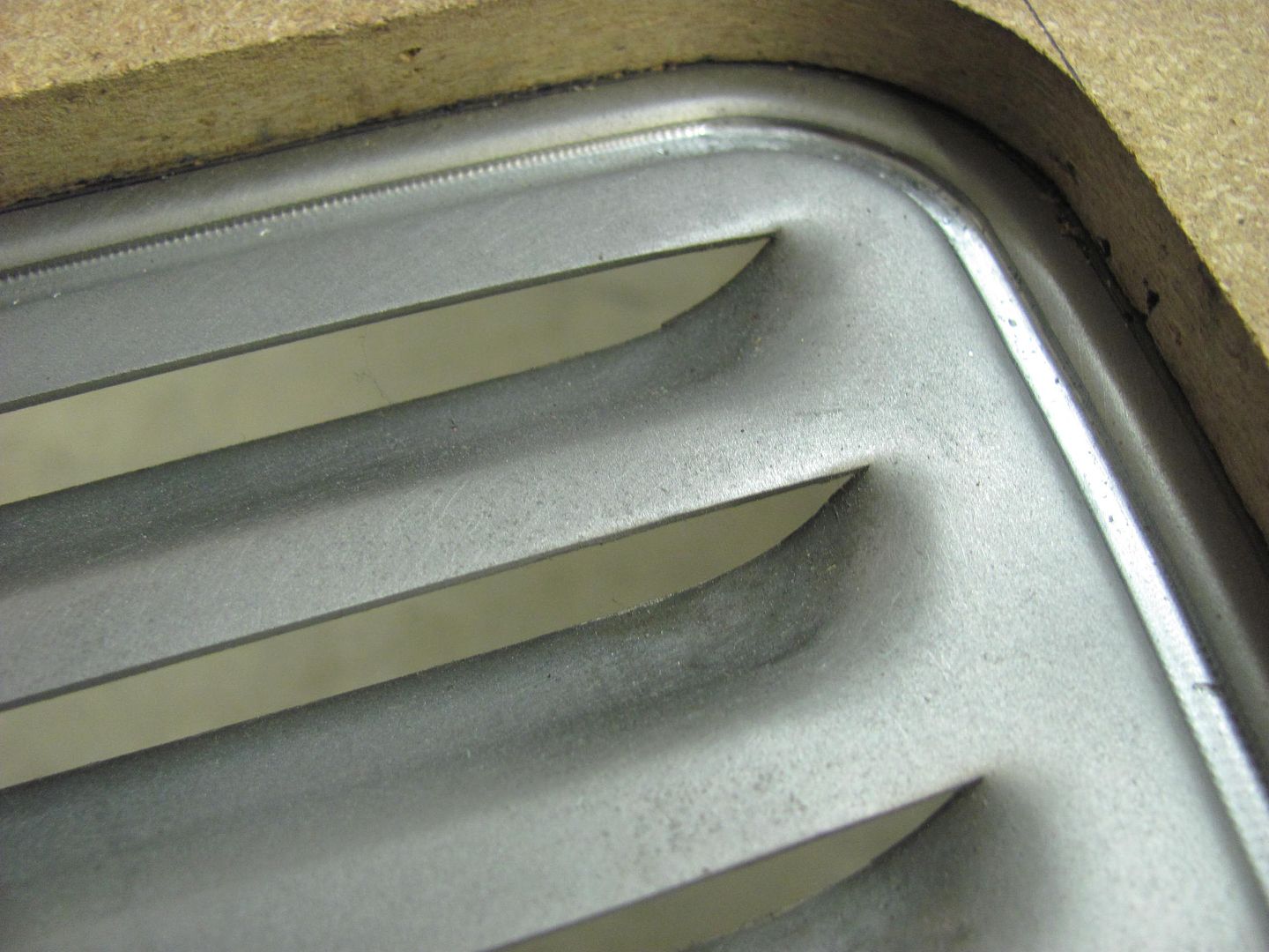
Note the "rolled" edge on the exhaust tail pipes. Cody says he isn't a fan of unfinished edges, and this car is loaded with such detail from one end to the other.


MufflerWrap2.jpg


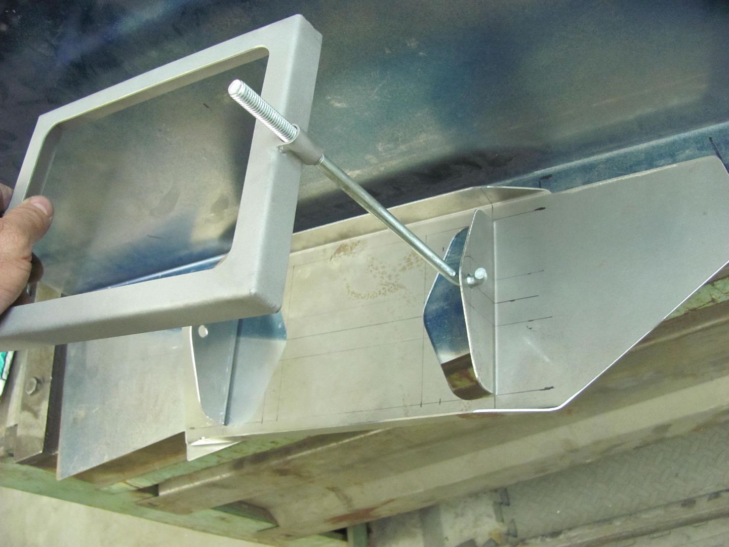
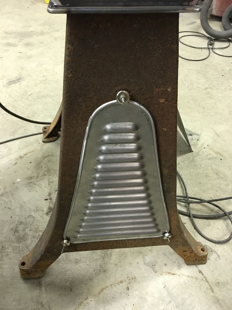
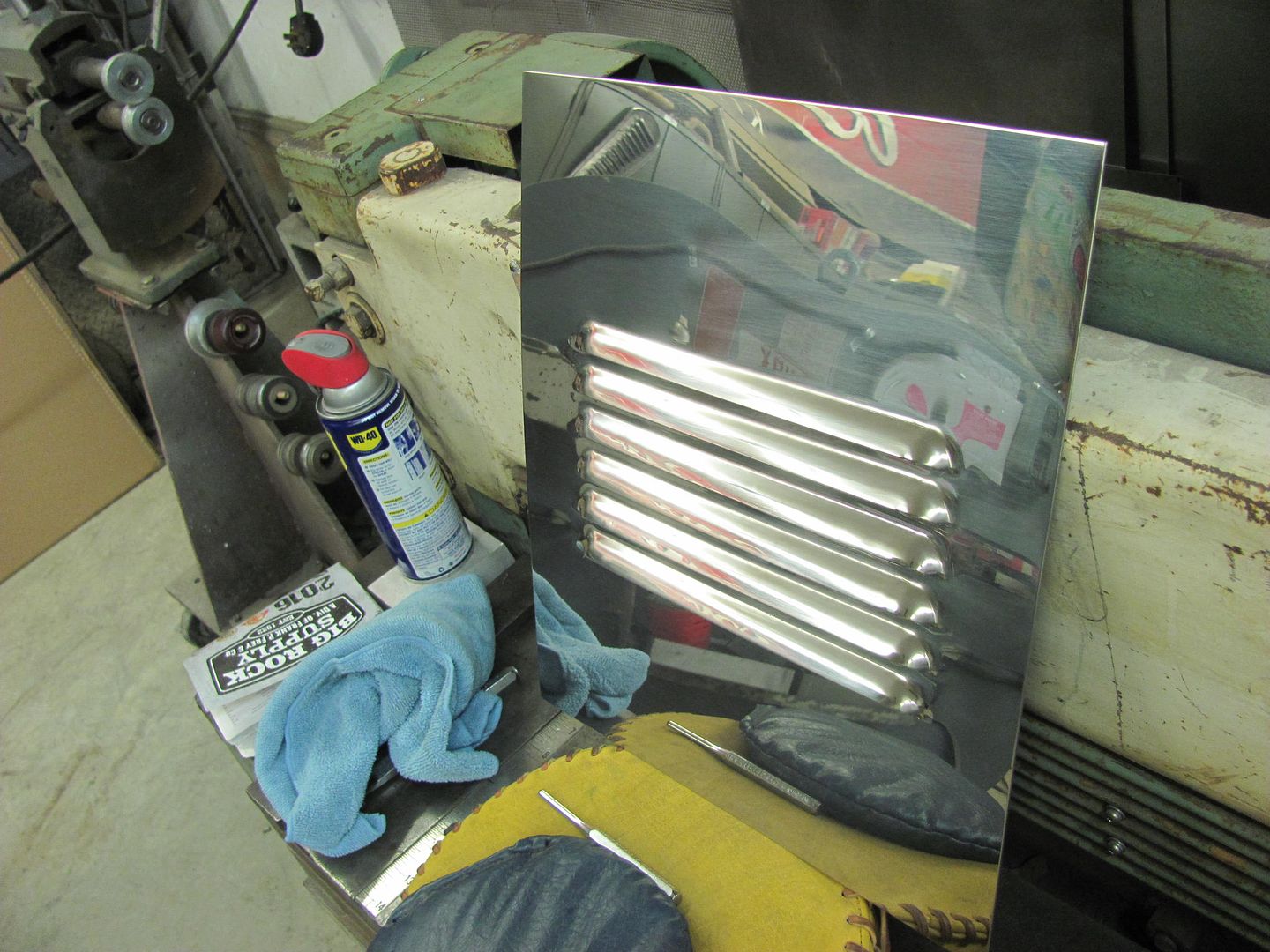
Installed, the louvers facing the front should give nice air flow.


MufflerWrap3.jpg


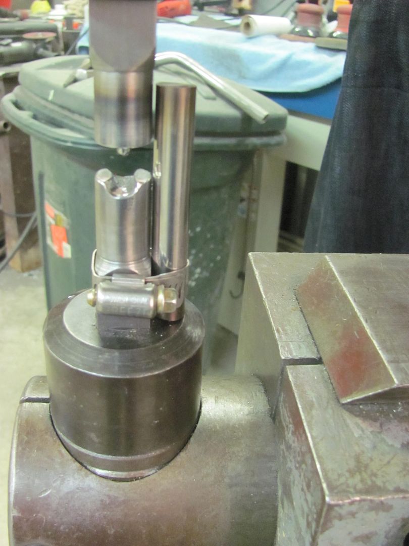
We've got another detail to work on with Cody, and it's been a nice change of pace to set the rusty metal aside and help out on his build with the louvers we've done. Thanks for the challenge!
 
Last edited:
To avoid these ads, REGISTER NOW!
OP
M

MP&C

Well-known member
Joined
Oct 21, 2009
Messages
4,396
Location
Leonardtown, MD
John's getting ready for engine start ceremonies, so I guess I need to get off my duff here. To help out in that regard, next we'll fabricate the battery tray which I don't believe came with the truck when John got it. Here's the best we have for a pattern:


Picture%204646.jpg


The hold down bracket for the prescribed Group 4 battery was with the truck, so we did some test fitting with the inner fender in place. It is a bit cramped for space, and John expressed concern of the availability of the Group 4 battery. Most local sources only carry the Group 1 in stock, which would also be a better fit.. So out with the old...


Picture%204644.jpg


I did miss getting in the flat pictures, but here is the freshly folded and welded hold down bracket for the new battery size.


Picture%204639.jpg


Picture%204640.jpg


All trimmed and prepped for paint..


Picture%204641.jpg


Picture%204642.jpg


Comparing the new to the old...


Picture%204645.jpg


Next will be the new battery tray.
 

larry4406

Well-known member
Joined
Jan 27, 2006
Messages
18,962
Location
Northern Virginia
Clever battery bracket! Looking at the old, I'm thinking welded angle iron, while you go at it with bent sheet stock! Did you use the magnet brake?
 

Kevin54

MEMBER EMERITUS
Joined
Jan 12, 2005
Messages
29,341
Location
Urbana, Ohio
MufflerWrap3.jpg


Robert......is this the underneath of Cody's car? What type of car is it, or did I miss that somewhere? I thought I was caught up on everything but possibly not.
 
OP
M

MP&C

Well-known member
Joined
Oct 21, 2009
Messages
4,396
Location
Leonardtown, MD
It's a 35 Chevy, it's the one he took to GNRS this past January. We did the hood louvers for it back in December..

Kevin, here are the pics I have of the car, took quite a few up at the Street Rod Nats in York PA a few weeks back. While taking pictures I spent as much time crawling under the car as studying the topside, awesome details throughout. Most people couldn't pick out half of the mods done unless they had a stock 35 sitting at home. ie: you can't find those tail light stanchions or headlight buckets in a catalog, they were all home made...


1935 Chevy By Cody Walls Slideshow| Photobucket
 
Last edited:
OP
M

MP&C

Well-known member
Joined
Oct 21, 2009
Messages
4,396
Location
Leonardtown, MD
...and now for the battery tray, shown here cut to size and sides folded up...


Picture%204650.jpg


Picture%204651.jpg


For the end folds, the cut was started using a .035 cutoff wheel..


Picture%204652.jpg


...and our trusty jig saw again...


Picture%204653.jpg


Picture%204654.jpg


Picture%204656.jpg


Picture%204658.jpg


Both ends complete, and frame holes have been piloted. Once checked to the hole spacing on the frame they can be drilled out for the 3/8 bolts.


Picture%204659.jpg


Picture%204661.jpg
 
OP
M

MP&C

Well-known member
Joined
Oct 21, 2009
Messages
4,396
Location
Leonardtown, MD
Got a "requirement" for some bead detail work and don't need the panels losing any of their shape. The bead roller does a nice job, but the forming process is more of a relocation of the metal from elsewhere, which would cause a panel to possibly lose some crown.

The Lennox (Pullmax) as a reciprocating machine does a better job of stretching the metal as the bead is formed, so there is less issue of losing panel crown.

Here we're making the female die in the South Bend milling machine.


Picture%204662.jpg


Ball end milling bit clamped in the chuck, square stock clamped in the Aloris tool holder..


Picture%204664.jpg


The ends of the tooling was also turned in the lathe to give a nice round feature that will work better for use with a guide.


Picture%204665.jpg


Picture%204667.jpg


Picture%204666.jpg


Test run...


Picture%204668.jpg


Nice crisp lines, the "chatter" should be cleaned up if I can get the feed speed more consistent. The small diameter of the upper die's "punch" provides the needed stretch, with the downside being the marking from too fast of a feed speed. Making the upper die in more of an oval shape will eliminate most of the marking, but it won't stretch as well.. To keep from losing panel crown, stretch is our preference here..


Picture%204669.jpg


This shows how well the die provides stretch, when you can add a bead in the middle of a panel....


Picture%204672.jpg


......and there's no distortion on the ends of the bead on an otherwise flat panel..


Picture%204674.jpg
 
OP
M

MP&C

Well-known member
Joined
Oct 21, 2009
Messages
4,396
Location
Leonardtown, MD
Thanks for the comments!


How much force was used for that?


Force applied for feeding the panel? It did bind up a bit when navigating the curves as the lower die should have wider relief on either end of the "channel" to accommodate curves in the bead. As is, when you attempt a curve it binds on the sides of the bead, which may be some of what you are referring to. In all, it wasn't too much force applied, it was a combination of applying said force while also attempting to apply restraint to keep chatter marking down to a minimum. Taking care of the lower die should help the panel "flow" through more easily, which will help for better consistency in feed speed..
 

rmalkow2

Well-known member
Joined
Jun 26, 2009
Messages
4,087
Location
Brighton, MI
Thanks for teaching us yet another fantastic method of crafting metal. I've never heard of this process before but seeing you do this it makes so much sense. I'm always anxious to read your posts and learn something new.
 

johnyg

Well-known member
Joined
Nov 11, 2015
Messages
319
Location
boca raton fl
hi robert...i really enjoy your ingenuity on these projects.....i just hope you are well compensated . i used to do some "fancy" home remodeling and always seemed i did it for my own satisfaction. thank you for your time...john.
 
OP
M

MP&C

Well-known member
Joined
Oct 21, 2009
Messages
4,396
Location
Leonardtown, MD
Thanks for the comments guys! Not much to show on the 55, we've been block sanding, metal bumping, adding filler, lather, rinse, repeat. On the beading dies from the other night I wasn't too pleased with the shape, IMO they were too rounded. Especially for where this will be used, it needs to better match the rest of the car. So another upper die was made using a more blunt end tip with a slight ramp.


Picture%204681.jpg


The lower die was relieved to better accommodate tighter corners...


Picture%204682.jpg


Comparing the two dies....


Picture%204688.jpg


Looking at the center two sample beads, the one toward the left shows a flatter bead using the new die..


Picture%204685.jpg


And on the Wheeling Machine front, I've been contemplating a storage drawer for under the base, but have struggled to find a good slide track to hold it.. Until yesterday, the guys at Dyna Rep Company came through for me, a 6" long full extension slide, in stock! Thanks Brad!


IMG_1271.jpg


These will be mounted between the mounting legs coming in from the side, drawer deep enough to hold all the extra lower anvils and hopefully the goKart slick...


English%20Wheel%20031.jpg
 

mopar4don

Well-known member
Joined
Mar 9, 2013
Messages
103
I have a question about the welding wire you use (ER70S-7)
I have been using the ESAB spool arc easy grind which I believe is the equivelent.

Anyway can I use the easy grind when welding sub-frame rail structure to rocker panels.
Or would the ER70S-6 (which is a bit harder) work better for plug welding non showing structure?
Thanks for all you do
Don
 
OP
M

MP&C

Well-known member
Joined
Oct 21, 2009
Messages
4,396
Location
Leonardtown, MD
I wouldn't have any reservations of using the easy grind. Those rails and rockers are still likely a 19 or 18 gauge, same as most of the other sheet metal you're using the EZGrind on...
 
OP
M

MP&C

Well-known member
Joined
Oct 21, 2009
Messages
4,396
Location
Leonardtown, MD
Thanks!


Cody travelled down today from Milton DE so we could add some bead detail surrounding the louvers on the hood sides.


Picture%204693.jpg


He used a paper pattern to copy the louver layout from the hood sides, and then added the offset for the bead location.


Picture%204694.jpg


Picture%204695.jpg


While he was doing that Kyle and I added the rounded bead detail to the louver panels for the Wheeling Machine, here using a fancy clamp-on guide...


Picture%204690.jpg


Beaded....


Picture%204691.jpg


Motion picture of same..


Excess flange is trimmed to the bead edge...


Picture%204692.jpg


This should give a more finished edge when attached to the cast legs...


IMG_1400.jpg


Once Cody was done with the layout and transferred it to some 1/2" thick MDF, it was cut out on the fancy vice jigsaw...


Picture%204696.jpg


Picture%204653.jpg


The corners were dressed with a 1-1/2" diameter drum sander and all the other edges filed to remove any imperfections that may alter the course of the beading dies. Then a sample of 18 gauge was clamped and run through the dies to insure the corners wanted to play nicely... The dies in the Lennox were changed to the flat upper for a flatter bead profile.


Picture%204686.jpg


Picture%204697.jpg


Picture%204699.jpg


Picture%204700.jpg


Picture%204701.jpg


With that looking good, the MDF guide was located on the hood side, clamped temporarily with some vise grips, and drilled for 8-32 machine screws to secure it in place..


Picture%204703.jpg


Cody positions the IPhone for the video, using the patent pending Vise Grip phone clamp.


Picture%204704.jpg


Completed panels...


Picture%204706.jpg


Picture%204707.jpg


Picture%204708.jpg


Video of the process....


One pass was made most of the way through to give a good amount of stretch, and a second pass a slight bit more to add some definition..


Picture%204709.jpg


Picture%204710.jpg


Picture%204711.jpg
 
Last edited:
To avoid these ads, REGISTER NOW!

EdT

Well-known member
Joined
Sep 21, 2010
Messages
1,104
Location
North Georgia
Beautiful work and, as always, very educational. Thanks for all the extra effort to document your work. It's a big help to those of us behind you on the learning curve. Just out of curiosity, how many man hours would you guess are in one side panel from flat sheet to finished part including development and testing of the tooling and associated processes?
 
OP
M

MP&C

Well-known member
Joined
Oct 21, 2009
Messages
4,396
Location
Leonardtown, MD
Ed, thanks for the comments and questions. We didn't do the original work to remove the 3 horizontal factory louvers, the sectioning, stretching, and pinching that took place on the hood, so I can't speak to that (Cody's work). For the owner test samples and the additional sample the day of the "official punch" and then both of the two hood sides, we had about 20 man hours in that, not counting Cody (guessing as I don't have time cards in front of me). For the bead work this past weekend, we had approx. 9 to 10 man hours, not counting Cody. Next comes all the paint prep, Cody says it will be every bit of 10 hours per hood side. Sanding primer around louvers is not fun, much less adding a bead detail around them.

For the bead tooling, this is something I did not charge for as it can/will be used on other projects, likely to include the 55 wagon (we have some new inner fenders for the engine compartment to fabricate). If it were tooling strictly made for one particular project, it would be billed out..
 
OP
M

MP&C

Well-known member
Joined
Oct 21, 2009
Messages
4,396
Location
Leonardtown, MD
Cody posted up a picture today of the hood side installed on the car. I definitely think the bead detail looks better, refines it a bit..


35ChevyHoodBead.jpg
 

Craptain

Well-known member
Joined
Apr 18, 2013
Messages
4,026
Location
Tampa Bay FL
Cody posted up a picture today of the hood side installed on the car. I definitely think the bead detail looks better, refines it a bit..


35ChevyHoodBead.jpg
I agree wholeheartedly. The whole project is coming together nicely.

Sent from my LG-D801 using Tapatalk
 

E12-535iTurbo

Well-known member
Joined
Feb 27, 2014
Messages
492
Location
The Netherlands
It is such a please to watch this. I recently started a new job in an office department losing both the practical side of my work as well as my parental leave. So I'm back working full time again in an office. It kinda hurts to watch fun things like this. Perhaps I should reconsidder..........
 
OP
M

MP&C

Well-known member
Joined
Oct 21, 2009
Messages
4,396
Location
Leonardtown, MD
At least you can check out the GJ "resources" in the office environment... :D


Not much to show on the wagon lately, been block sanding, metal bumping, filler, block sanding, etc.

In the meantime, tackling something on the HDL, need to add some knobs on kitchen cabinet doors. Rather than measure out each door, lets make some templates..


A corner was notched, then the flanges folded at 90*. The location measured and drilled. A mirror image was then bent so we can have a left and right, clamped together, and drilled through.

IMG_1417.jpg


IMG_1418.jpg


Then just hold it up to the cabinet door and drill through...


IMG_1419.jpg


IMG_1420.jpg
 

PugetDude

ALLIANCE MEMBER
Joined
Mar 13, 2013
Messages
22,263
Location
Superstition Mountains, AZ
At least you can check out the GJ "resources" in the office environment... :D


Not much to show on the wagon lately, been block sanding, metal bumping, filler, block sanding, etc.

In the meantime, tackling something on the HDL, need to add some knplasticobs on kitchen cabinet doors. Rather than measure out each door, lets make some templates..


A corner was notched, then the flanges folded at 90*. The location measured and drilled. A mirror image was then bent so we can have a left and right, clamped together, and drilled through.

Nice job, Robert. Had to drill hundreds of holes for door/drawers on my recent remodel, so I built something similar with a scrap of acrylic and strips of 1/2" plywood. (Don't have your metalworking skills or tools). One thing I discovered is that a brad-point drill bit doesn't work well on drilling the holes- it scored a full-diameter plug through the acrylic lacquer finish, which then spun on the bit, preventing it from cutting any deeper. Ended up using a standard twist drill with a stop collar to keep from blowing out the back side of the cabinet door.
 

stsmytherie

Well-known member
Joined
Dec 16, 2005
Messages
171
Location
VT
Nice!

What little wisdom I've gained with age and experience mostly tells me that templates, jigs, and fixtures (and scripts, and boilerplate responders, and...) are almost always worth the trouble. Save the energy and effort for edge cases.

One of the first tools I built when I learned to weld was a jig for drilling bolt holes in the corners of squarish things.

26533280191_933ca7d0e4_z.jpg
 

aggierailroad

Well-known member
Joined
Jan 8, 2012
Messages
581
Location
Houston, TX
Looks great per usual, Robert!

Any chance you've ever done any spin forming? I'm looking to knock out a few lamp shades and would appreciate any tips.
 

TimeWarpF100

Well-known member
Joined
Aug 21, 2010
Messages
6,784
Location
not here
I've not tried it myself to speak fluently, but if you're on FB, there is a metal spinning group (private group to mitigate spammers)

https://www.facebook.com/groups/526540047361369/

I think the extra bead on the hood side and your english wheel look fantastic. Others will be trying to copy that..

I hit the join button for metal spinning group too. Always been really fascinated by it.

I had a piece made for the Siren on my '66 F-600 as originals had a tendency to crack.
 
OP
M

MP&C

Well-known member
Joined
Oct 21, 2009
Messages
4,396
Location
Leonardtown, MD
Tonight we did some testing of welding wire. "Mr onetwo" (Mark) had sent me a PM a week or so ago and we both ordered some ER70S-7 welding wire from Blue Demon in .023 diameter.

Picture%204721.jpg


I have a Miller 211 Mig, and here is the heat settings, and you can also see around the dial the "suggested" material thickness for said settings.


Picture%204720.jpg


Before changing out the wire in the machine, lets do a test of the .023 EZ Grind wire.


Picture%204712.jpg


rear view of weld penetration.....

Picture%204713.jpg


Then changed to the .023 ER70S-7 wire with no change in the heat settings...


Picture%204714.jpg


rear view of weld penetration....

Picture%204715.jpg


Even though we were using 19 ga (.041 thick) panels and the heat setting was for between 16 and 14 gauge, the welds looks like they are sitting a bit proud. There was good weld penetration, but looked like the weld was sitting a bit high. So lets turn up the heat to see if it helps any..

Heat set to 6 (14 ga - 1/8") and then 7 (1/8-3/16), still the S-7 wire

Picture%204716.jpg


rear view of weld penetration....

Picture%204717.jpg


Heat set to 8 (3/16) and then 9 (1/4")

Picture%204718.jpg


rear view of weld penetration...

Picture%204719.jpg


The comparison between the EZ Grind and the S-7 was really negligible. The Blue Demon is a product of China, but is about our only choice for the S-7 as ESAB has seen fit to stop producing the .023 wire in S-7. The higher heat settings show what I've been saying all along, don't be scared of turning up the heat. Set your machine for full penetration welds first and foremost, then fine tune from there. Even though we have higher heat, the weld size is controlled by length of time of trigger pull. But note that the higher heats also give you a flatter weld, which should equate to less grinding needed to clean up the welds.
 
Last edited:

Kirkski

Well-known member
Joined
Feb 18, 2012
Messages
242
Location
Rhode Island
Robert Thank you so much for this thread I have read and reread most of it over and over. This has helped me a great deal while working on my own project.

I try to emulate your workmanship, I fail miserably most of the time, but I try. In any case I am pleased with my progress, and I remind myself to slow down.

I do have a few questions if you wouldn't mind.

I bought the cutoff discs you recommended and they work great, and I am pleased with how they last. But, where do you get your roloc disc in 60 and 80 grit, also what brand and model number?

I have looked at local supply stores and have not found them and Amazon has so many I don't know which to choose.

Also what about the 1-1/2 drum discs you use, where do you get them and model please?

Thanks in advance

Oh one more thing, can I buy a T-Shirt?

Regards
Kirk
 
OP
M

MP&C

Well-known member
Joined
Oct 21, 2009
Messages
4,396
Location
Leonardtown, MD
Thanks for the kind words Kirk. I use the rolocs from my local Welding Supply, I believe they are Norton or Sait.. The drum sander rolls I got from the same place. He didn't have them in stock, so he ordered me box qty's of 100 ea grit that I got. I had been using the blister packs at the local Ace, but the bulk qty saves a bit.. especially in fuel to go pick up more blister packs. I'll see if I can get some part numbers next time in the shop. What size T-shirt, I need to check inventory.
 
To avoid these ads, REGISTER NOW!
Top Bottom