To avoid these ads, REGISTER NOW!

MP&C Shop Projects

OP
M

MP&C

Well-known member
Joined
Oct 21, 2009
Messages
4,396
Location
Leonardtown, MD
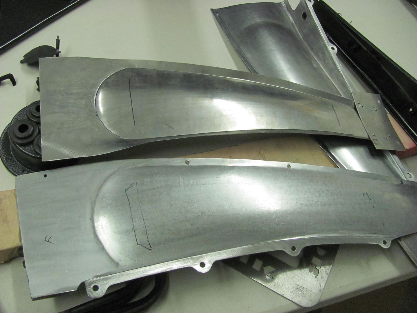
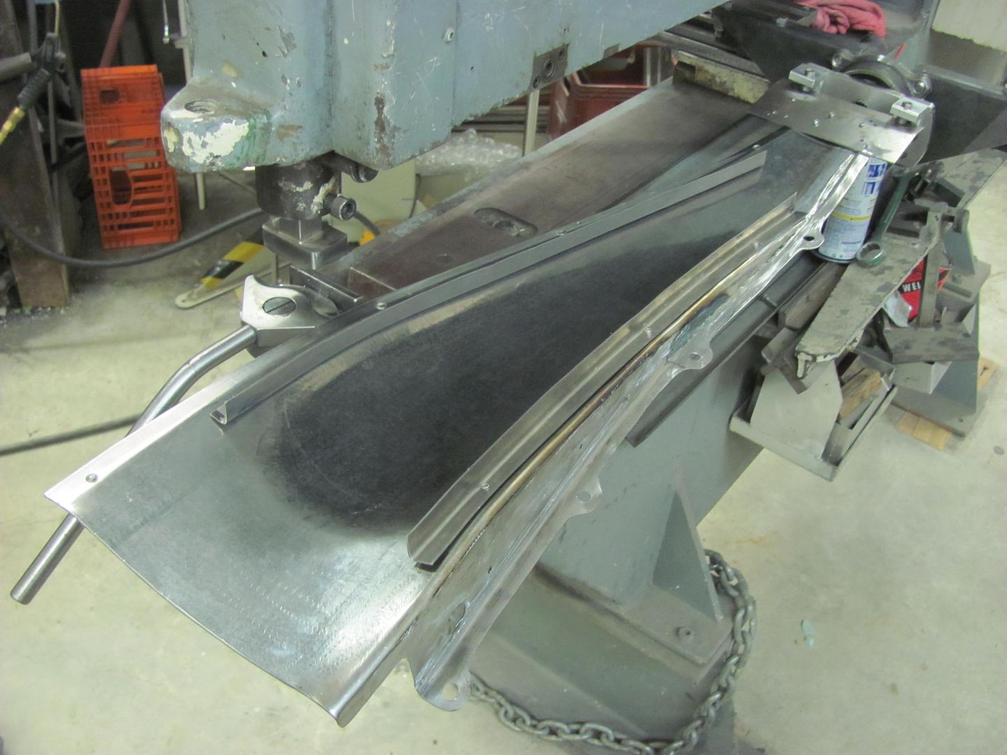
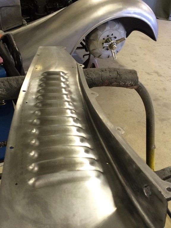
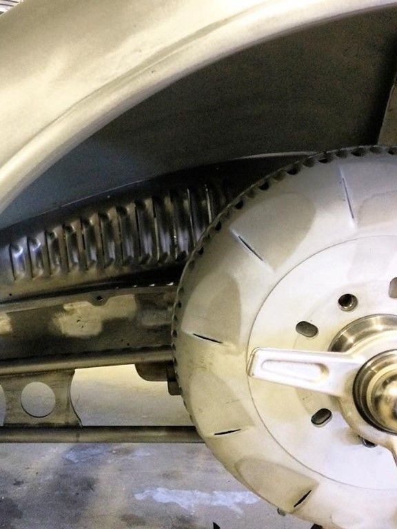
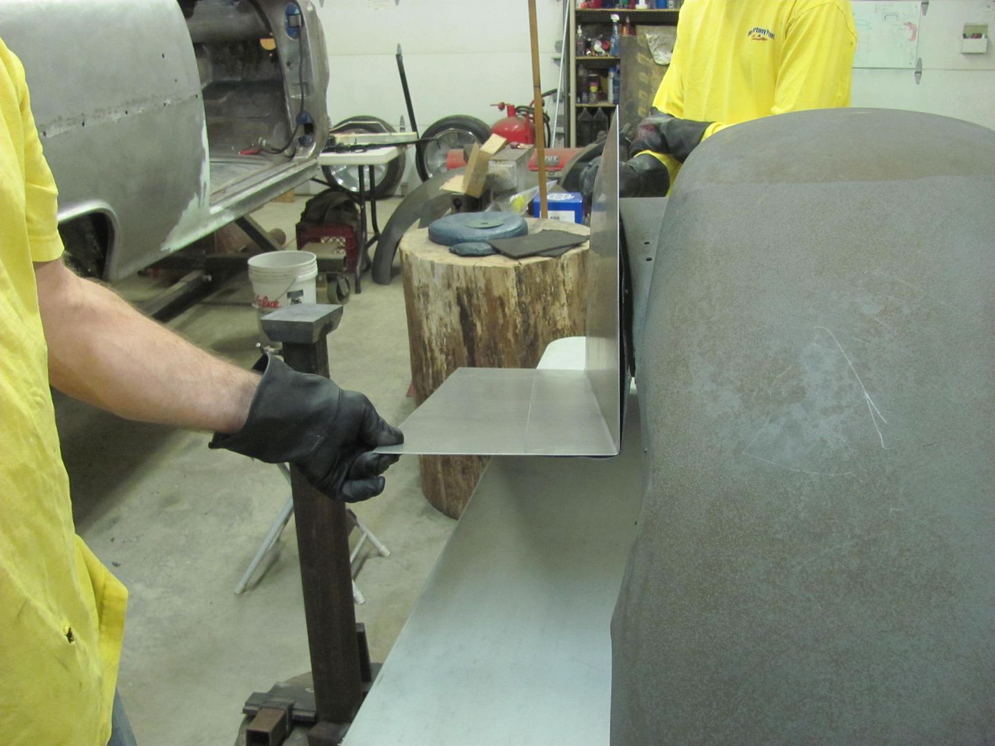
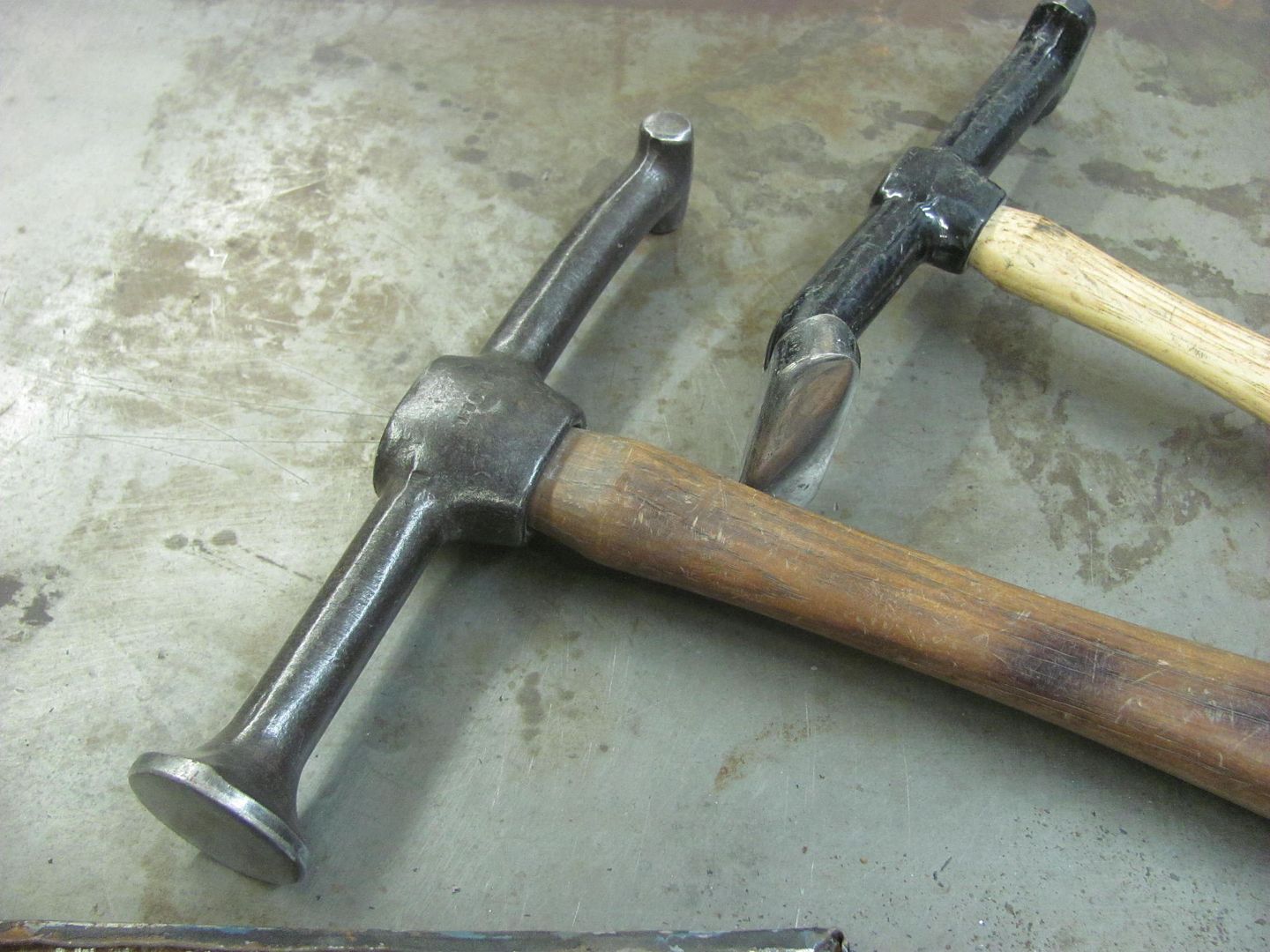
Worked on some louvers tonight, wanted to get some practice pieces done to see how well our "theory" might fare.


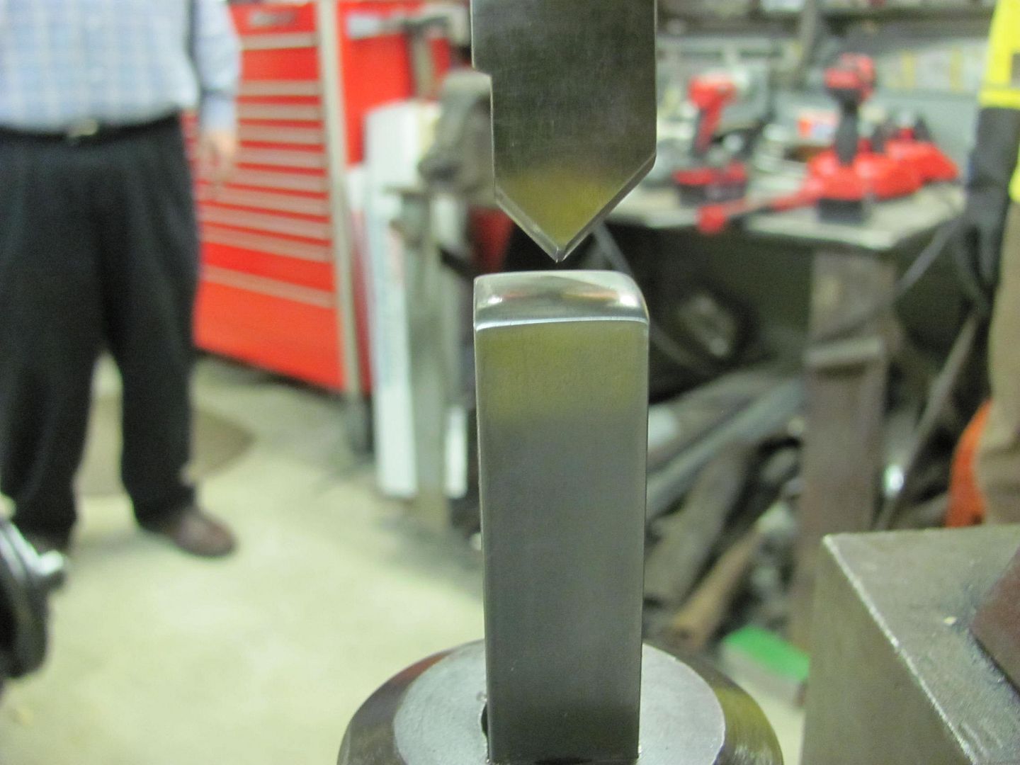
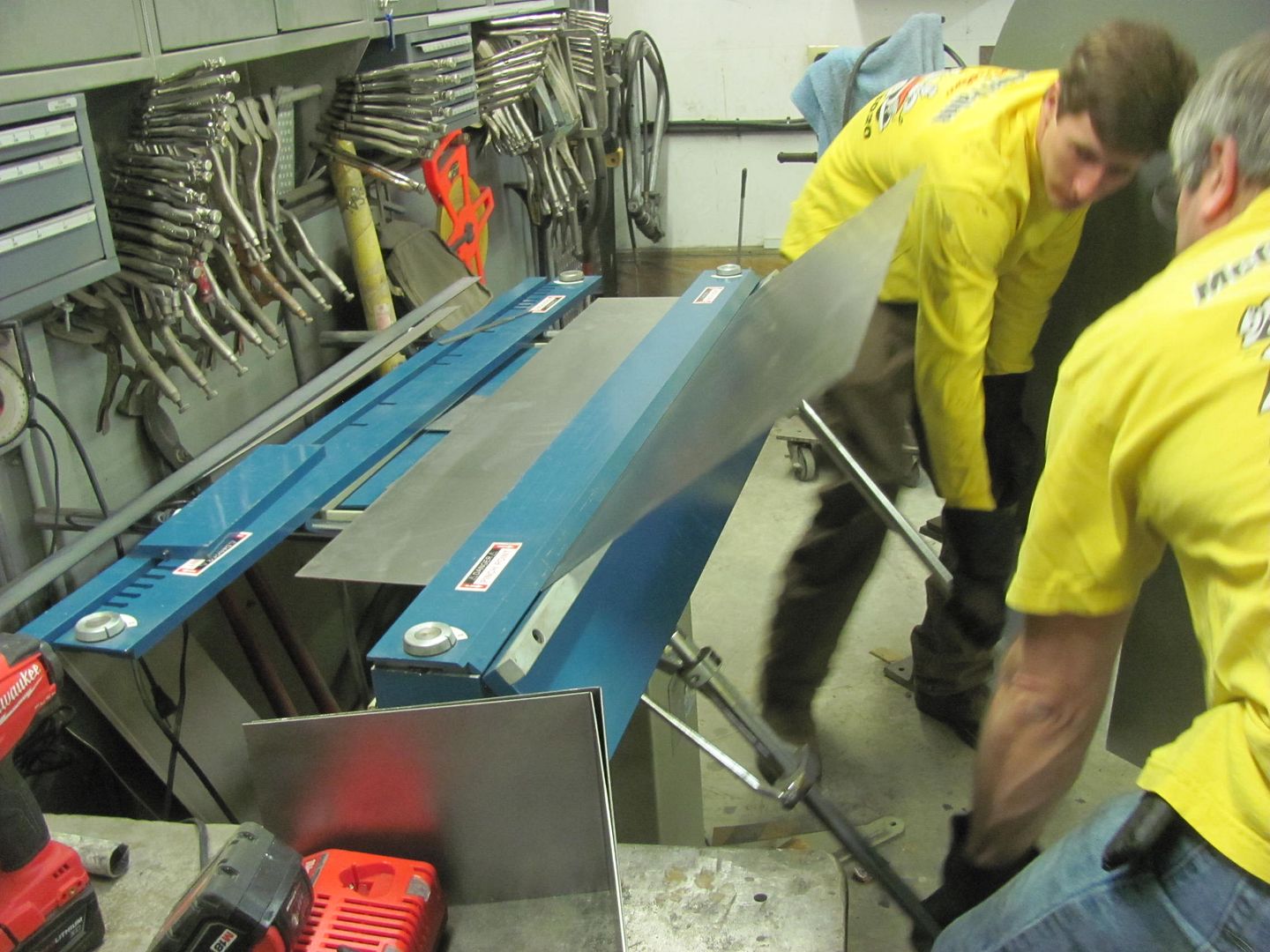
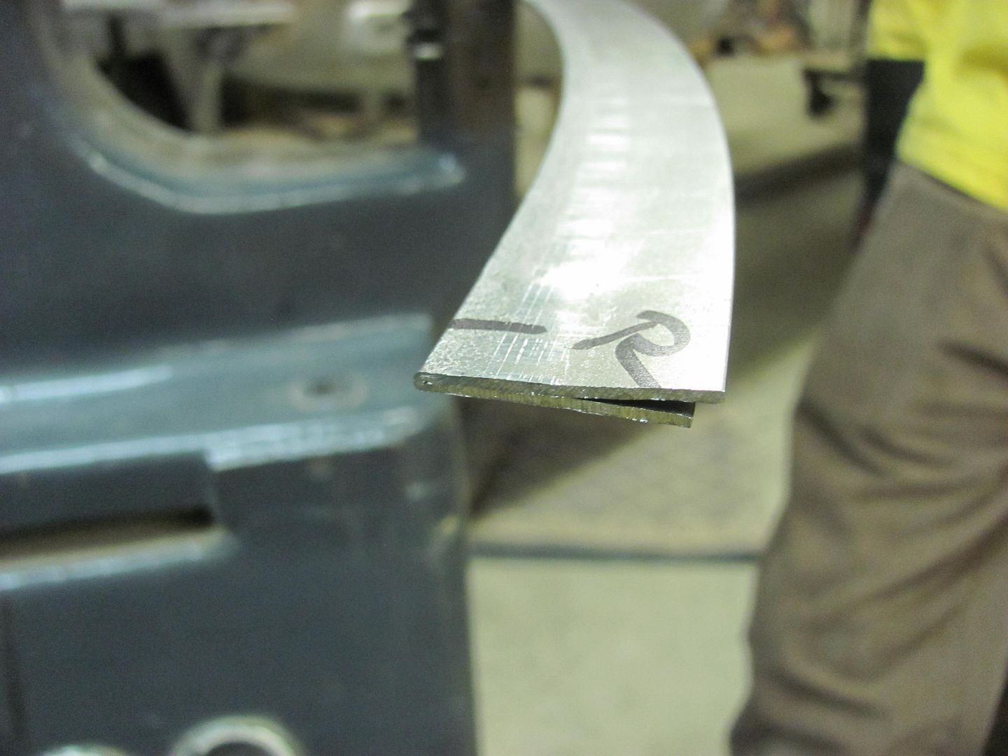
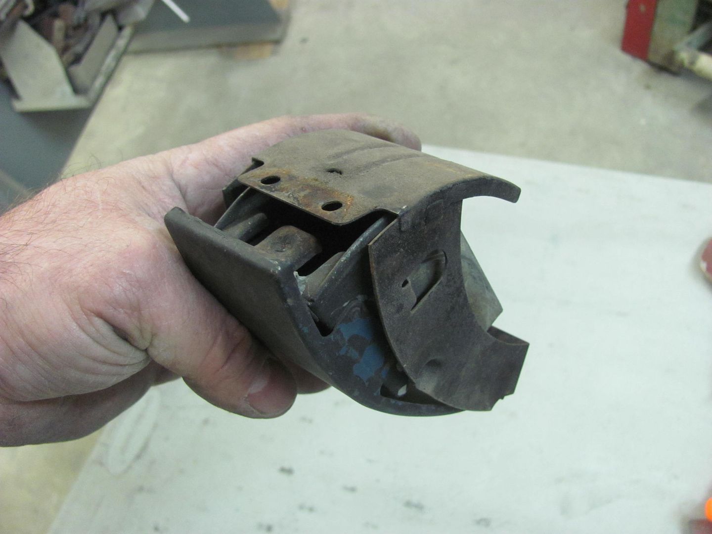
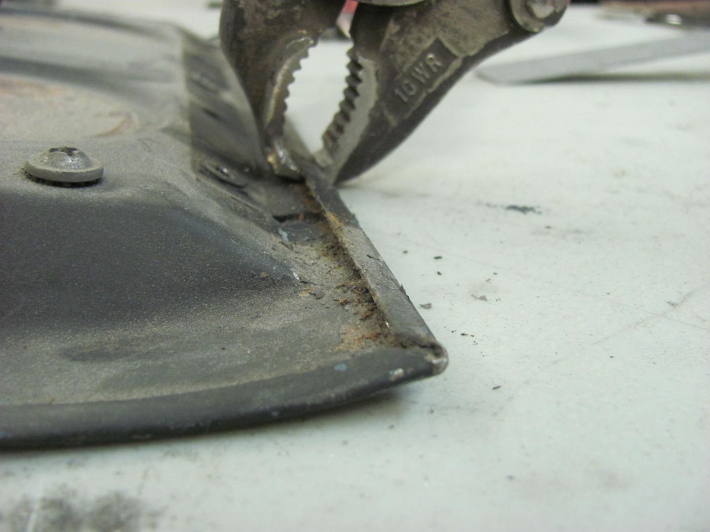
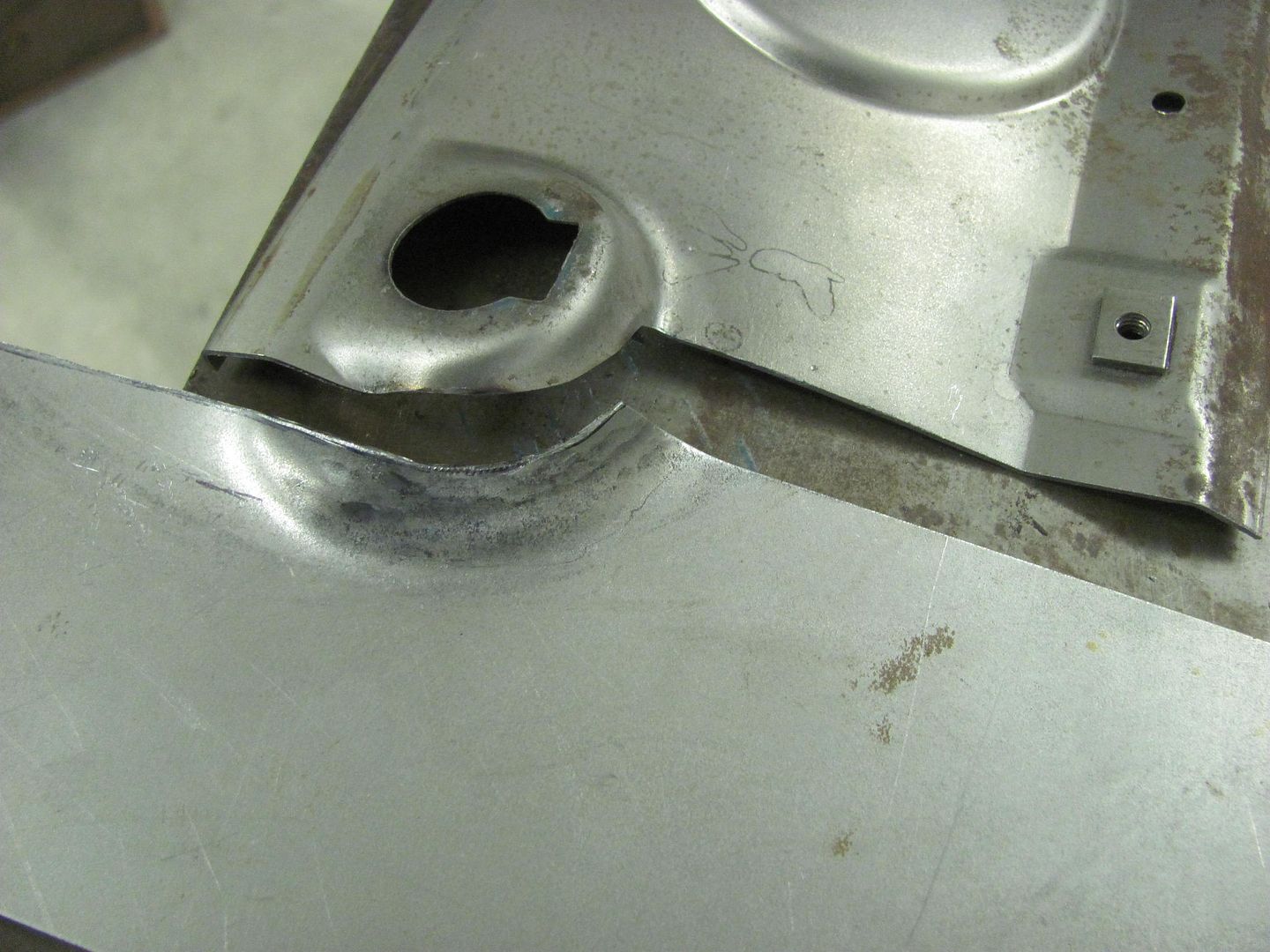
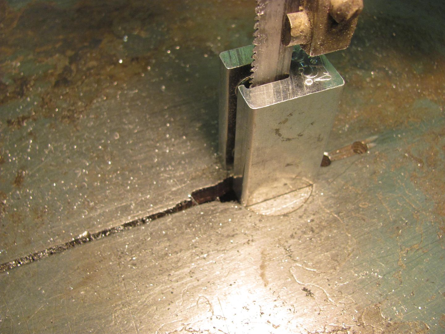
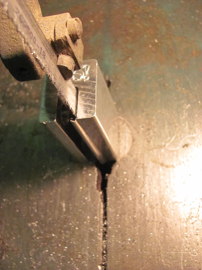
Kyle cutting an inside lip off the clamp before cutting it in half..


Picture%204196.jpg


Picture%204197.jpg


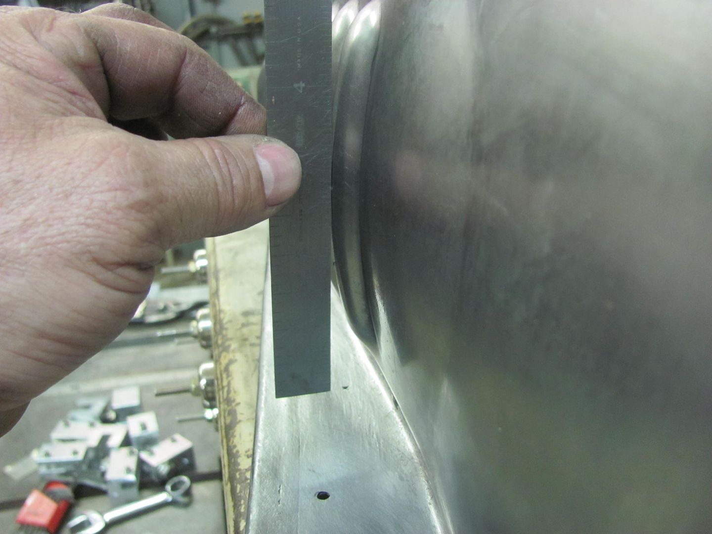
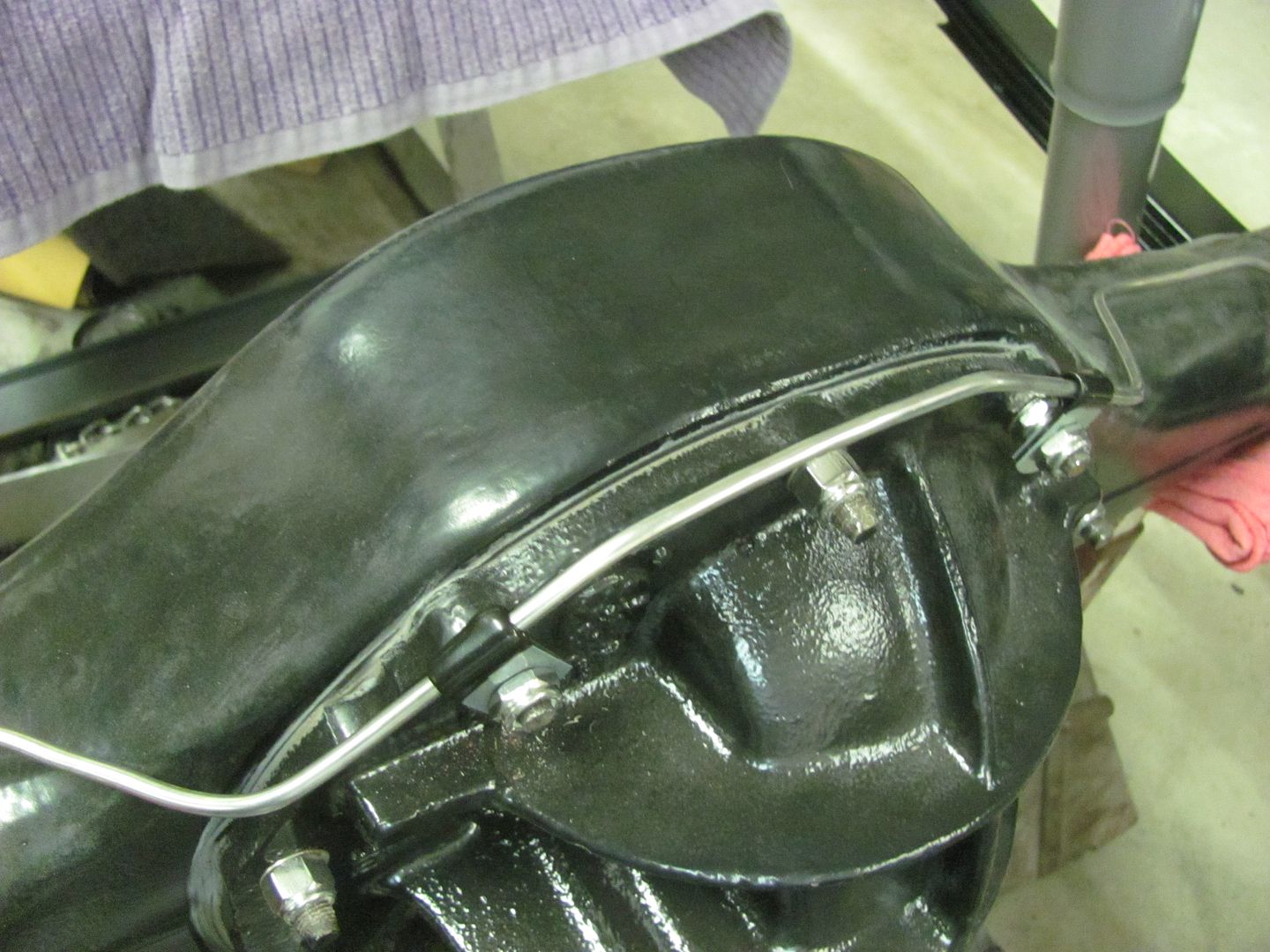
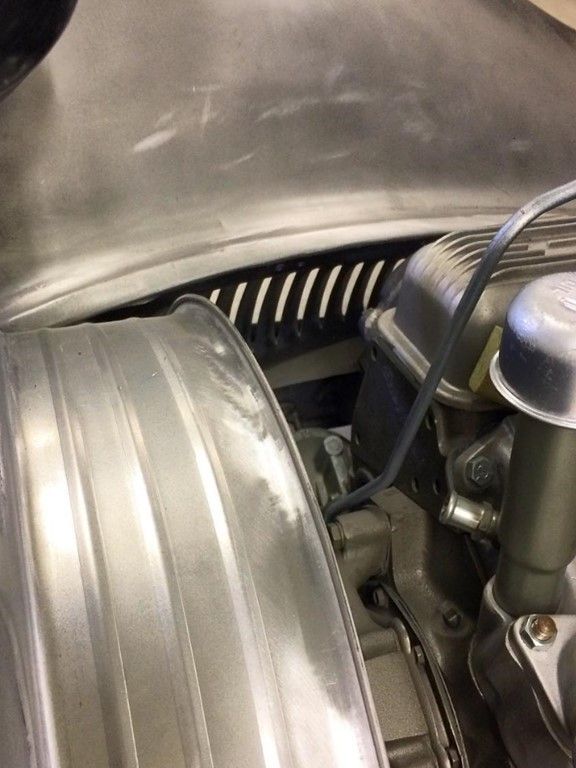
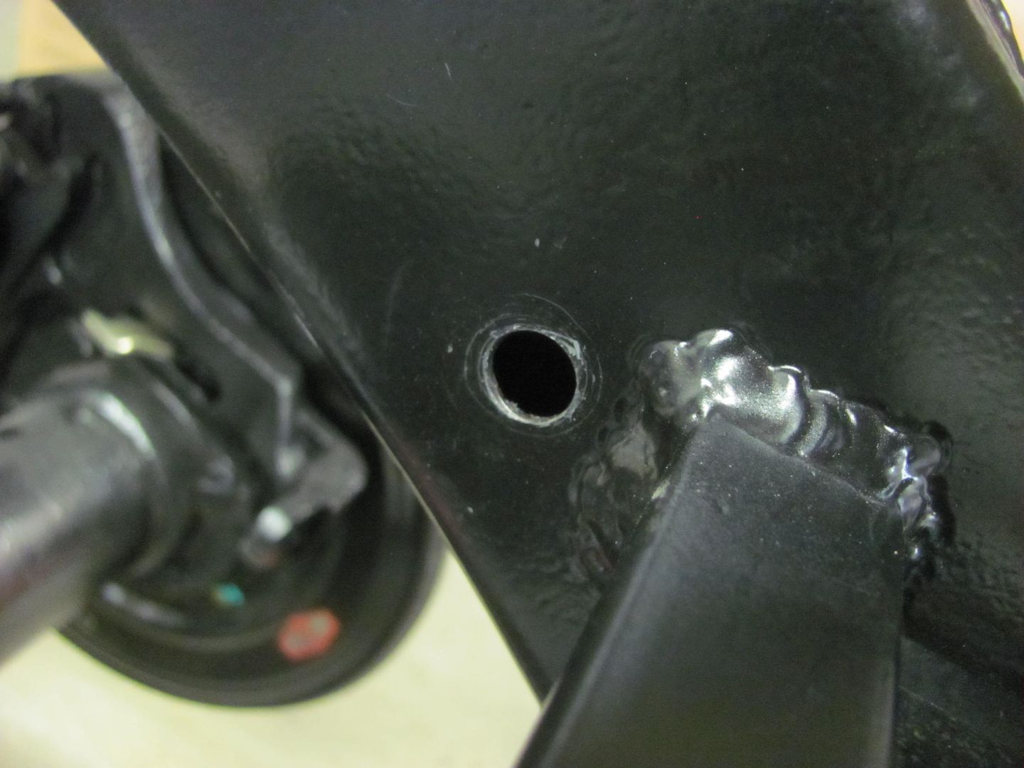
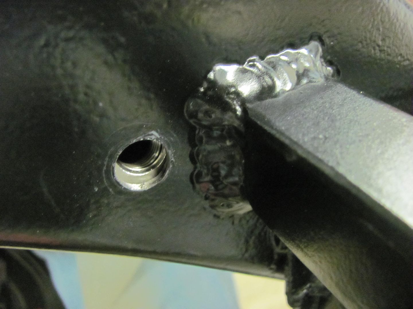
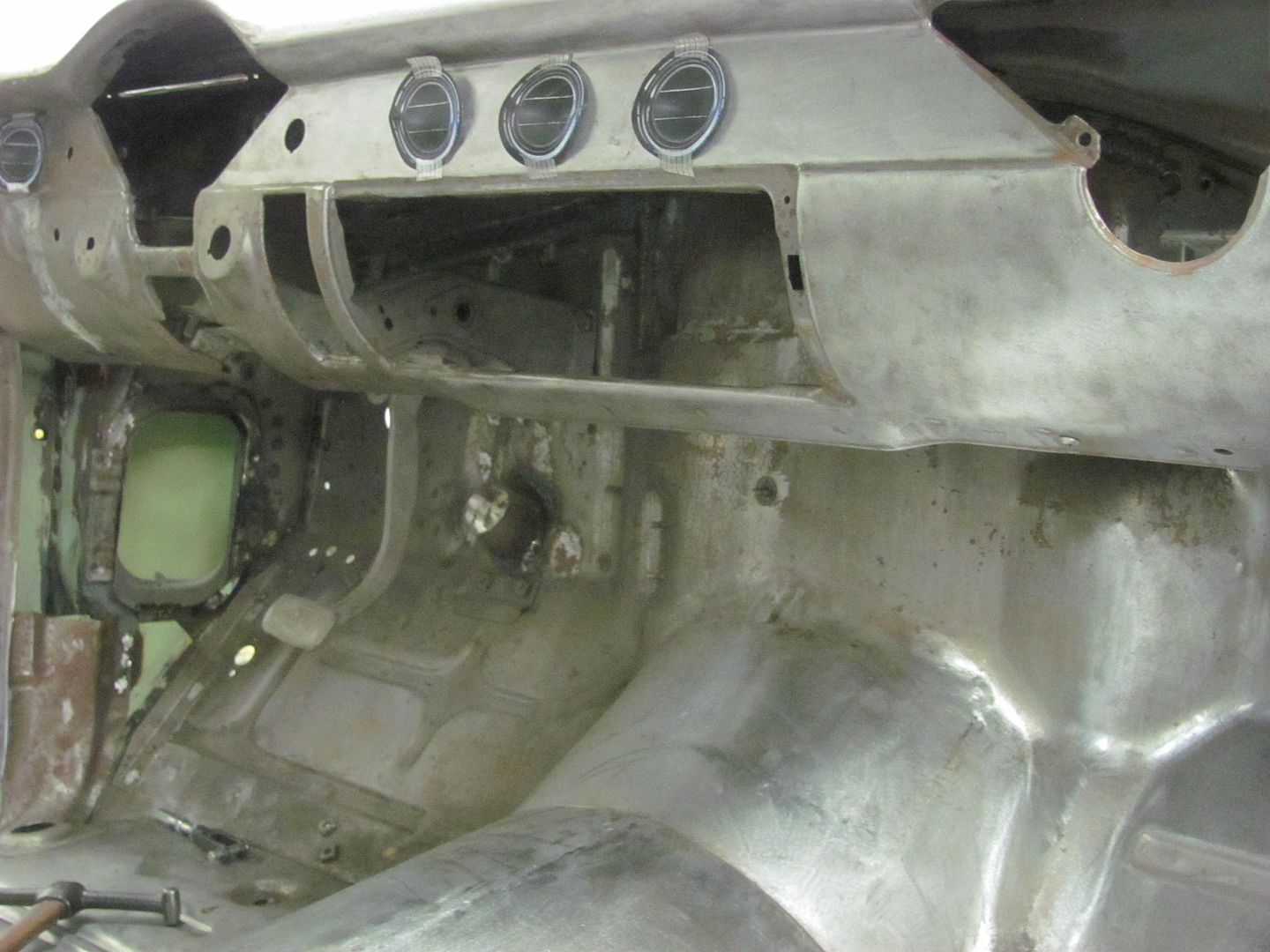
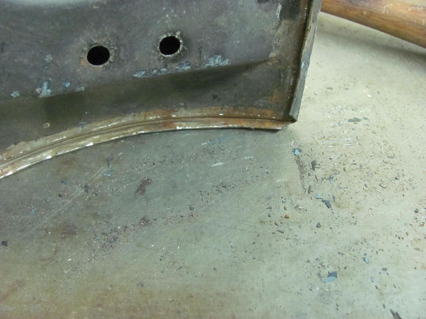
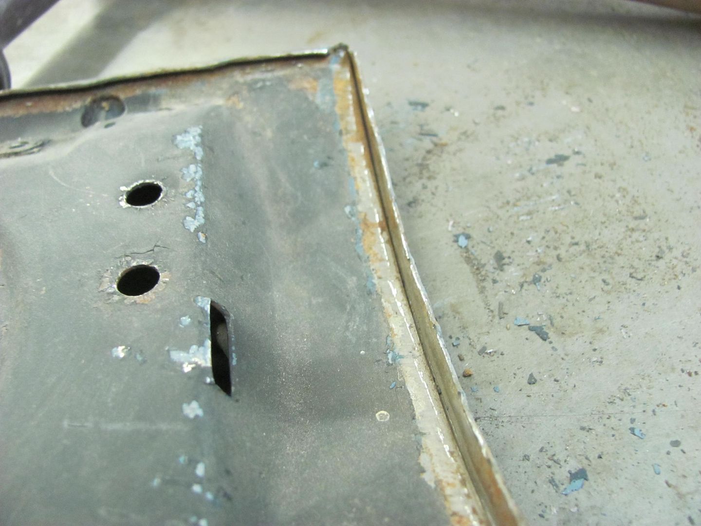
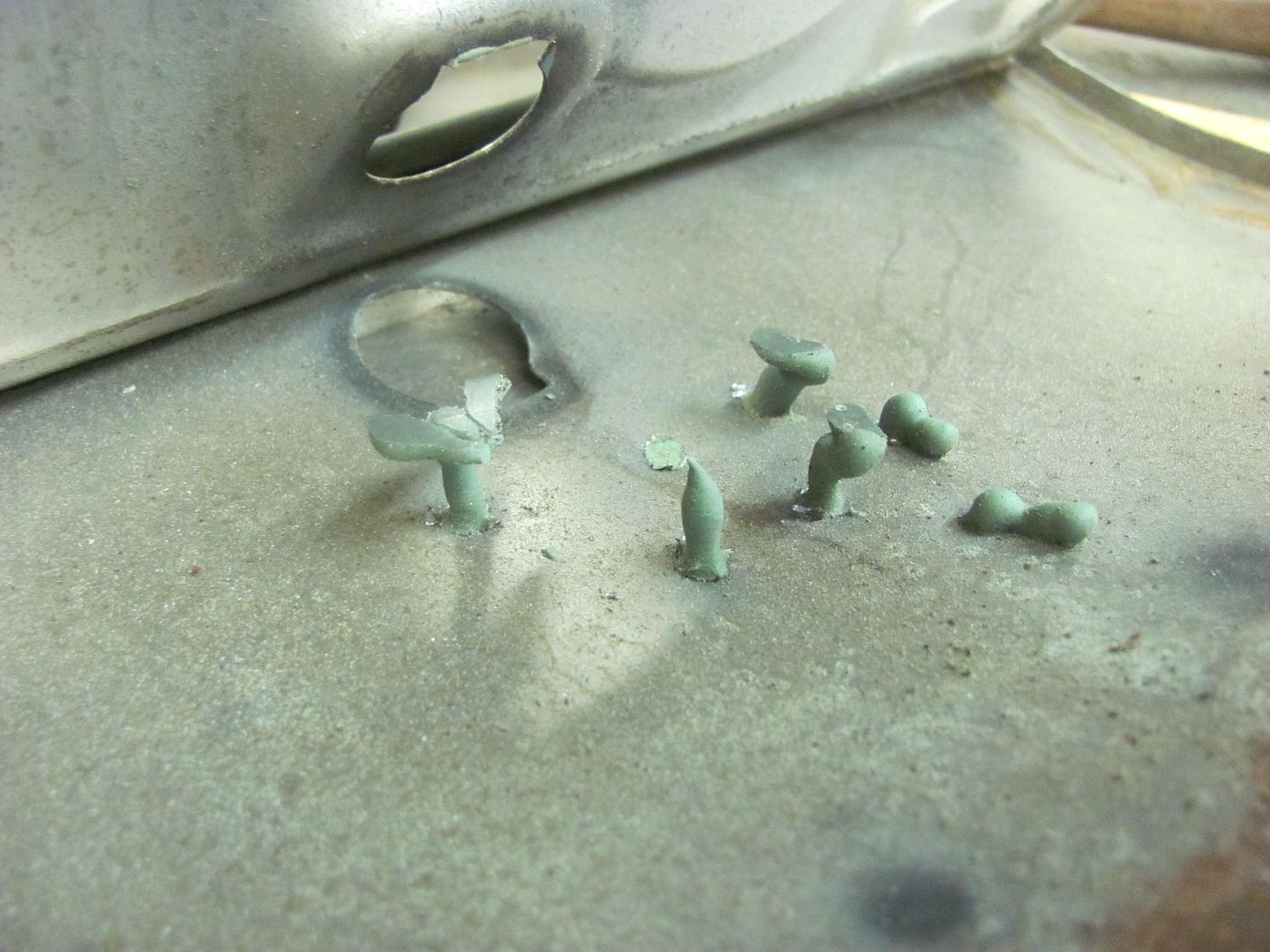
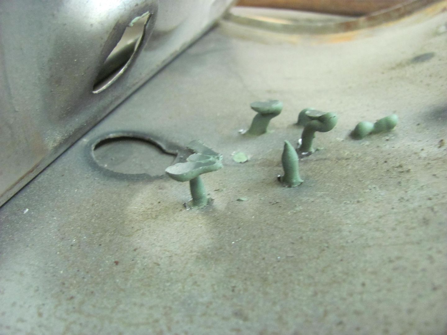
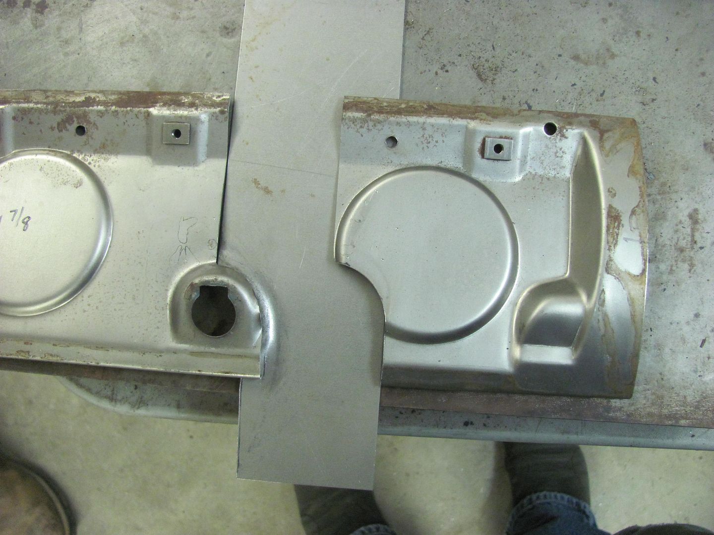
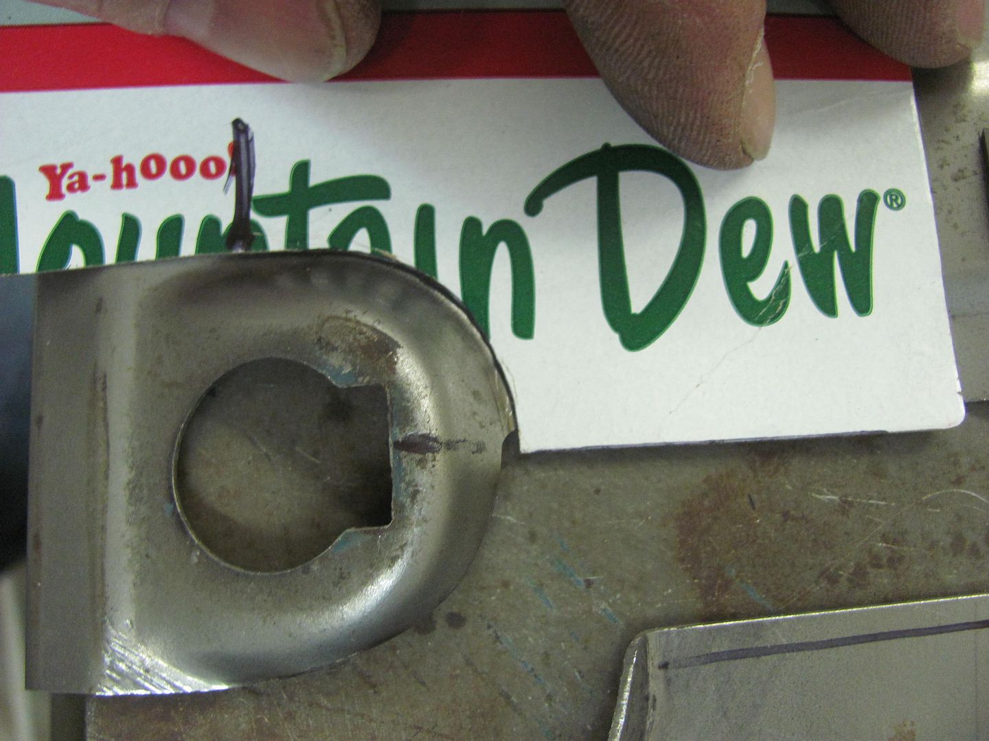
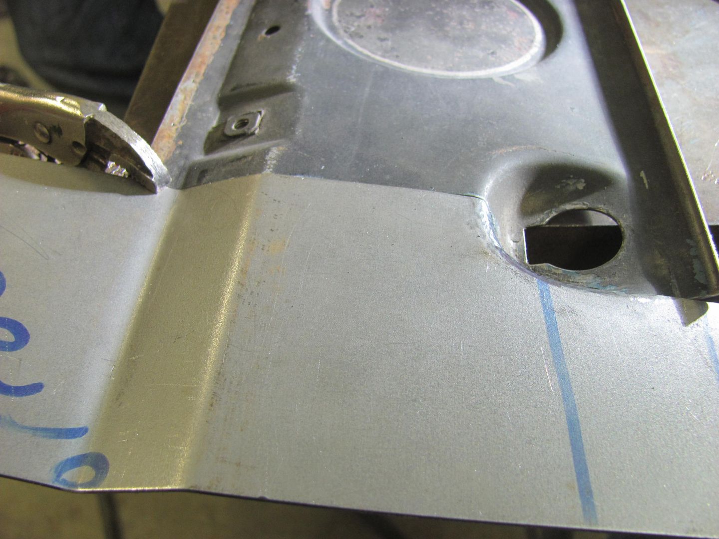
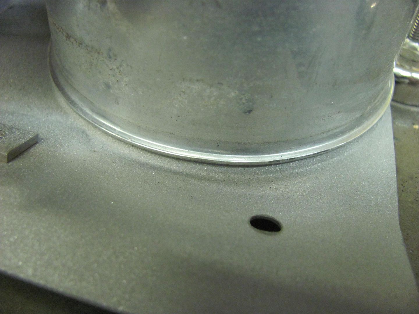
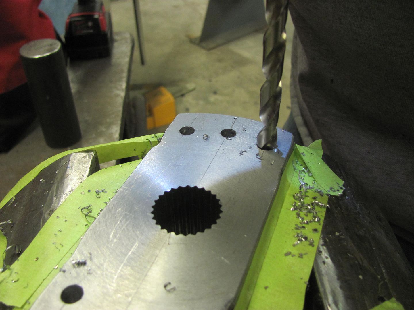
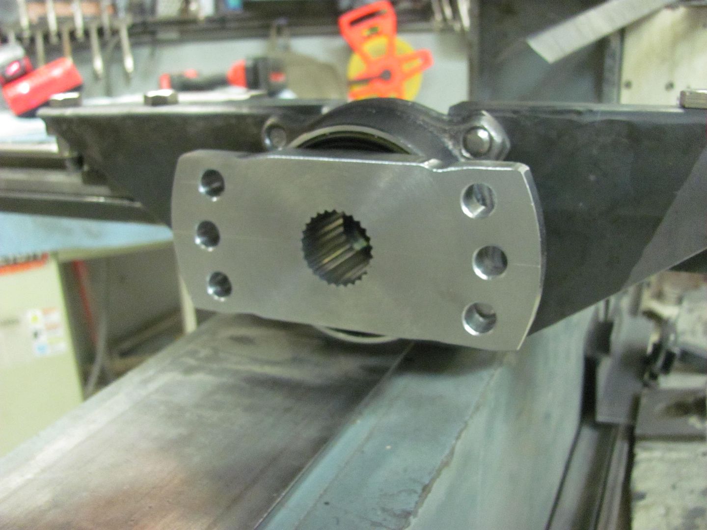
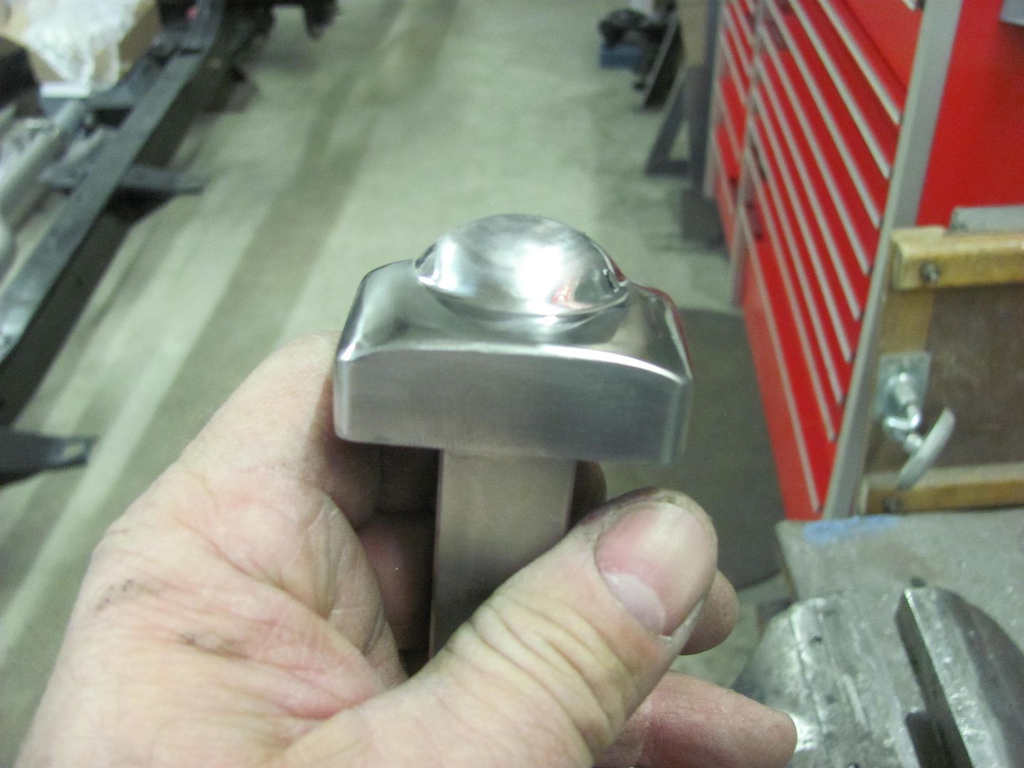
Meanwhile I got the holes (and some spares for height adjustment) drilled in the wheel hub flange...
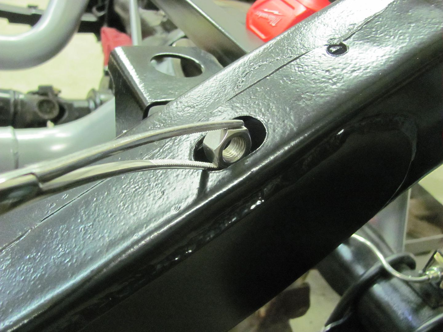
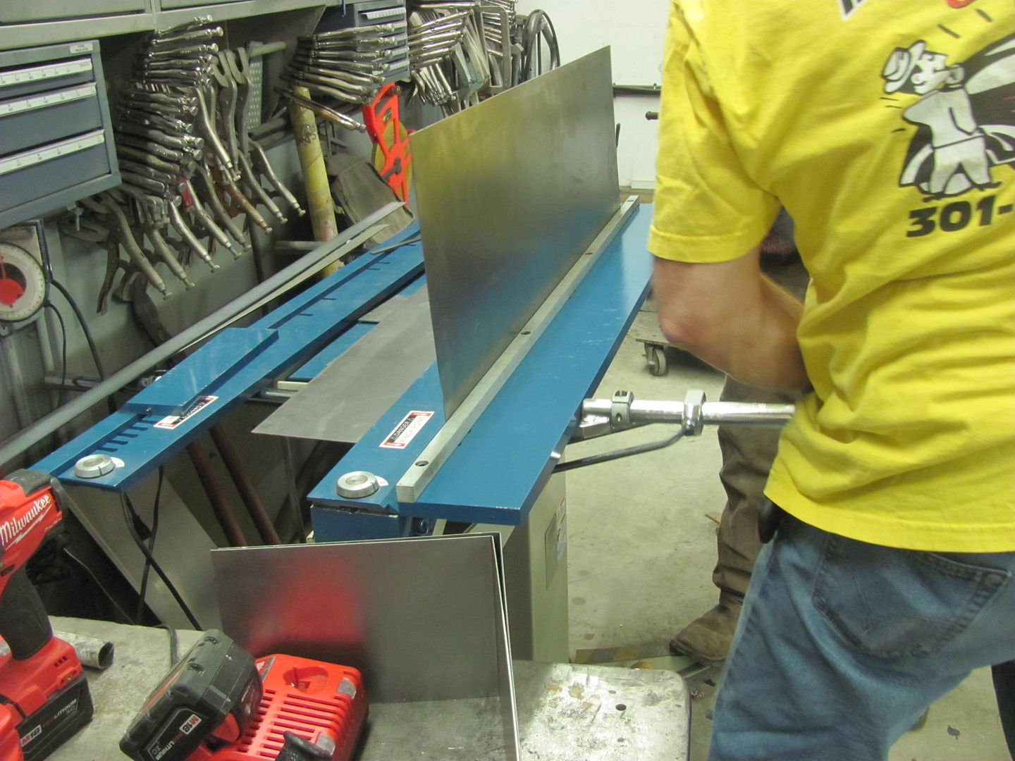
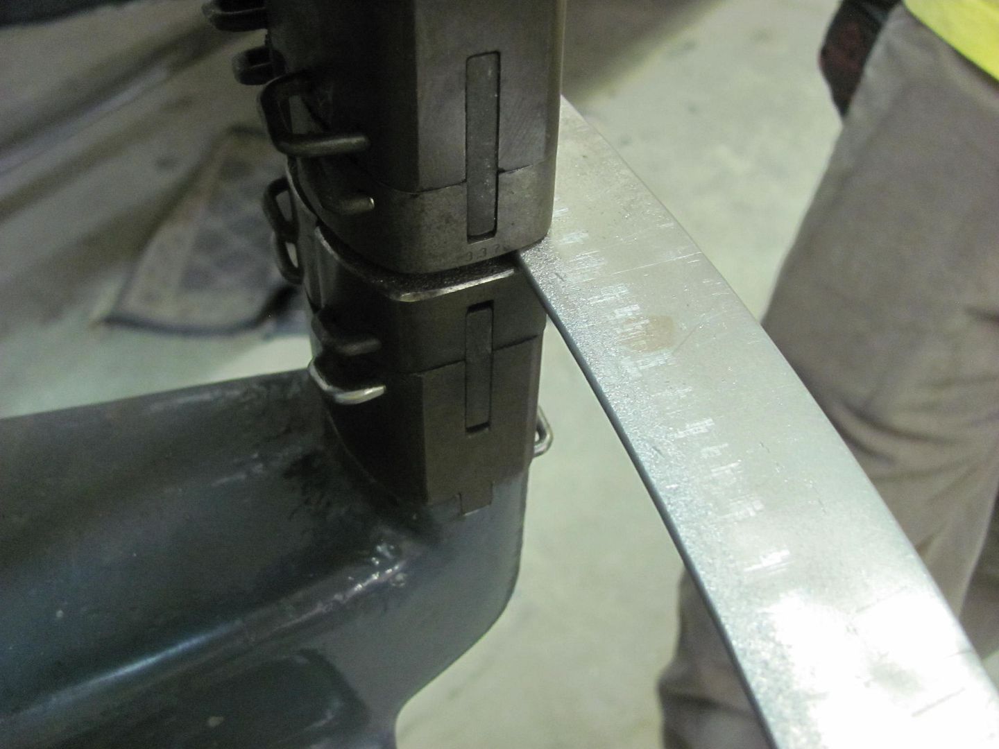
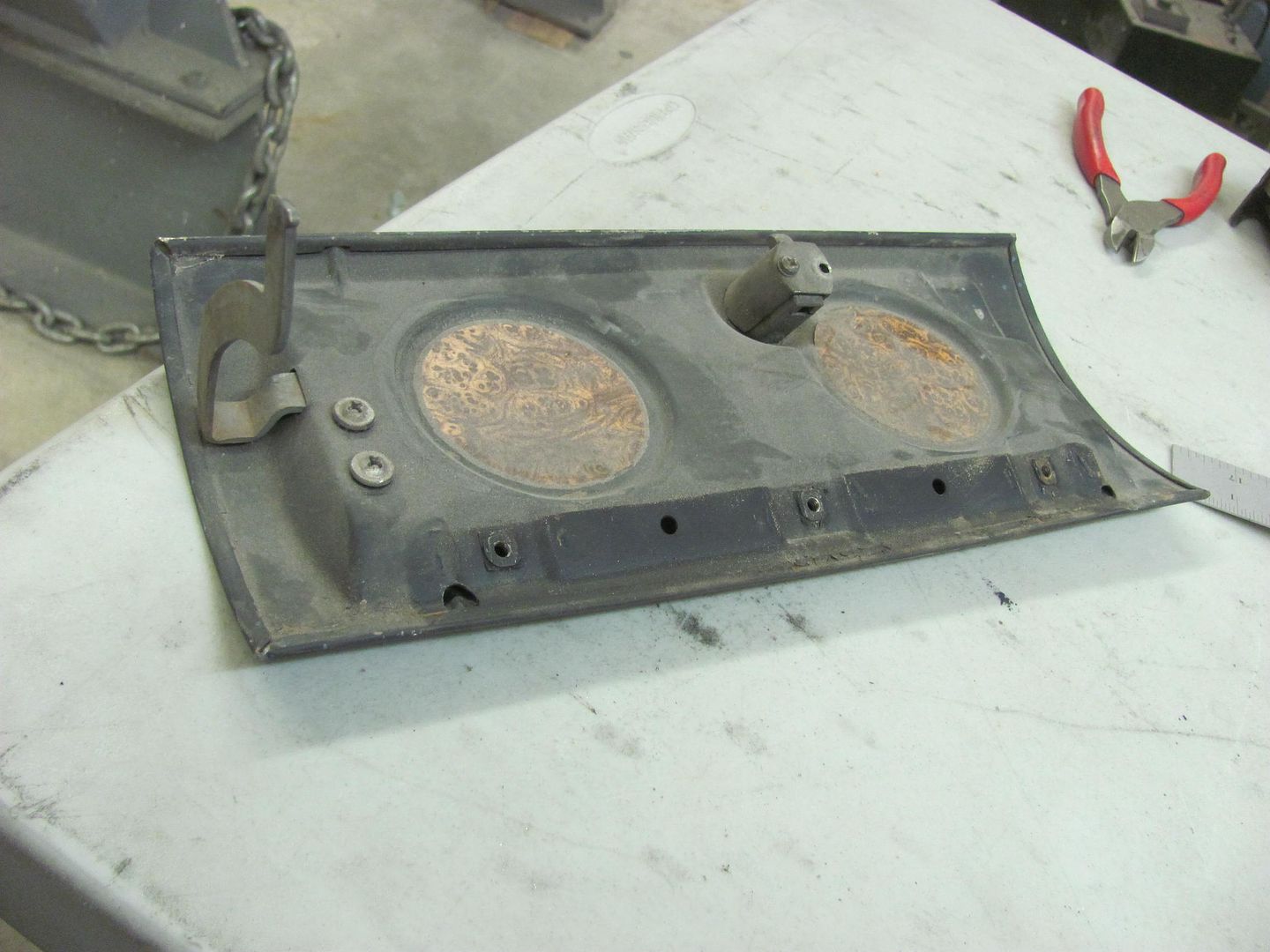
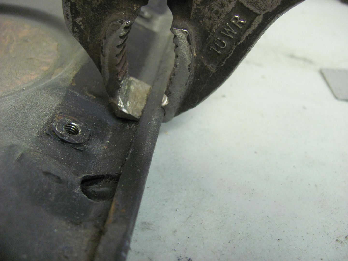
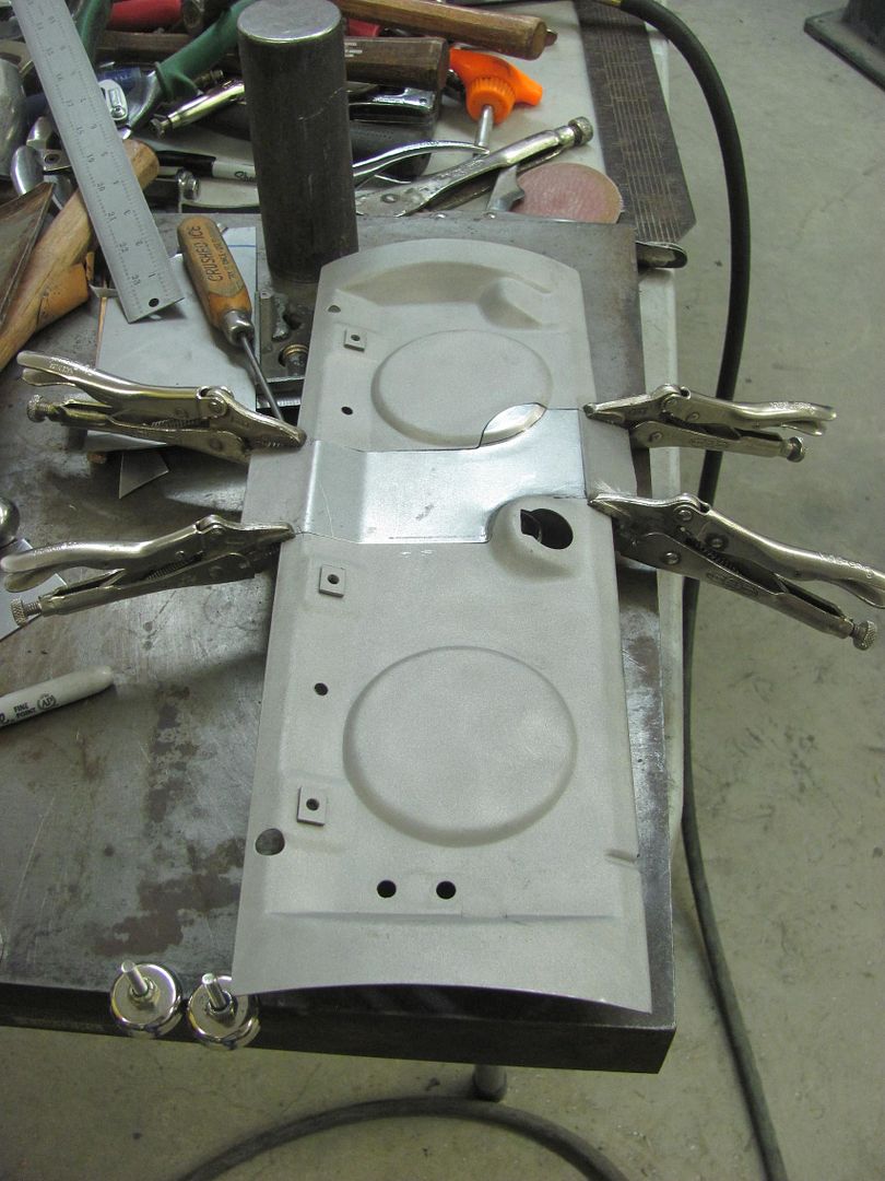
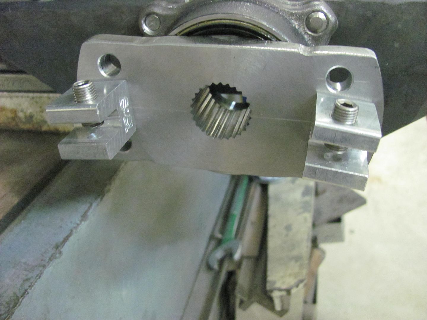
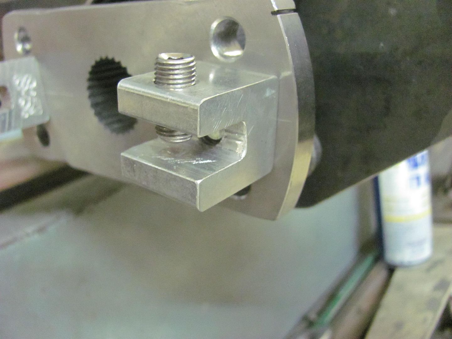
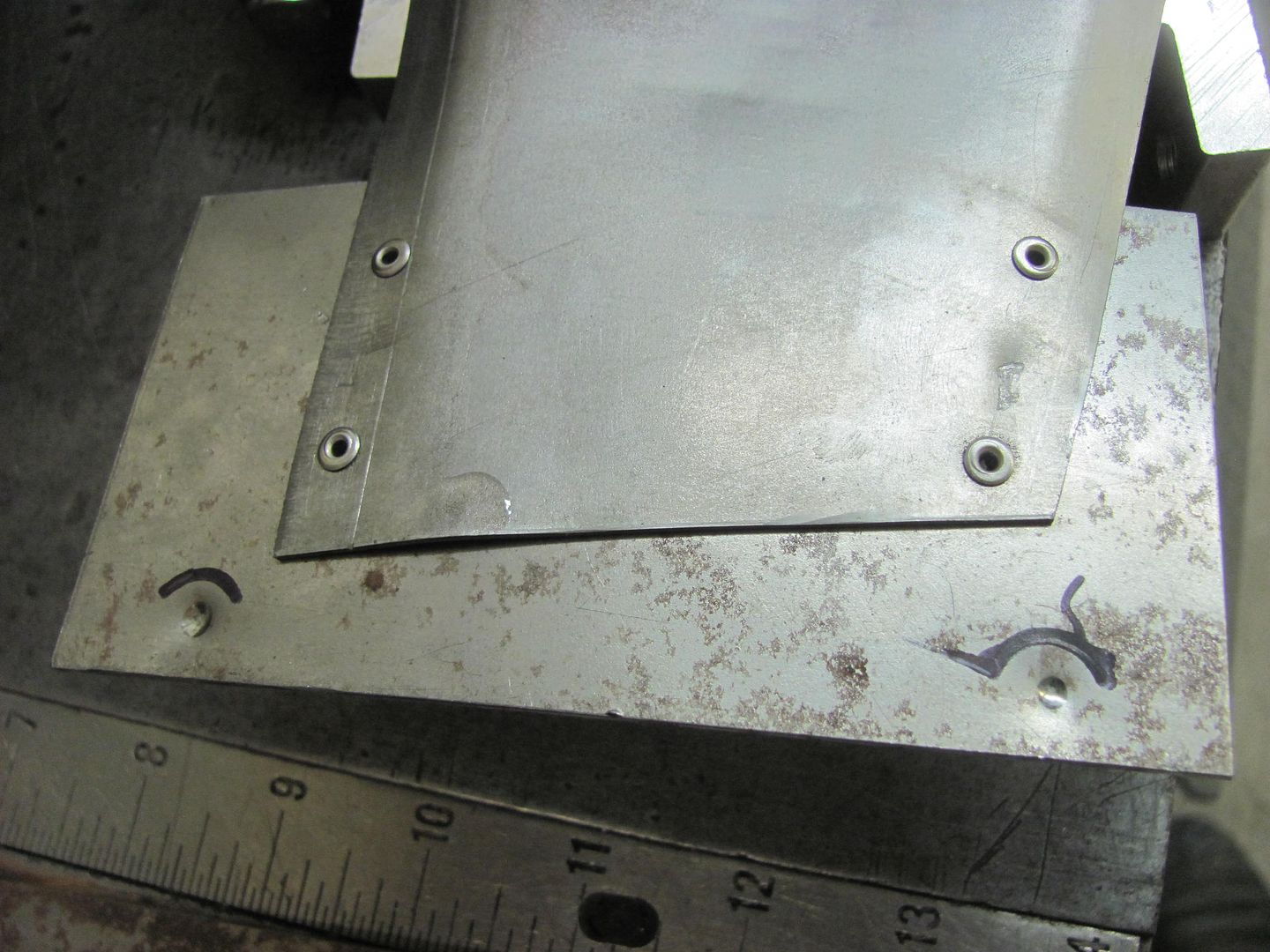

Picture%204198.jpg


Picture%204200.jpg


Clamps added...


Picture%204212.jpg


Picture%204213.jpg


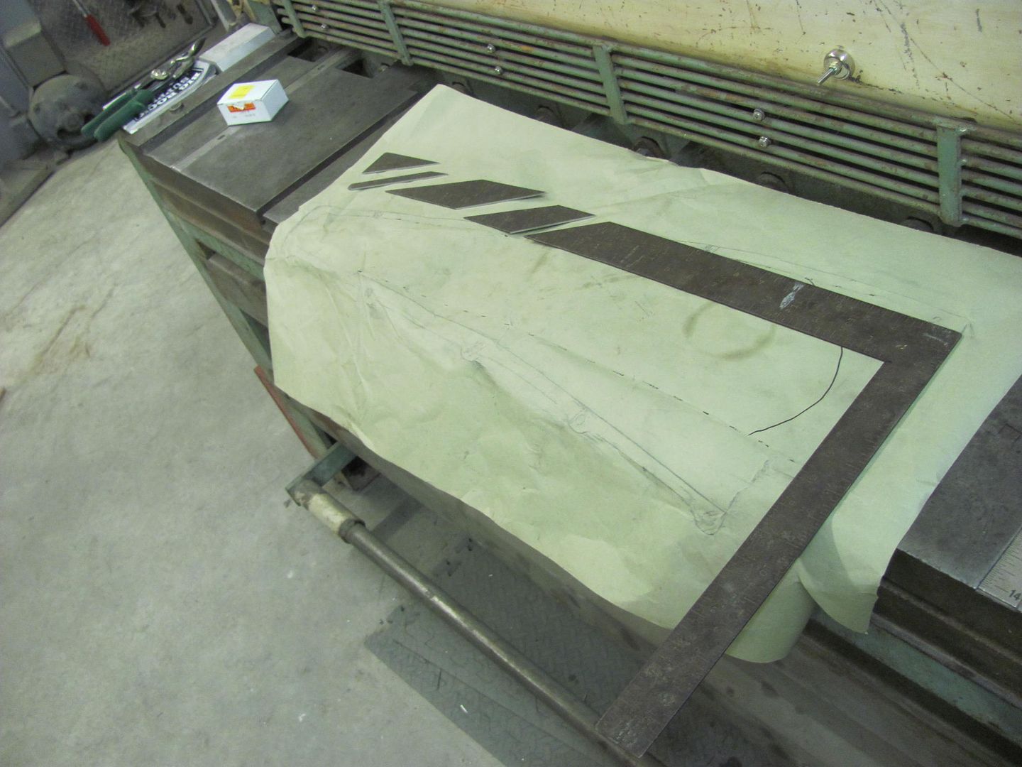
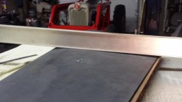
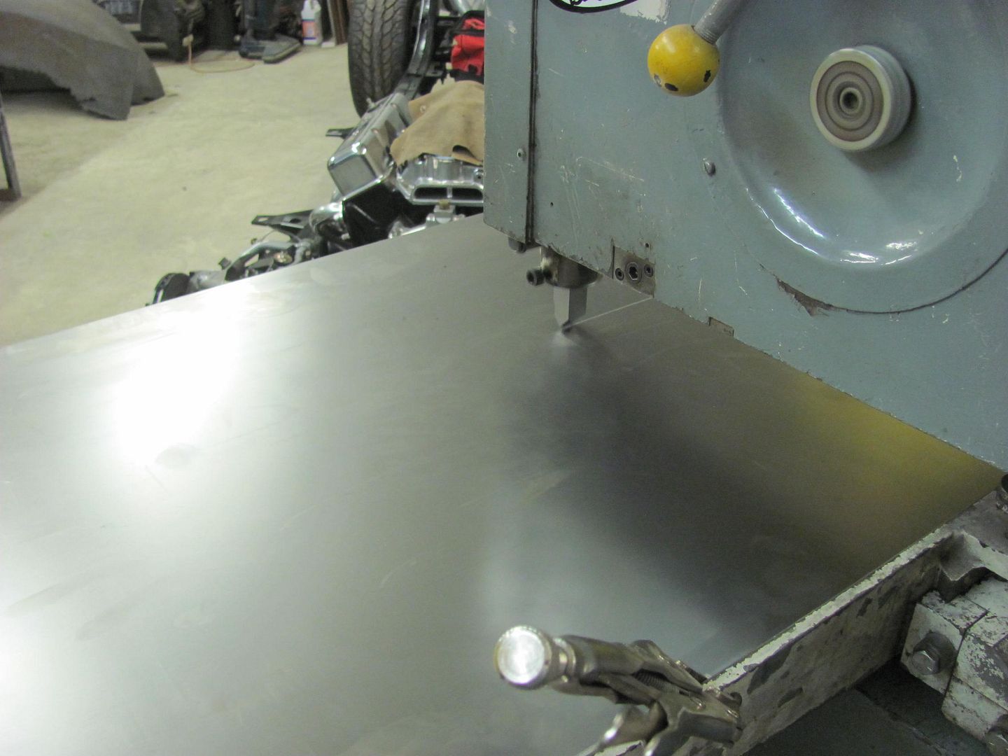
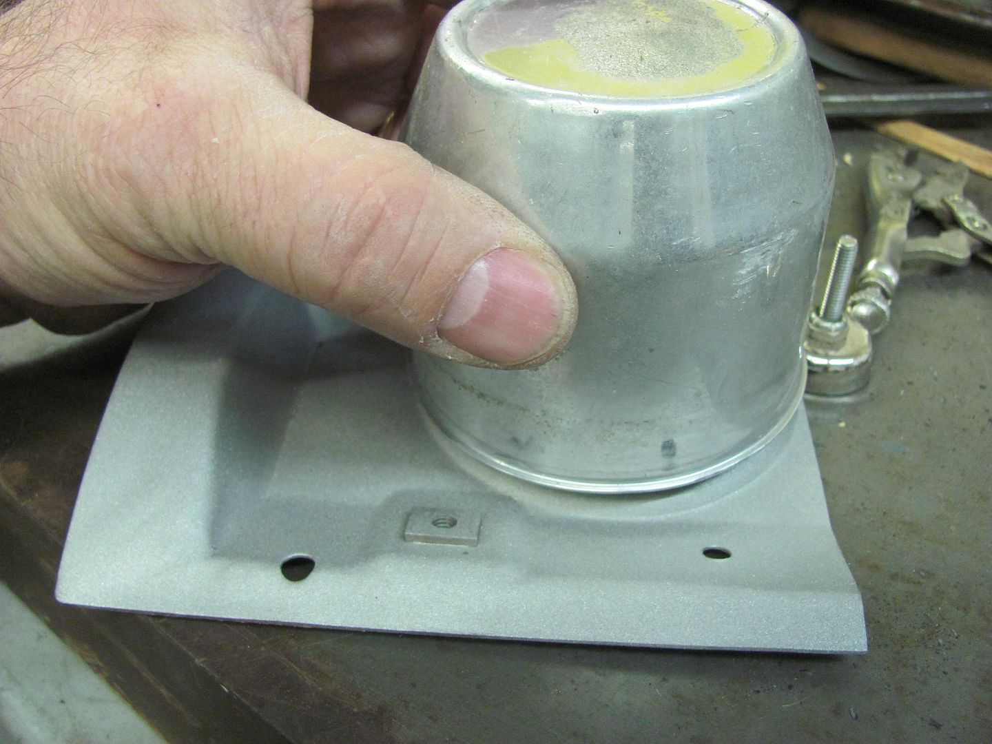
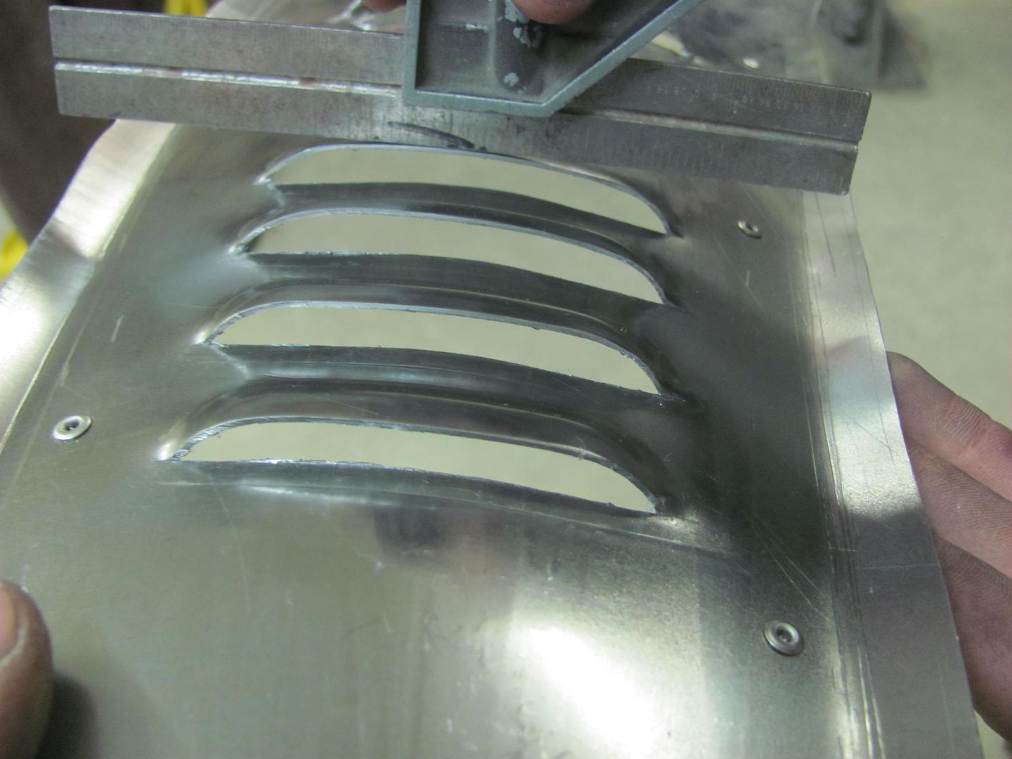
We used a "squaring plate" to align the panel for louver angle..


Picture%204214.jpg


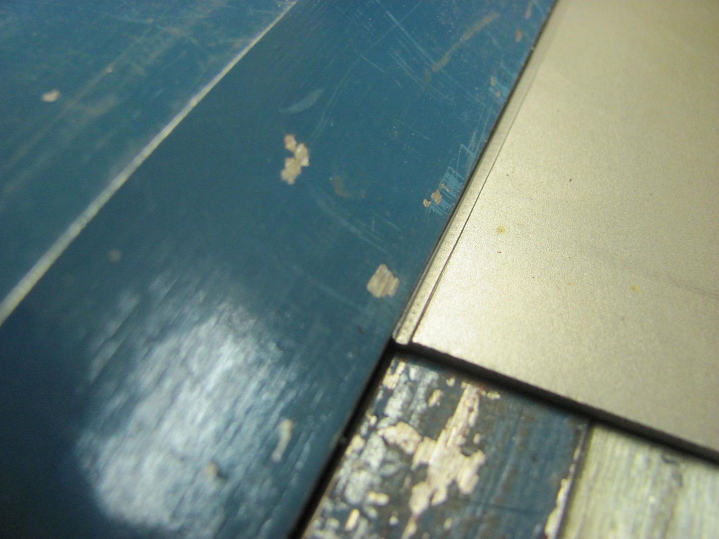
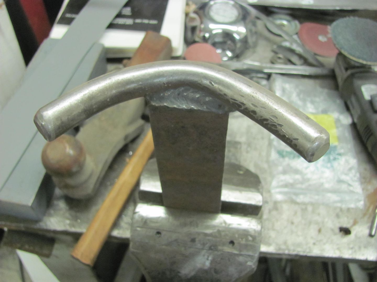
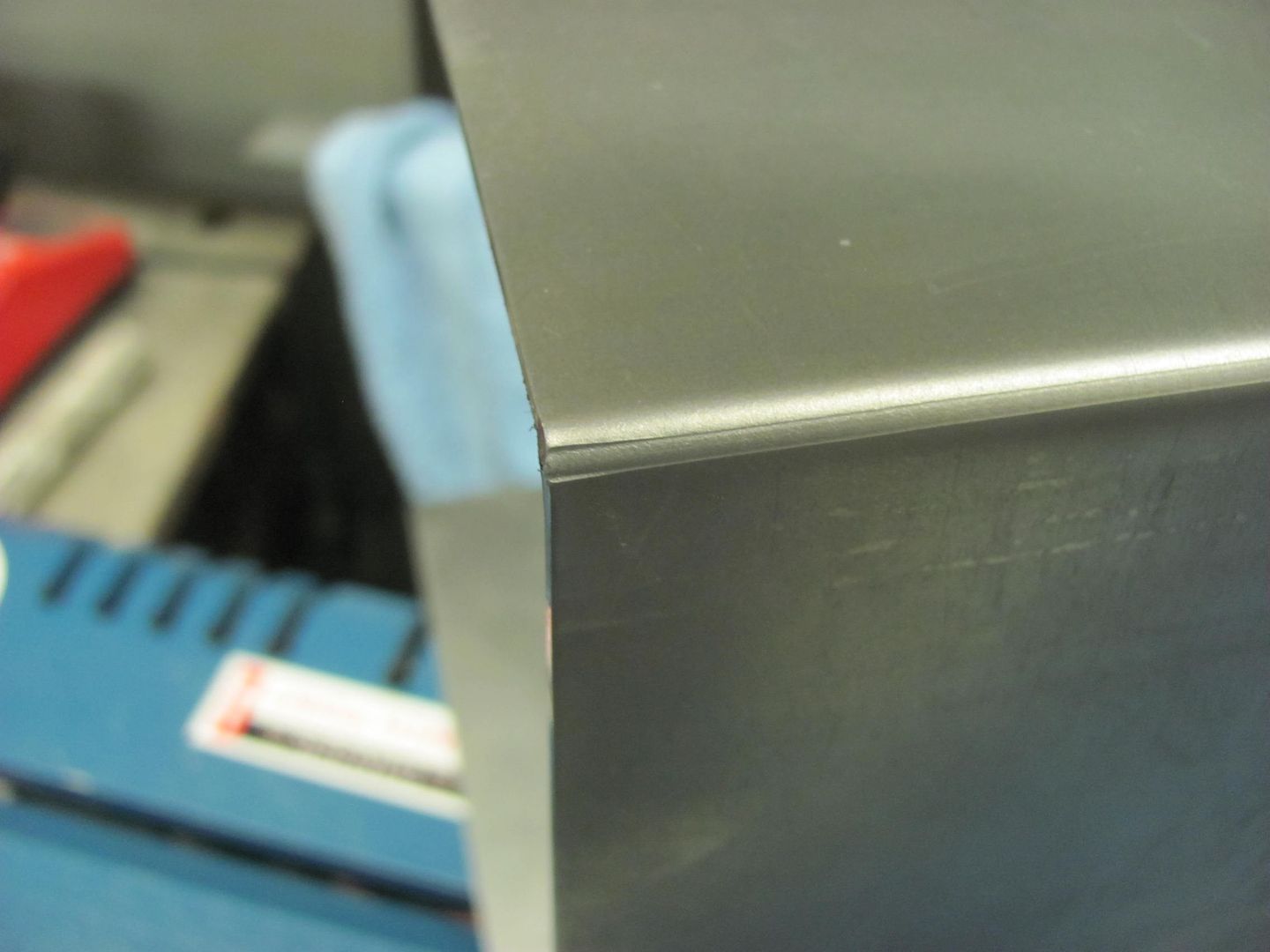
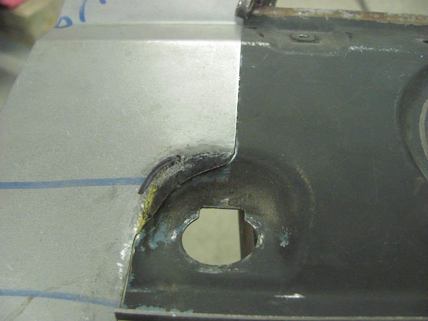
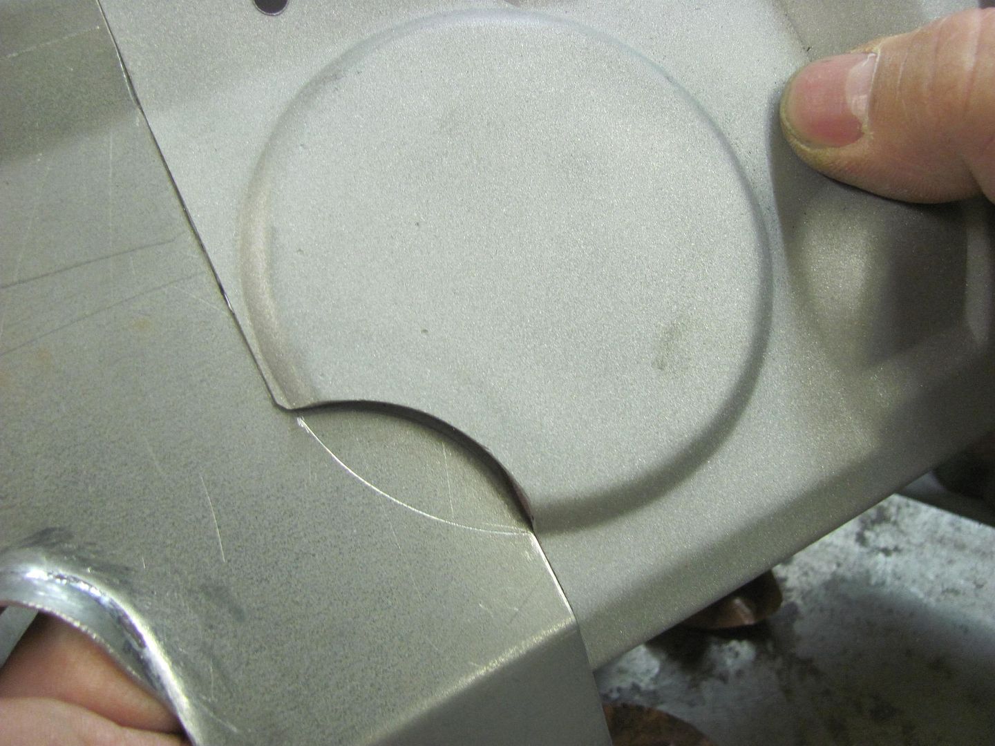
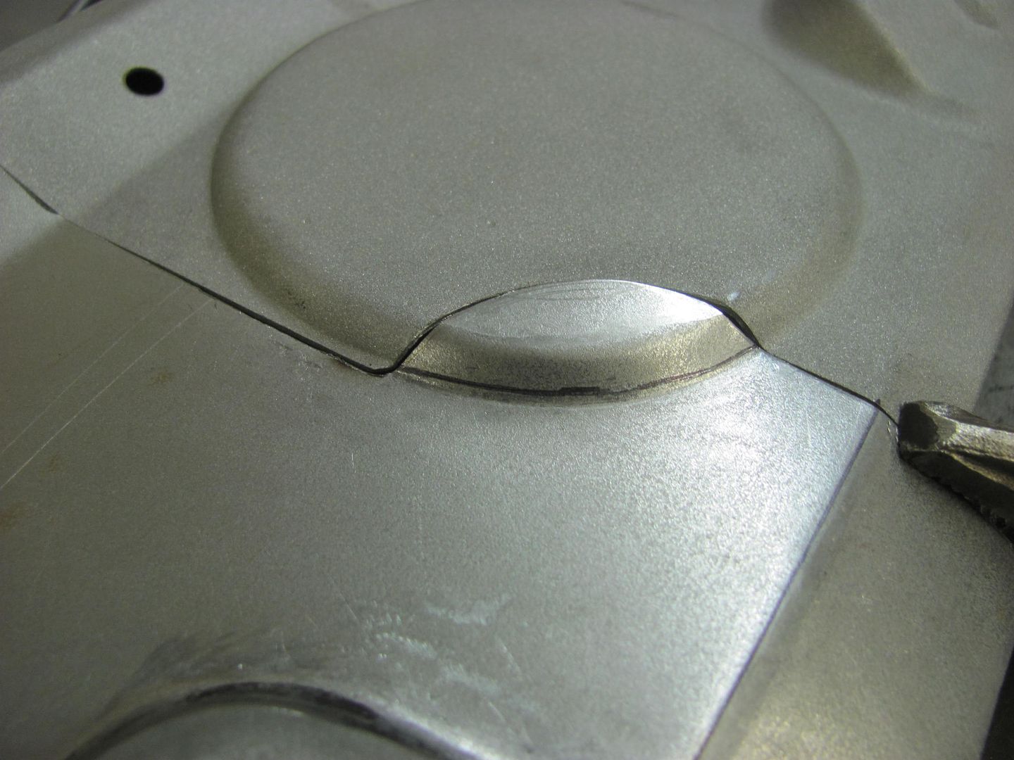
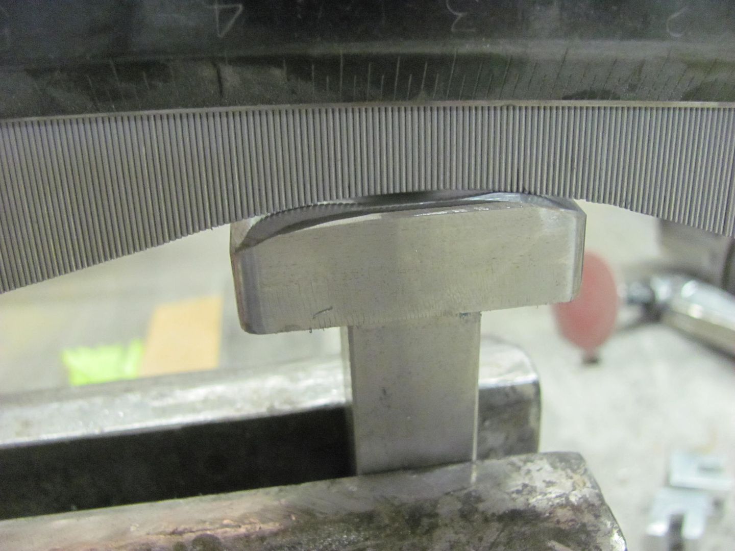
The punch needed some relieving to insure the corners didn't hit the inside radius of the panel...


Picture%204201.jpg


Picture%204202.jpg


Picture%204203.jpg


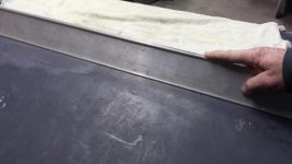
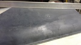
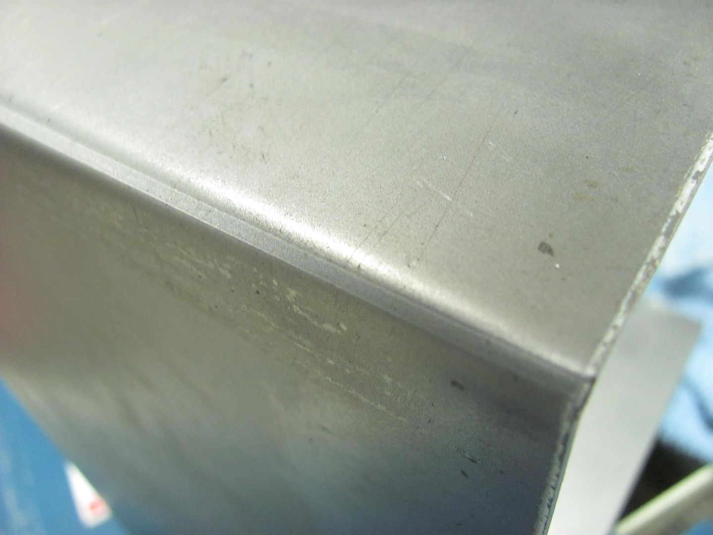
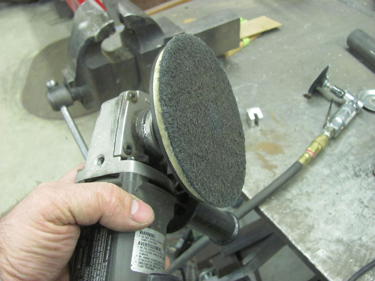
Cleaned up the grinder marks with a Scotchbrite pad..


Picture%204204.jpg


Picture%204205.jpg


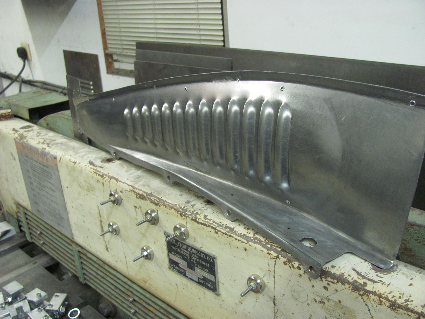
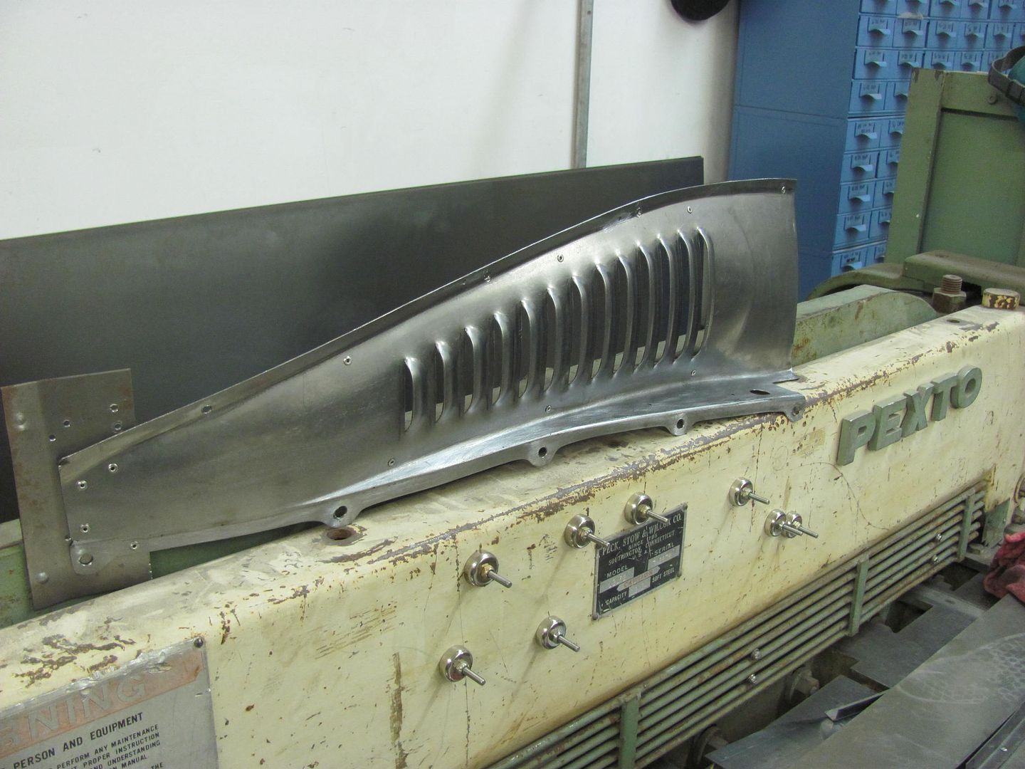
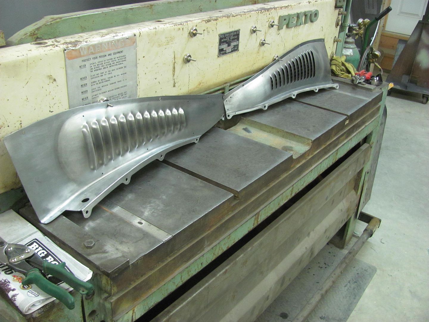
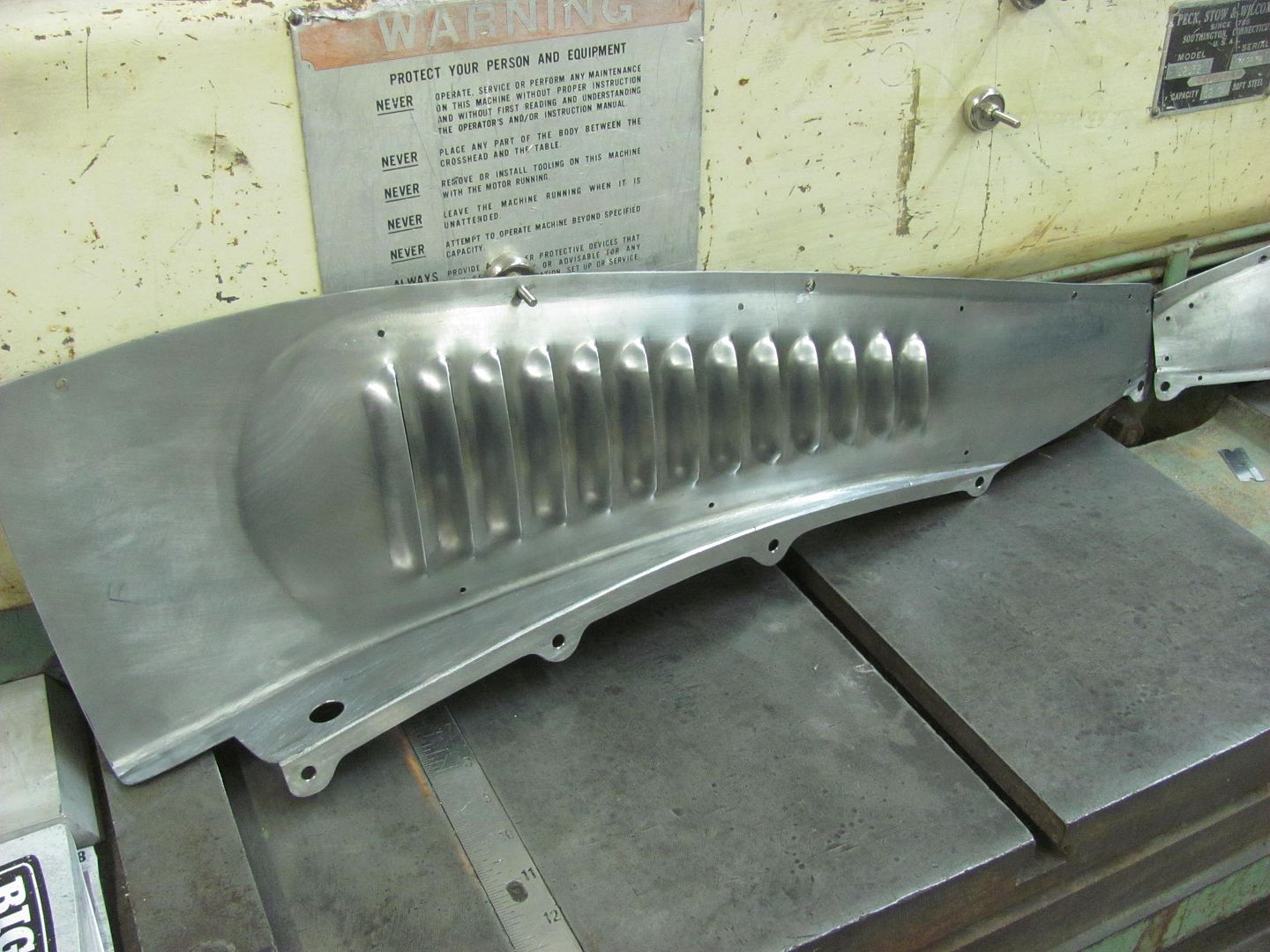
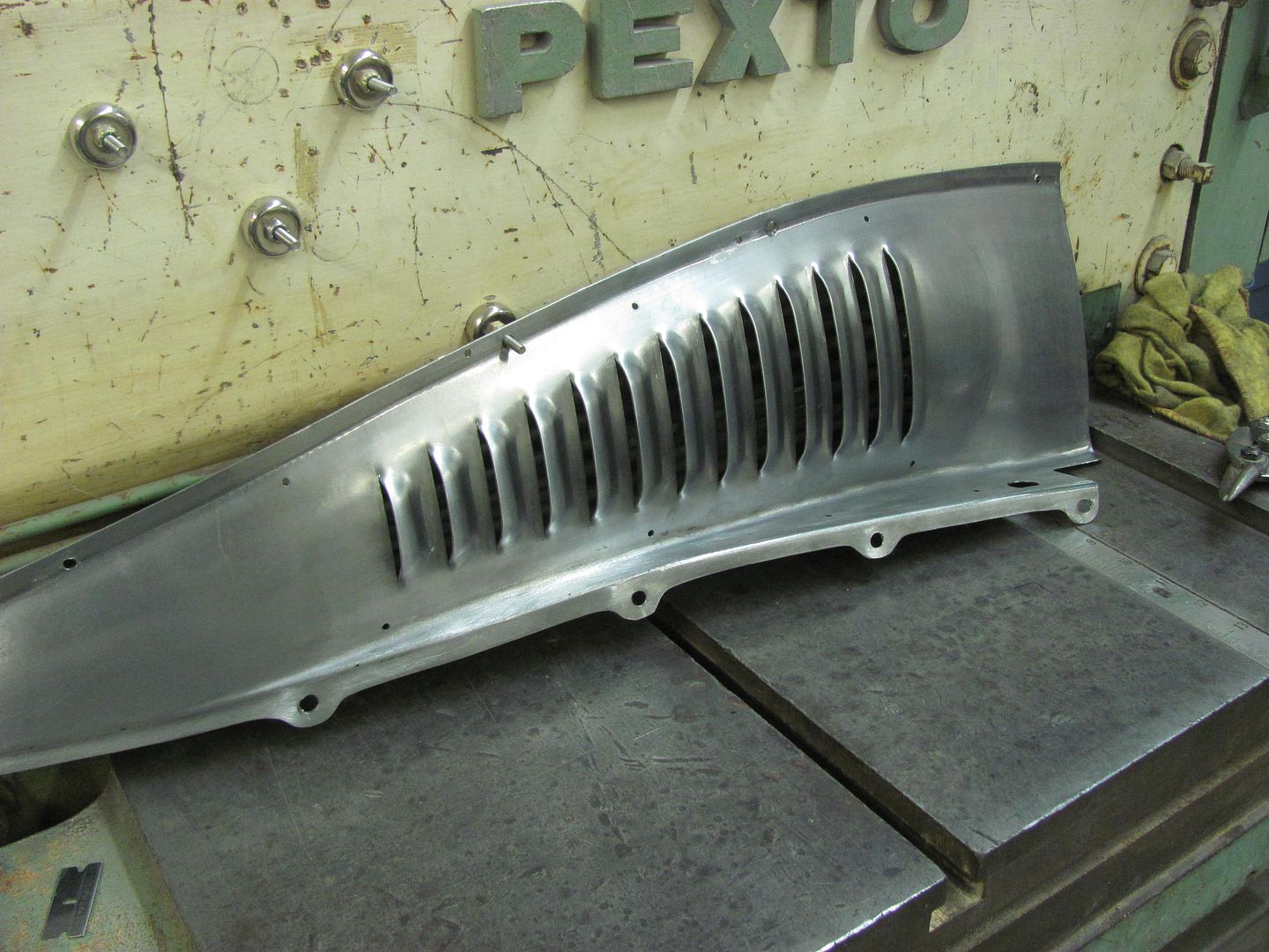
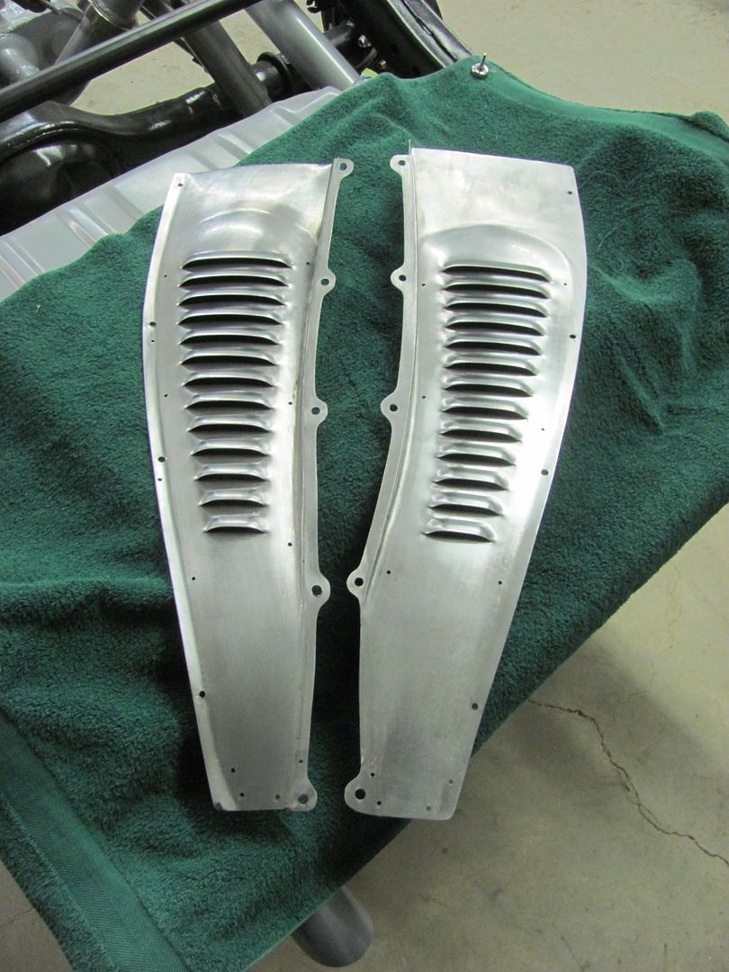
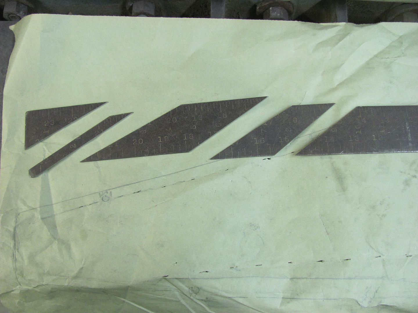
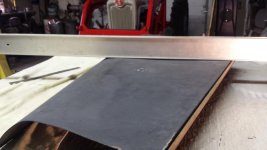
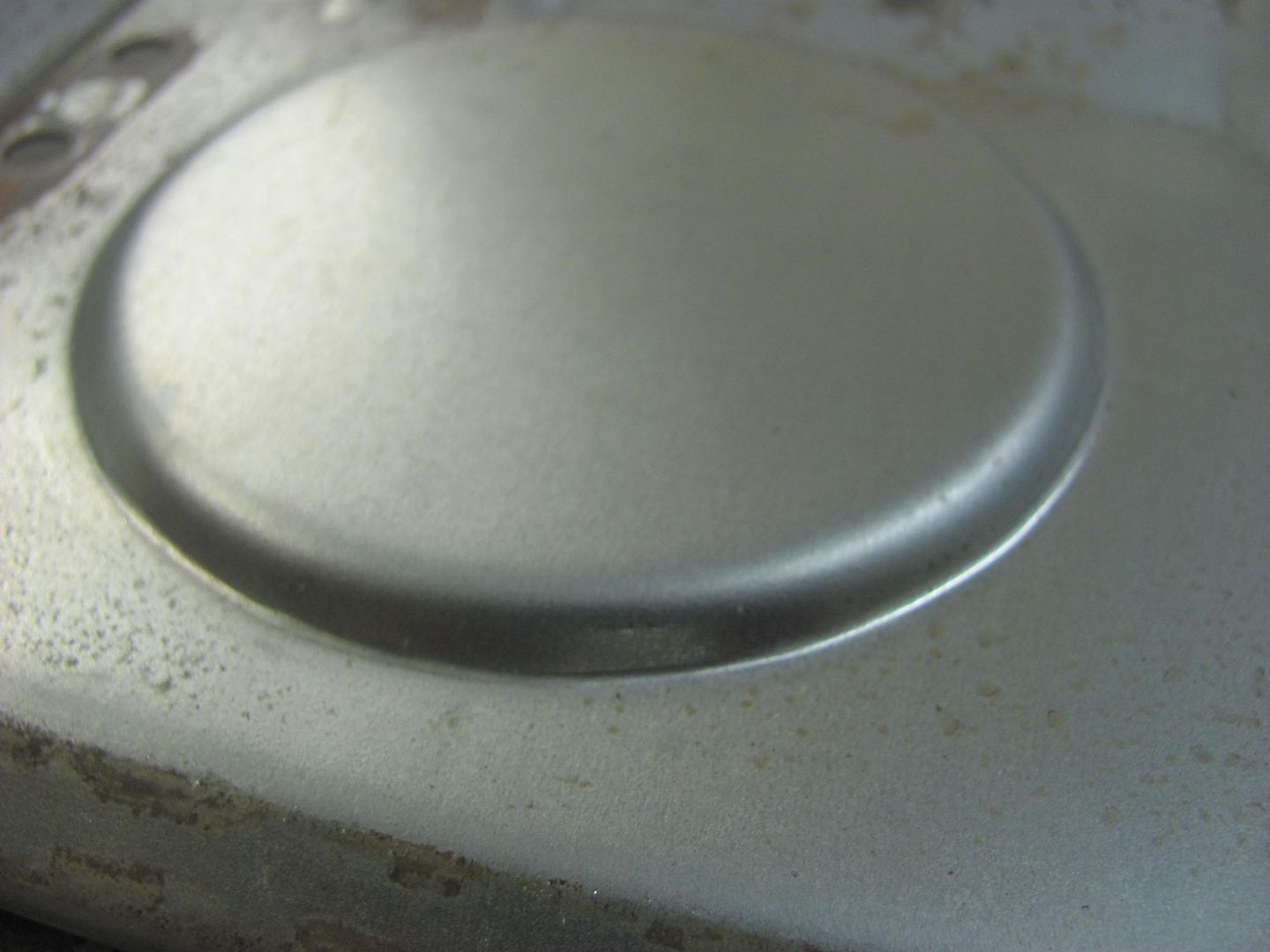
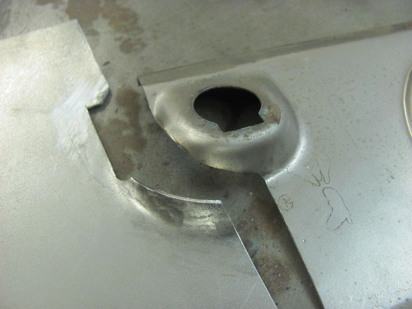
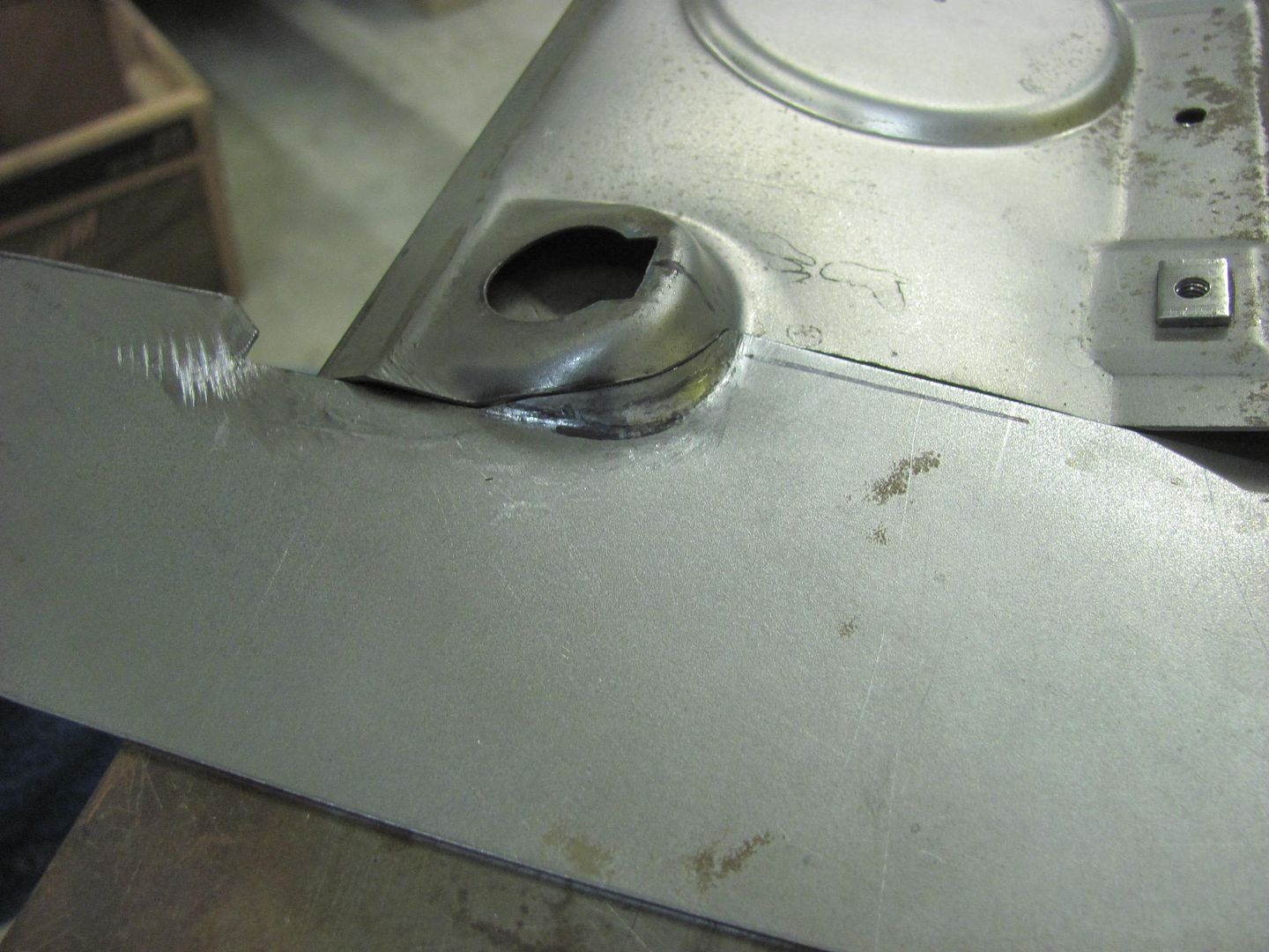
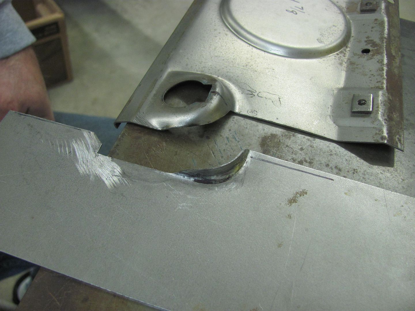
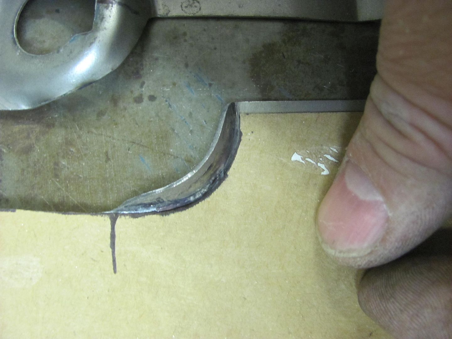
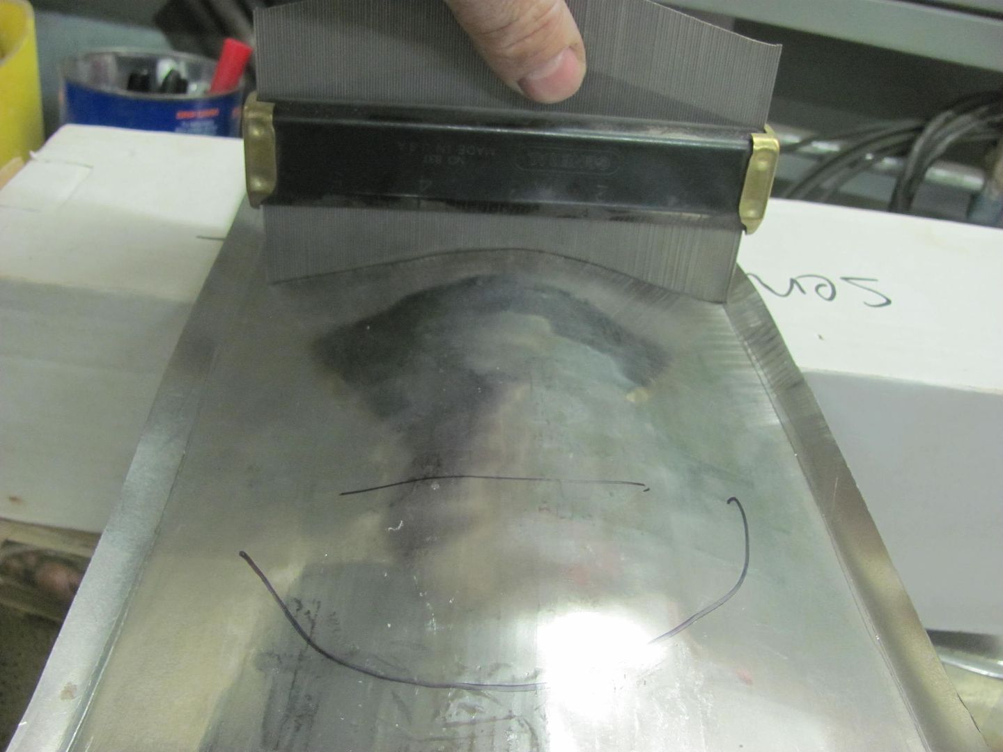
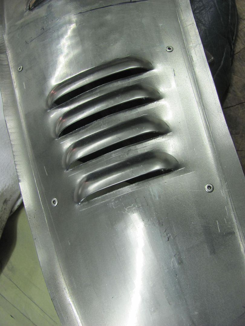
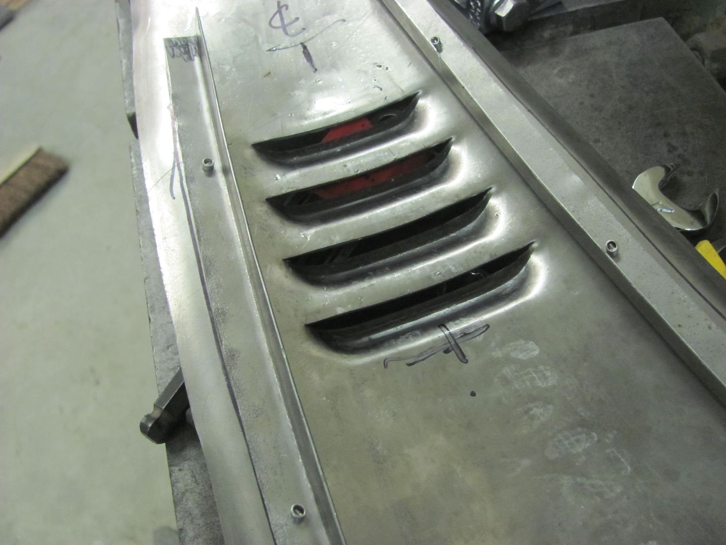
Looking at the louvers...
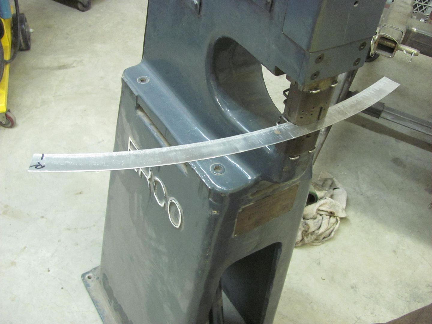
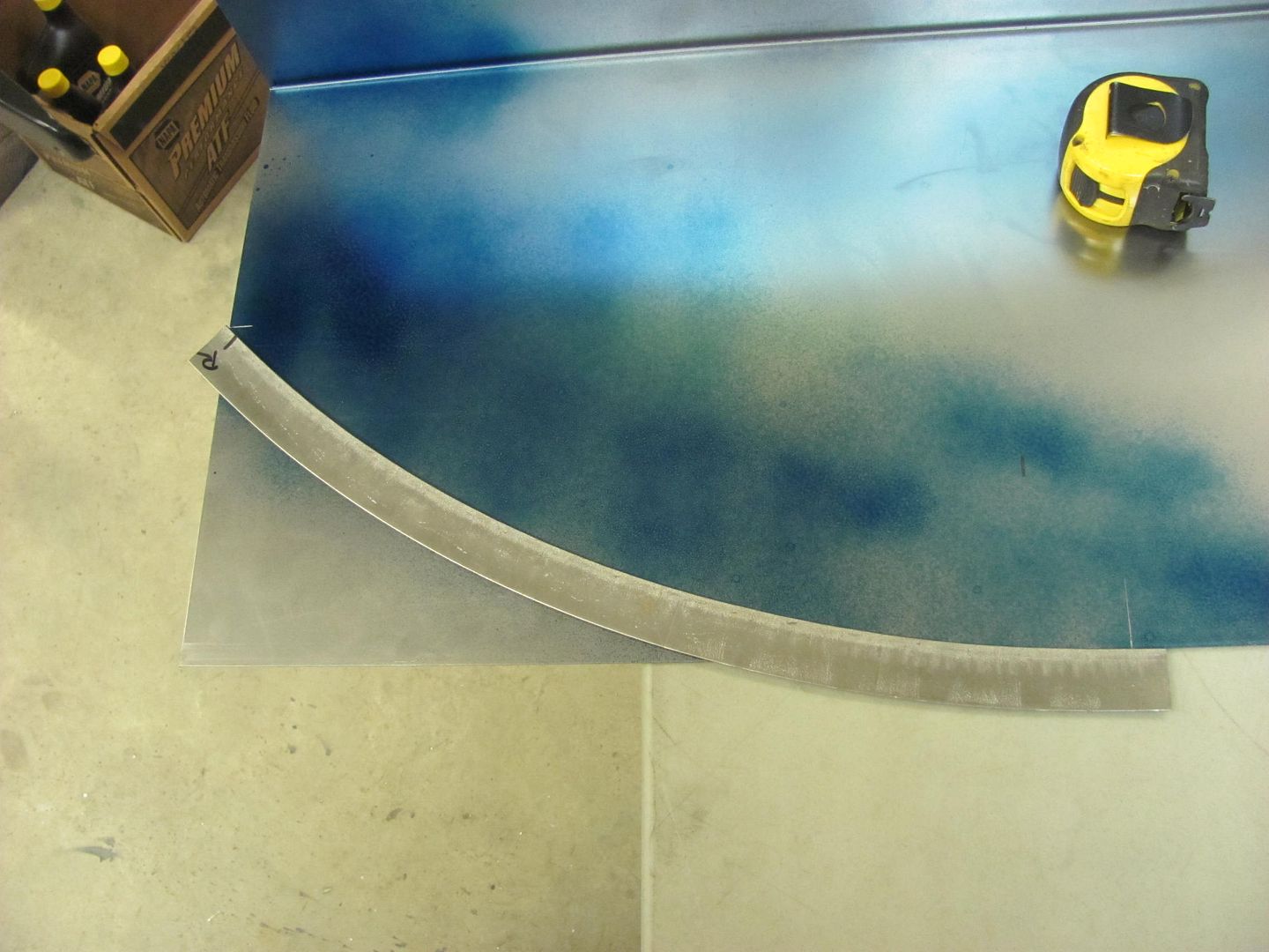
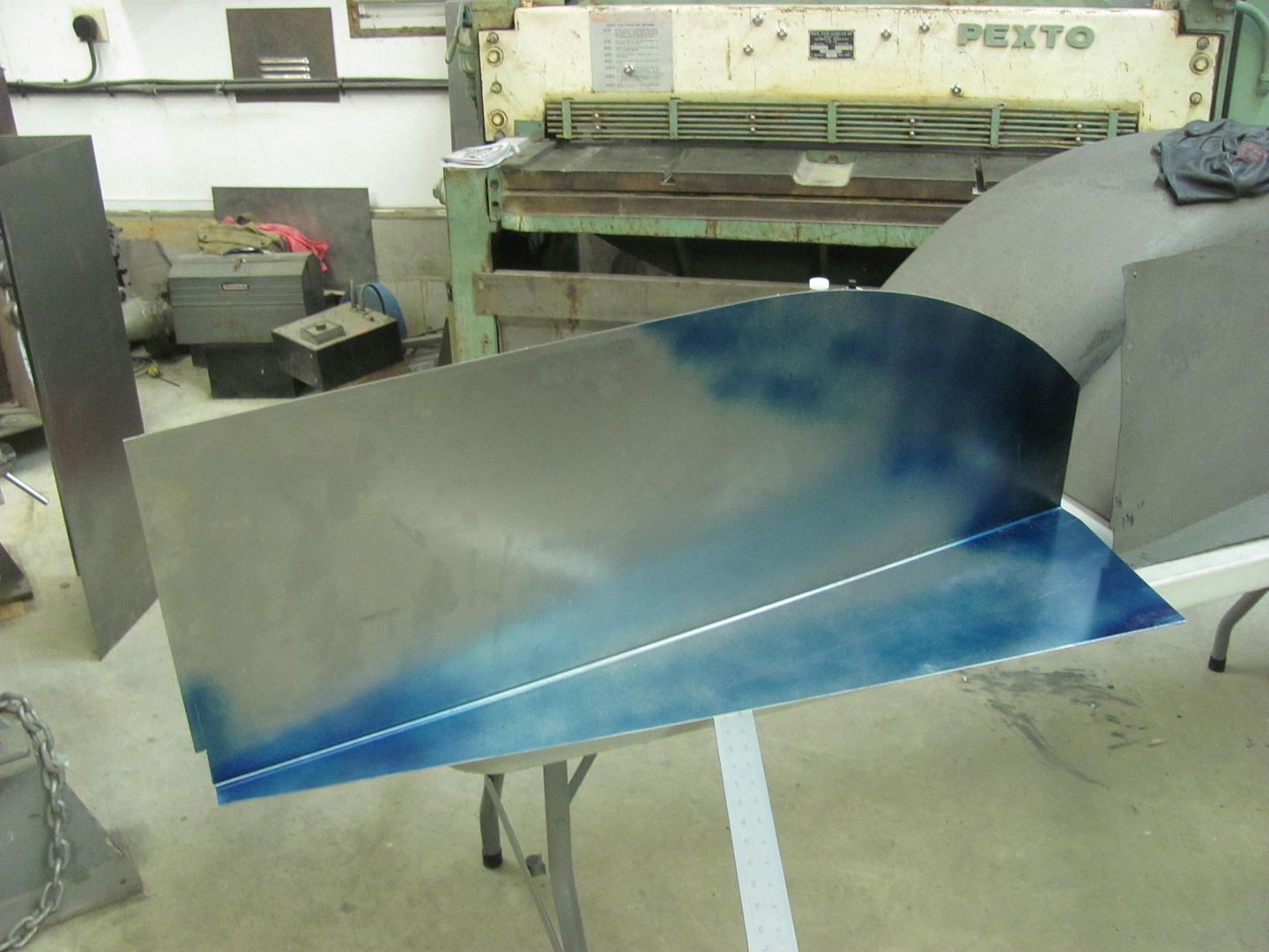
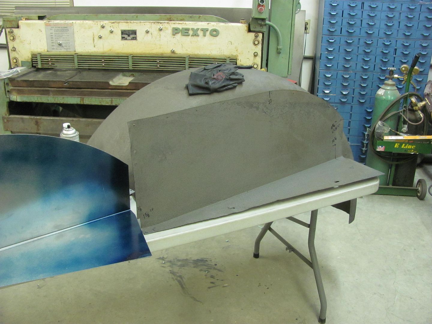
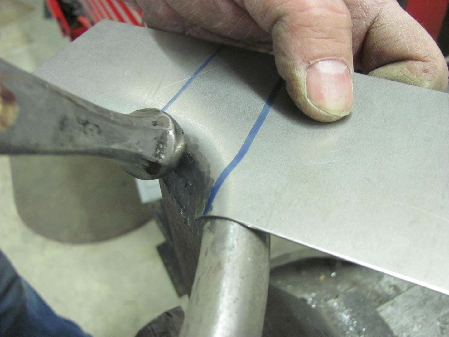
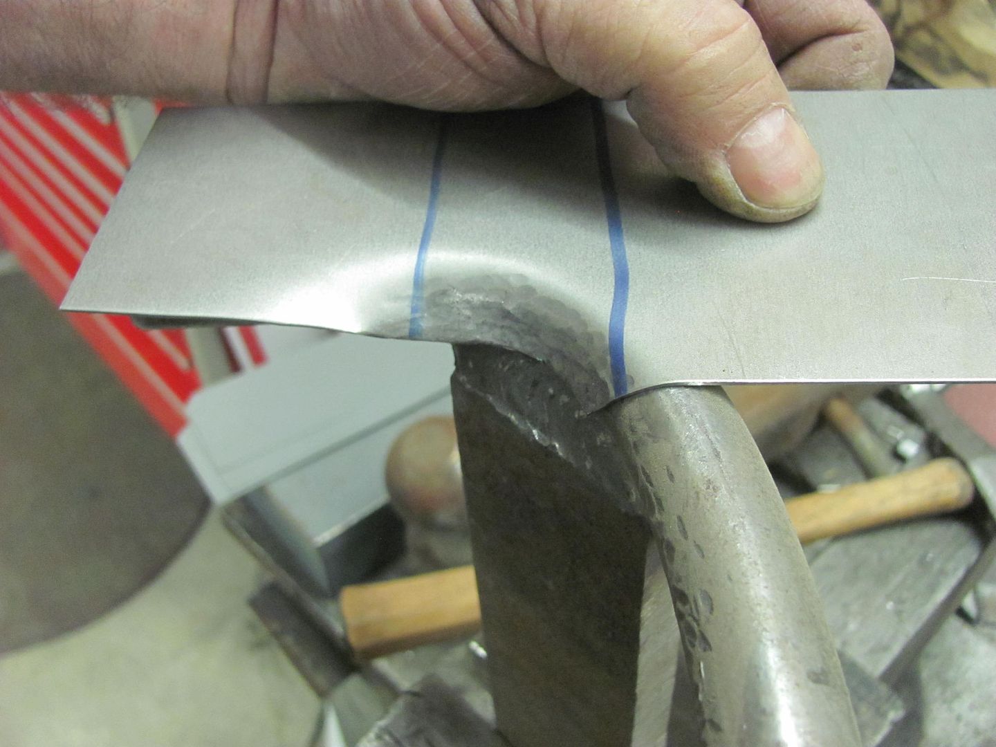

Action shots:


Picture%204208.jpg


Picture%204210.jpg


Picture%204215.jpg


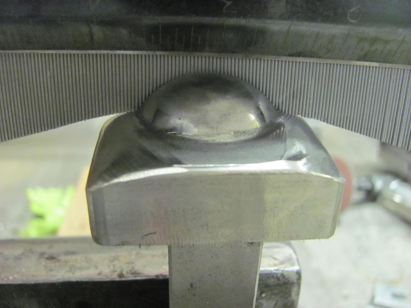
We have some more relieving to do on the tooling to eliminate some marking, then we'll do one more practice piece before breaking into the good stuff..
 
To avoid these ads, REGISTER NOW!
OP
M

MP&C

Well-known member
Joined
Oct 21, 2009
Messages
4,396
Location
Leonardtown, MD
Here's the next practice panel as compared to Cody's inner fender panel..


Picture%204217.jpg


Punching the louvers in the practice panel..


Here's the moment of truth, the inner fender ready for punching...


Picture%204220.jpg


Looks like our crown still exists!


Picture%204222.jpg


Picture%204223.jpg


Picture%204224.jpg


another view....


One down, one to go..
 

EdT

Well-known member
Joined
Sep 21, 2010
Messages
1,104
Location
North Georgia
Great demo on the radius louvers. I think it really gives folks an better idea of what's involved in some of the features that most people don't give a second thought to when they see them. The prep work, fixturing, tooling, and test pieces take way longer than the final event. So, at the end of the day, each of the final louvers is probably worth a couple of hours or more. But, all the prep work really shows in the final result. Great job and thanks for taking the time to share your efforts. Inspiring as usual.
 
OP
M

MP&C

Well-known member
Joined
Oct 21, 2009
Messages
4,396
Location
Leonardtown, MD
Thanks guys!


Finished the driver's side inner fender this morning..
Picture%204236.jpg


Picture%204235.jpg


Picture%204234.jpg


Picture%204225.jpg


Now to get them back to Cody so he can do some more re-assembly..
 
OP
M

MP&C

Well-known member
Joined
Oct 21, 2009
Messages
4,396
Location
Leonardtown, MD
After finishing the louvers this morning, we turned our attention back to the wagon. We started installing the brake lines and found the "kit" the owner had purchased was far from a direct fit. here's the booster and master cylinder we're using...


Picture%204228.jpg


Picture%204229.jpg


As the kit had no lines to fit a 9" rear, we used a stick of stainless tubing that was left over from the Fairlane job and bent our own.

Picture%204230.jpg


Picture%204231.jpg


Picture%204232.jpg
 
OP
M

MP&C

Well-known member
Joined
Oct 21, 2009
Messages
4,396
Location
Leonardtown, MD
Well most small jobs I do like this you never see the part installed (like the Studebaker dash parts) so I was happy to see Cody post up some pictures this morning. Here's a shot of the passenger side installed.. It was nice to take on a challenge like this and see it actually work.. :lol:


35ChevyInnerFender3.jpg


35ChevyInnerFender5.jpg


35ChevyInnerFender4.jpg


I think Kyle enjoyed the break from blocking epoxy primer.. Now back to the old grind..
 
OP
M

MP&C

Well-known member
Joined
Oct 21, 2009
Messages
4,396
Location
Leonardtown, MD
Was in the shop today and walked past a rolled sample piece of 18 ga that we had made using the go kart slick on the English wheel. Part of the test drive when it sold a week or so ago. Since louver tool was still in the machine, hey! Let's see how well it does with a tighter radius...


Radius%20Louver%201.jpg


Size compared to a 4-1/2" disc


Radius%20Louver%202.jpg


The coining was done manually with a corking tool. Some distortion, would fare better I believe in a machine with a taller throat. The Lennox is only about 6" high, where a bit more room would allow better clearance for setting up the rotational fixture.


Radius%20Louver%203.jpg


....and the motion picture..


So don't be intimidated by the next challenge, get out in the shop and make some scrap, learning in the process.
 
OP
M

MP&C

Well-known member
Joined
Oct 21, 2009
Messages
4,396
Location
Leonardtown, MD
Thanks!


Adding the rear axle vent hose, we needed a spot to anchor the second vent fitting to keep the hose from flopping around...


Picture%204237.jpg


Which is threaded with a 7/16-20 thread


Picture%204238.jpg


Picture%204239.jpg


With Loctite added to the threads...


Picture%204240.jpg


Picture%204241.jpg


More SS brake lines...


Picture%204243.jpg


Picture%204244.jpg


Picture%204245.jpg


Picture%204247.jpg


Picture%204248.jpg


With the rear brake lines complete, the rear wheels were bolted back up..


Picture%204250.jpg


And for our lessons learned, this is what happens when you cut 12 gauge steel with a square on the other end of the shear. Dan, the blades are still sharp!


Picture%204251.jpg


Picture%204252.jpg
 
Last edited:

gasgas17

Well-known member
Joined
Nov 7, 2009
Messages
443
Location
Nova Scotia, Canada
A former co-worker of mine was cutting some plywood while a steel framing square was laying on the saw horse underneath. It didn't cut near that pretty.
 

Fan Attic

Member
Joined
Dec 7, 2015
Messages
12
Location
SW Idaho
Hey Robert, another very nice touch on the wagon, thanks again for sharing. Neil got my shrinking dies and they should be on their way back better than new in the next day or two, Thank You for the lead.
Quite a ways back in one of your threads you covered removing an oil can. I have that write up printed and filed in my shop but have a little issue I can't quite equate to the two very well covered types of repair in your description. Could you possibly humor me with your suggestions for this situation?
I am restoring a 1936 Ford Pickup for a friend and am working now on the hood panels. Though they "looked" close the top panels both had slight creases along the outside radius from heavy stuff being stored on them. These have a very slight crown left to right and are flat front to back. I bumped the detectable damage back to nearly undetectable but both panels have a loose oil can in the center of the "flat" top which pressure around the perimeter does not prevent. Any hint on how to locate the sweet spot/spots? Thank you in advance for any thoughts you may have on this.
 
To avoid these ads, REGISTER NOW!

Fan Attic

Member
Joined
Dec 7, 2015
Messages
12
Location
SW Idaho
First try at pics on this site but let me try. If this works the first 3 are the right side hood top, the top of the outside radius with "straight edge" (sawyer's guide), and hinge edge with straight edge.
 

Attachments

  • 20160310_074655.jpg
    20160310_074655.jpg
    138.6 KB · Views: 130
  • 20160310_074724.jpg
    20160310_074724.jpg
    140.5 KB · Views: 122
  • 20160310_075026.jpg
    20160310_075026.jpg
    139.6 KB · Views: 124

Fan Attic

Member
Joined
Dec 7, 2015
Messages
12
Location
SW Idaho
The previous was supposed illustrate that the front to back is pretty flat on the edges. Next is front to back with edge supported and then center supported. Gravity and the support in the center is all that moves the low spot from the center to two low spots fore and aft of center. This seems to me to mean the edges are the right shape and I have too much metal in the middle, somewhere?
 

Attachments

  • 20160310_075156.jpg
    20160310_075156.jpg
    141.5 KB · Views: 84
  • 20160310_075009.jpg
    20160310_075009.jpg
    140.7 KB · Views: 78
  • 20160310_074905.jpg
    20160310_074905.jpg
    136.8 KB · Views: 77

Fan Attic

Member
Joined
Dec 7, 2015
Messages
12
Location
SW Idaho
These are same set of support conditions measured left to right.
 

Attachments

  • 20160310_075331.jpg
    20160310_075331.jpg
    133.6 KB · Views: 64
  • 20160310_075357.jpg
    20160310_075357.jpg
    132.7 KB · Views: 60
  • 20160310_075425.jpg
    20160310_075425.jpg
    128.7 KB · Views: 66

Fan Attic

Member
Joined
Dec 7, 2015
Messages
12
Location
SW Idaho
And finally a salute to you and others who have shared your knowledge with the rest of us. I've spent many, many hours studying your contributions. I would have never dreamed of attempting this just a few years ago. Maybe old dogs can learn a new trick or two if they want to!
 

Attachments

  • 20160310_075621.jpg
    20160310_075621.jpg
    138.7 KB · Views: 146
OP
M

MP&C

Well-known member
Joined
Oct 21, 2009
Messages
4,396
Location
Leonardtown, MD
Nice work!


I would think (subject to verification) that the hood should have a slight bit of crown front to back to give it a bit of support. If the opposite side is undamaged, or you know of another one local to you, I'd check the crown to see if there is any or if it's flat as you show. Next, it's possible that when you removed the crease around the "pucker", any on-dolly may have caused a slight amount of stretch, which in turn MAY have pulled at some of the metal in the center, causing the loose oil can. MAY have.. Does the outer perimeter of the (previous) dent seem to be real tight or can you cycle that in areas as well?
 

EdT

Well-known member
Joined
Sep 21, 2010
Messages
1,104
Location
North Georgia
I suppose this is relevant to the topic at hand. Some time ago I did a bit of arithmetic trying to figure out why the red hot dot method of shrinking actually works. Without all the boring math, the answer is that a tiny bit of extra metal between two fixed restraints creates a large hump. As an empirical test of the theoretical answer I did the following. I captured both ends of an 18" steel rule between two machinists clamps on the edge of a work surface. Each end of the ruler was touching the clamp on each end, but the ruler was not in compression nor was it loose. I then inserted a various feeler gauges between one of the clamps and the end of the ruler to see how much the center of the ruler rose off the bench surface. A .005" feeler made a .090" hump in the middle of the ruler. So, it doesn't take much extra metal to make a big bulge or, in this case, a loose oil can.
 
OP
M

MP&C

Well-known member
Joined
Oct 21, 2009
Messages
4,396
Location
Leonardtown, MD
Thanks for adding that info Ed, good to see some "investigation" going on!

While we are waiting on some brake and front end parts to show up so we can finish the frame, Tonight in the shop we decided to work on John's front fenders for the 1947 Biederman Truck, seen here for reference:

Picture%203604.jpg


The fenders are made using 16 gauge steel, so this may be a bit challenging when we get to blocking and wheeling patches for the fenders themselves. In the meantime (while still waiting for the new English wheel) let's get started on the inner fenders. The driver's side is the worst, with so much rotted away that we couldn't get accurate dimensions. The passenger side was in much better condition, but just shy of 70 years has taken its toll in adding some wavy distortion. So we'll remake both sides for a better match.

Picture%203644.jpg


In order to get a more crisp bend on the 16 gauge steel, we used a tipping die in the Lennox to thin the metal at the line of the bend.

Picture%204254.jpg


Picture%204261.jpg


Picture%204265.jpg


Bending in the Baileigh Magnetic Brake..

Picture%204258.jpg


Picture%204267.jpg


Picture%204268.jpg


Picture%204270.jpg


This detail shot shows how the thinning helps get a tighter bend..

Picture%204260.jpg


Next, we needed a profile template for the rear radius, so the kick shrinker is used on a folded 19 gauge strip to add the radius..

Picture%204279.jpg


Picture%204278.jpg


A flat folded strip works better than an angle as if you shrink too far in this direction.....

Picture%204280.jpg


......you can simply shrink the back half to reverse the effect without the need for changing to the stretching die..

Picture%204281.jpg


Now with an accurate pattern, we can use the template on the new inner fender..

Picture%204282.jpg


Picture%204286.jpg


All trimmed...

Picture%204290.jpg


Picture%204291.jpg


With the new clamped to the old, we can see what the years of abuse has done..

Picture%204292.jpg


One down, one to go..
 

Fan Attic

Member
Joined
Dec 7, 2015
Messages
12
Location
SW Idaho
"I would think (subject to verification) that the hood should have a slight bit of crown front to back to give it a bit of support. If the opposite side is undamaged, or you know of another one local to you, I'd check the crown to see if there is any or if it's flat as you show. Next, it's possible that when you removed the crease around the "pucker", any on-dolly may have caused a slight amount of stretch, which in turn MAY have pulled at some of the metal in the center, causing the loose oil can. MAY have.. Does the outer perimeter of the (previous) dent seem to be real tight or can you cycle that in areas as well?

__________________
Robert"

Thank you again for the quick reply Robert, I only get a little play time in the morning over coffee so I usually don't get to see the computer the rest of the day. I may have to make an exception. I didn't measure the left hood top but it had similar damage and has a similar loose oil can in the center, and both halves had this oil can problem even before bumping the creases out of the top of the outside radius. Like a lot of "projects" this one was used to stack junk on for the past 30 years.
To answer your questions, all I have is the interweb for reference right now but the attached are what I started with and what the owner wants. I won't be the painter! As far as I can tell the top panels are flat front to back from the center hinge to the outside radius. The hinge has to be straight to work. The previous "dent" was really just a series of small ridges at the top edge of the radius where heavy stuff had pushed the middle of the hood top down over the years. Once I bumped the ridges back down and the "flat part" back up, off dolly, the radius does not cycle anywhere along its length on either panel. The hood gets structure from the center hinge, the outside radius and support front and back from the cowl and grill shell. I need to measure those today to see how much crown they have. I may also mock up the end supports to see what the crown does to the oil can as the truck is in a million pieces right now.
Thank you again for your guidance.
 

Attachments

  • 20151209_115636.jpg
    20151209_115636.jpg
    152.3 KB · Views: 91
  • Finished.JPG
    Finished.JPG
    56.4 KB · Views: 87
OP
M

MP&C

Well-known member
Joined
Oct 21, 2009
Messages
4,396
Location
Leonardtown, MD
Today we got the second inner fender cut out, and took them both over for a test fit on the truck

Picture%204303.jpg


Picture%204304.jpg


The driver's side has a bolting plate in the middle of the frame for the steering box, so a relief notch was in order...

Picture%204306.jpg


....as well as a bit of trimming for some clearance so that the paint won't be chipped off on the first test drive. The fabrication of these parts are done, and we should pick up the new Tommasini Wheeling Machine this coming weekend so we can get started on the fender patches..

Picture%204307.jpg


Picture%204308.jpg


Picture%204309.jpg


We started on an ashtray delete mod for the wagon, starting with this...


Picture%204310.jpg


Picture%204314.jpg


a bit wider opening...


Picture%204334.jpg


Now to remove the glove compartment door "skin"......


Picture%204315.jpg


Picture%204317.jpg


Picture%204318.jpg


Then used these to flatten out the flanges...


Picture%204319.jpg


Picture%204320.jpg


Picture%204321.jpg


Looks like someone may have kneed the glove box at some point...


Picture%204322.jpg


Picture%204323.jpg


The inside looks real nice for 61 year old metal, still shining!


Picture%204325.jpg


Now time for the post anvil...


Picture%204327.jpg


Picture%204328.jpg


Picture%204330.jpg


Here's our widening method for the inner door and the outside will get a new skin made up..


Picture%204326.jpg


Picture%204331.jpg
 

WoodsTruck

Well-known member
Joined
Jan 12, 2013
Messages
1,019
Question about the use of your tipping die for bending a straight line.

What would happen if you made the divot on the back side of the bend instead of the front? I realize you are referring to this as "thinning" the metal, but aren't you actually forging it in a sense since you aren't actually removing metal but compacting it primarily? To my inexperience it would seem that a tight bend could be made without the resulting trough if the tipping die was used on the backside of the bend.

Fantastic work though, wish I had half the knowledge and tools to do that stuff. I'm a graduate of the BFH school.
 
OP
M

MP&C

Well-known member
Joined
Oct 21, 2009
Messages
4,396
Location
Leonardtown, MD
WoodsTruck said:
Question about the use of your tipping die for bending a straight line.

What would happen if you made the divot on the back side of the bend instead of the front? I realize you are referring to this as "thinning" the metal, but aren't you actually forging it in a sense since you aren't actually removing metal but compacting it primarily? To my inexperience it would seem that a tight bend could be made without the resulting trough if the tipping die was used on the backside of the bend.

Fantastic work though, wish I had half the knowledge and tools to do that stuff. I'm a graduate of the BFH school.


Here's the test from tonight. The 16 ga thickness measured out to about .057, at the "thinning" groove it was .053, so we lost about .004 in thickness, or less than 10%. Put the thinning groove on the outside for this bend, it tended to stretch the deformity back out again where it looks like it could be more readily cleaned up with a file..


Picture%204337.jpg


Picture%204338.jpg


So where the bending process allowed the groove to stretch back out....


Picture%204341.jpg


...it also gave us a wider radius than when the thinning was placed on the inside of the bend...


Picture%204342.jpg


So I'd say to use placement based on the radius needed or whether you need it dressed out. Given our original intent was a tighter/sharper radius, I'd place the thinning inside the bend to support that..
 
Last edited:

EdT

Well-known member
Joined
Sep 21, 2010
Messages
1,104
Location
North Georgia
Thanks for taking the time to run the bending experiment. The results are pretty much what I'd expect. When the score line is on the inside of the bend the material that would normally have to be compressed to accomplish the bend it not there so the bend can be tighter. With the score on the outside, the nominal thickness is reduced a bit leading to a tighter bend than the original material, but there is still material to compress on the inside of the bend. The opening up of the score line on the outside of the bend gives some idea of how much the outside has to stretch to make the bend. As a crossover between disciplines, in jewelry making, the jeweler making a box like piece out of flat stock files the insides of the bend lines to reduce the material thickness locally so that the bends come out nice and sharp. In that case material is actually removed rather than simply displaced, but the result is similar. I was half expecting the outside score sample to tear along the line. Looks like it might have been close. Glad to see the magnetic break in use. I got one last year and I am still exploring it's uses. Cool piece of kit in any case.
 

shortykorte

Well-known member
Joined
Sep 1, 2014
Messages
8,034
Location
Tallahassee, Fl
Wondering why the metal template for the curve versus cardboard. Here is my ideas:
Keeps curved edge crisp
Kyle practice shrink/stretch
Can be saved for future projects and you end up with a nice set of French curves or radius.
Show us newbies new tips/tricks.
 
OP
M

MP&C

Well-known member
Joined
Oct 21, 2009
Messages
4,396
Location
Leonardtown, MD
Thanks guys!


Kyle continued on reshaping the opening for the glove box, and I got started in trimming the filler panel for the inner glove box door....


Picture%204343.jpg


Picture%204344.jpg


Picture%204345.jpg


To try and keep our shape around the lock cylinder symmetrical, we cut out a profile template...


Picture%204346.jpg


Picture%204347.jpg


Adding the bends....


Picture%204348.jpg


Picture%204349.jpg


Looking for a proper sized circle pattern, Mickey Thompson comes through...


Picture%204350.jpg


Picture%204351.jpg


Picture%204352.jpg


Some bead roller action...


Picture%204353.jpg


Picture%204355.jpg


Picture%204356.jpg


Some TIG welding, we'll finish this up next time..


Picture%204357.jpg
 
To avoid these ads, REGISTER NOW!
Top Bottom