
You are using an out of date browser. It may not display this or other websites correctly.
You should upgrade or use an alternative browser.
You should upgrade or use an alternative browser.
MP&C Shop Projects
- Thread starter MP&C
- Start date
JonBoehman
Well-known member
Once again man, You are and inspiration.
Thanks Jon!
Spent some time in the shop tonight finishing the other weld but I was on a roll and forgot the in process pics.. Have to get a new photographer, this one just isn't working out..
Or the motion picture...
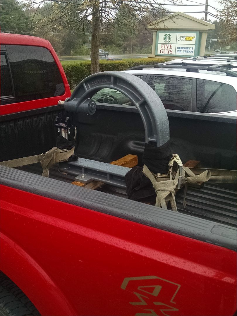
The new Tommasini Wheeling machine is on it's way north from Rock Hill SC, we'll be picking it up this weekend. Once it's set up we can whip out the new glove box door skin..
Spent some time in the shop tonight finishing the other weld but I was on a roll and forgot the in process pics.. Have to get a new photographer, this one just isn't working out..
Or the motion picture...
The new Tommasini Wheeling machine is on it's way north from Rock Hill SC, we'll be picking it up this weekend. Once it's set up we can whip out the new glove box door skin..
jimkinney
Well-known member
Nice work on the cup holder mod.
Are you going to replace the vinyl cork when you're done?
Jim
Are you going to replace the vinyl cork when you're done?
Jim
I think we'll stop at the painting, no contact paper this time. 
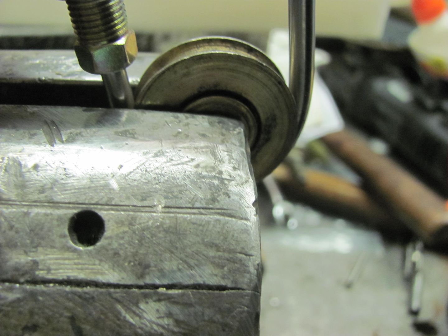
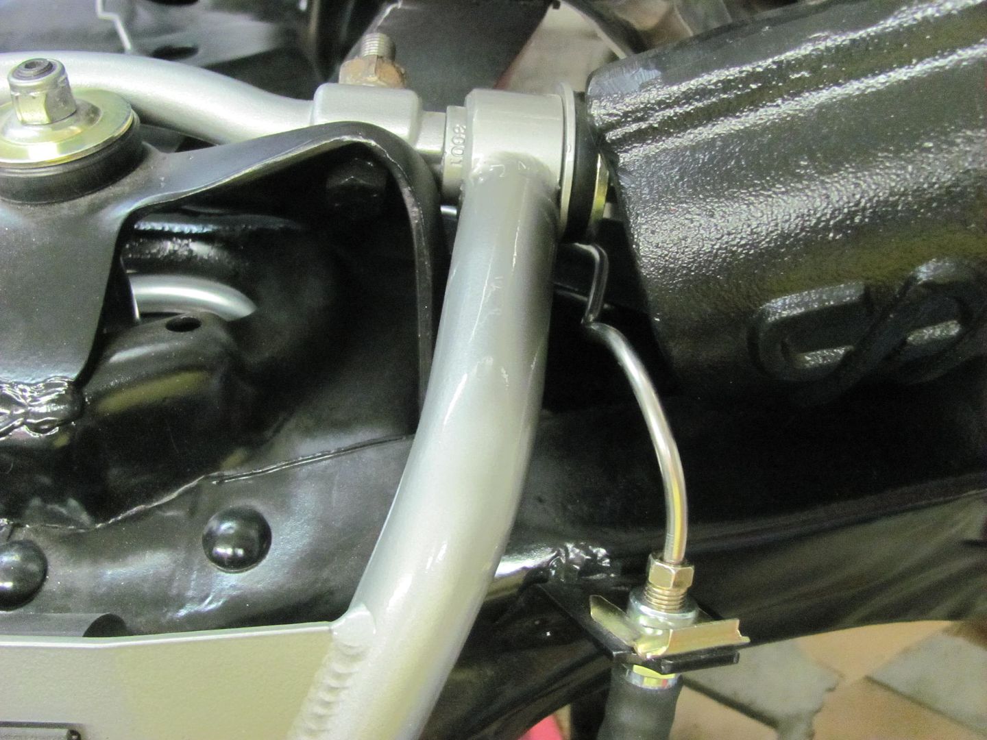
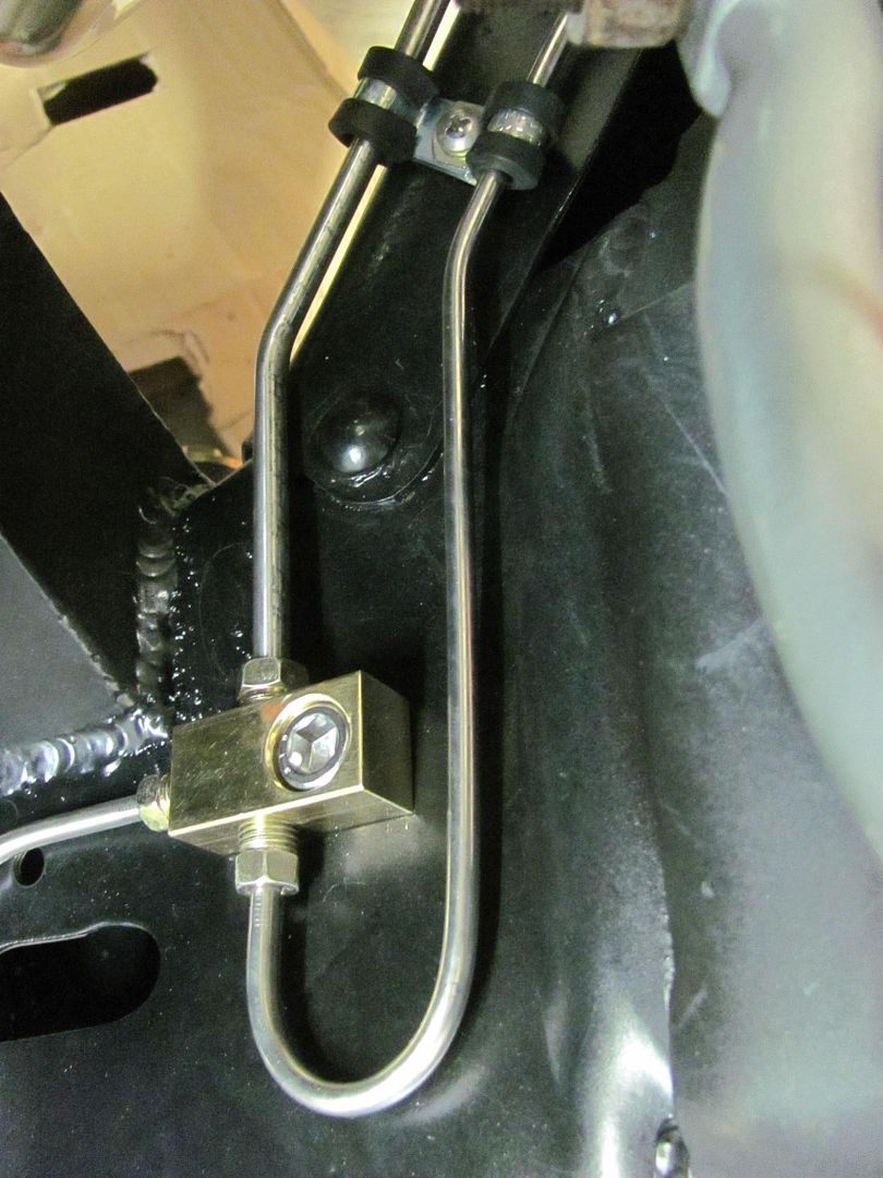
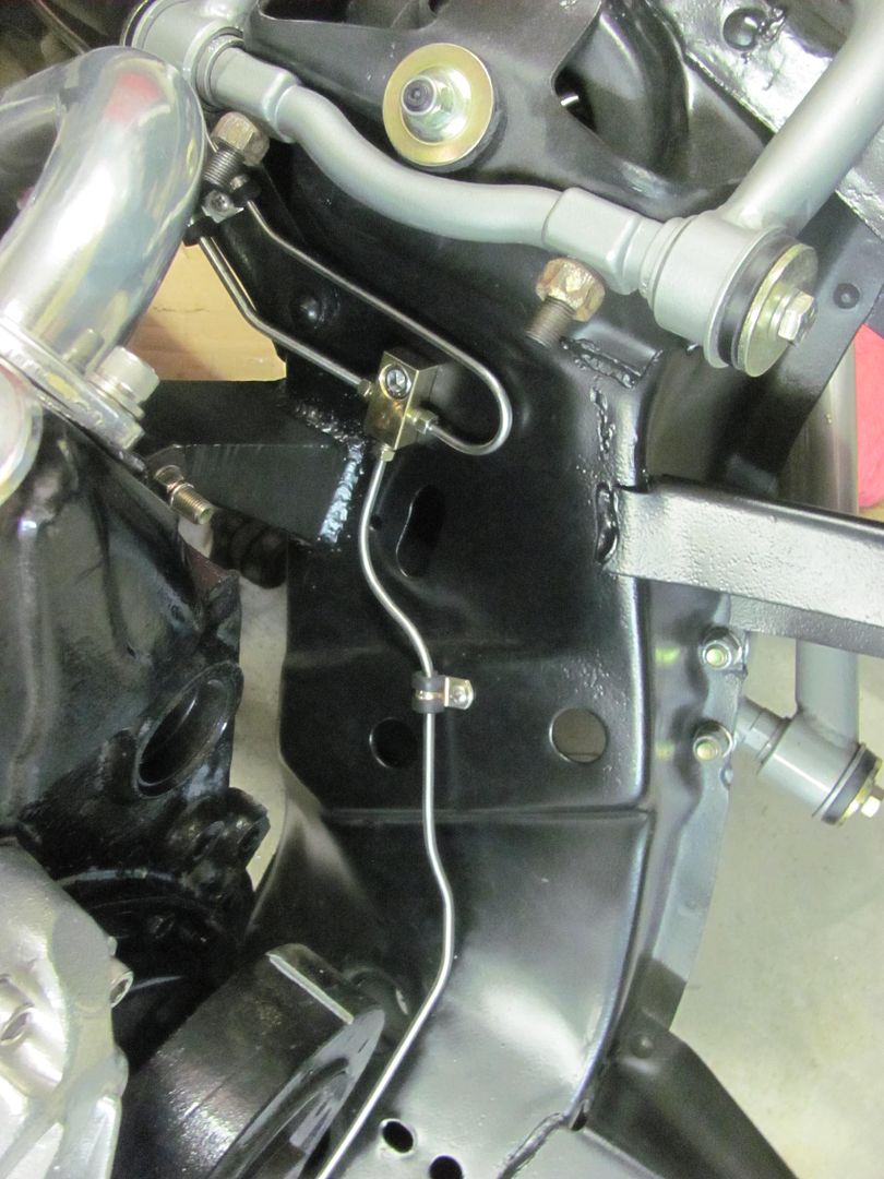
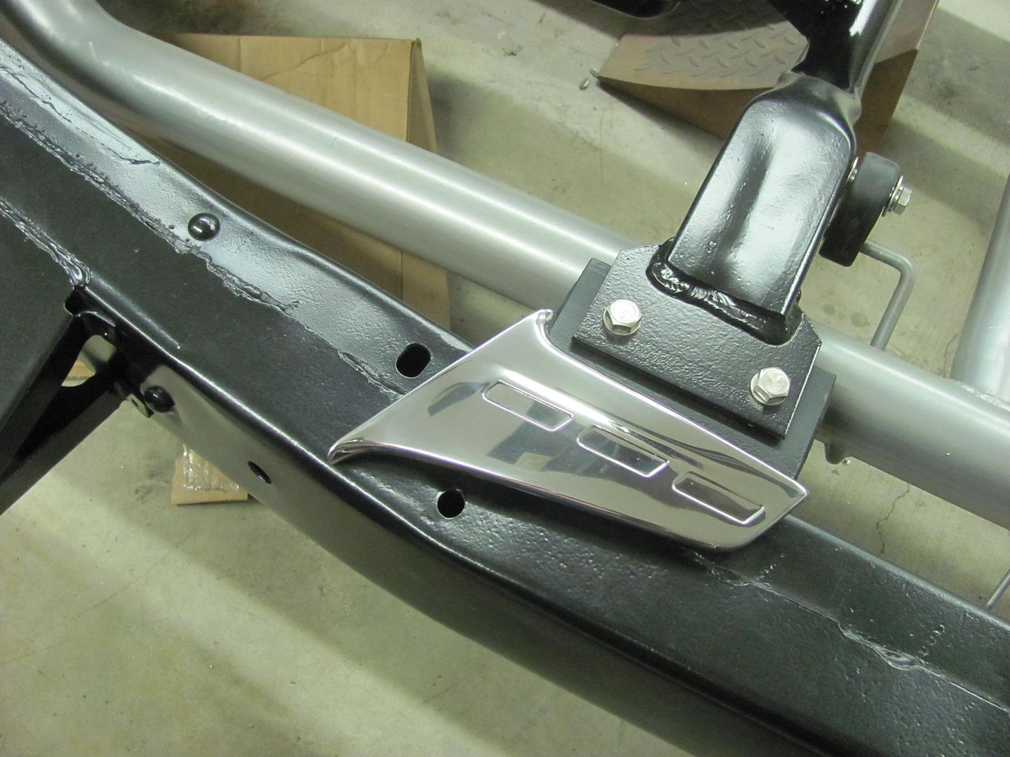
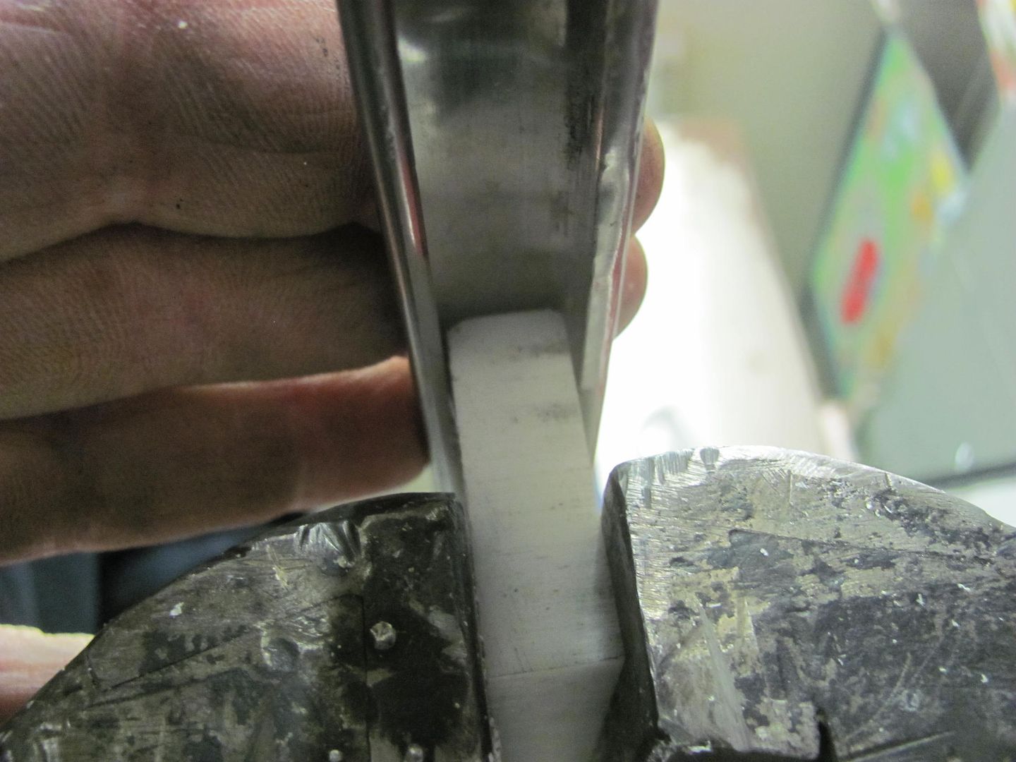
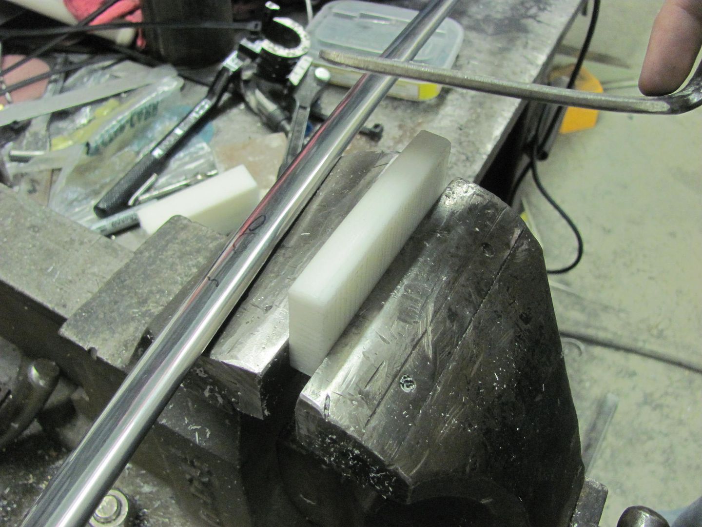
The front brake line distribution block showed up, so let's get the front lines finished up.. My tubing bender was not getting the nice small radius I was looking for, so time for a new tool. Here's a pulley out of the furniture and hardware parts bins at the local Ace store..
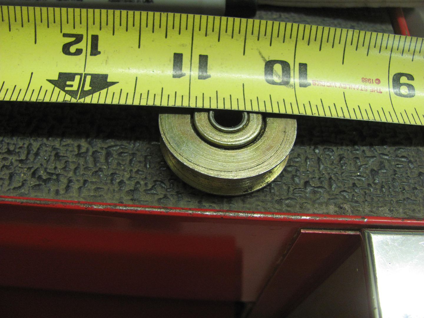
Here's the comparison to the tubing bender..
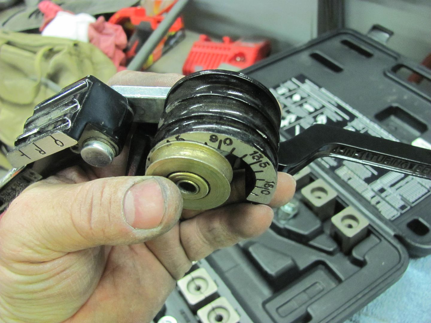
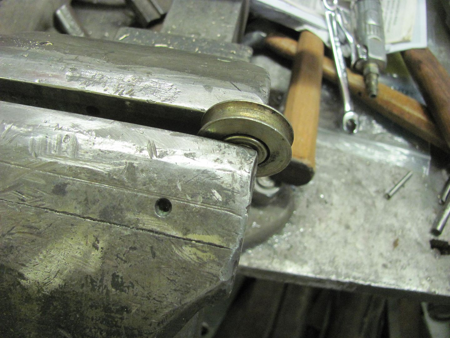
Bending the tubing...
The front brake line distribution block showed up, so let's get the front lines finished up.. My tubing bender was not getting the nice small radius I was looking for, so time for a new tool. Here's a pulley out of the furniture and hardware parts bins at the local Ace store..
Here's the comparison to the tubing bender..
Bending the tubing...
stinkity stoink
Well-known member
Awesome idea !!!!! Great work as always !!!
TimeWarpF100
Well-known member
Your photographer and my painter must be related . .
Your photographer and my painter must be related . .
Good help is hard to find...
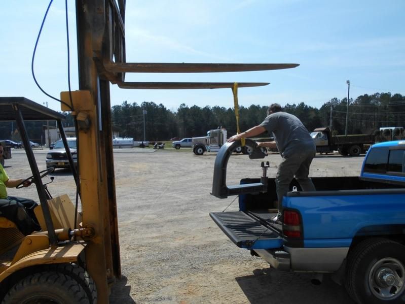
Well it wasn't supposed to rain in the mid-Atlantic states today until later tonight, but wouldn't you know, loading something in the back of the truck at Kirk's just seemed to coax the precipitation from the sky.
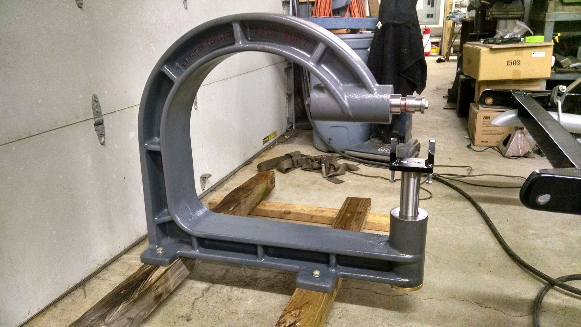
And here we are, unloaded back in the shop, still needing to make the stand. I'll pick up some materials likely on Monday..
Capt Chrysler
Well-known member
Hello Robert,
Check out these tubing benders. They are priced a little high, but they work!
Normal disclaimer: Don't own the company, don't sell them. Do have them in the tool box and use them. They work well!
Capt. Chrysler
http://www.fragolaperformancesystems.com/specialtoolsandaccess/toolsandaccess.html
Check out these tubing benders. They are priced a little high, but they work!
Normal disclaimer: Don't own the company, don't sell them. Do have them in the tool box and use them. They work well!
Capt. Chrysler
http://www.fragolaperformancesystems.com/specialtoolsandaccess/toolsandaccess.html
Those look to have a much nicer bend radius, may have to add to the collection! Thanks, like I need help spending money on tools
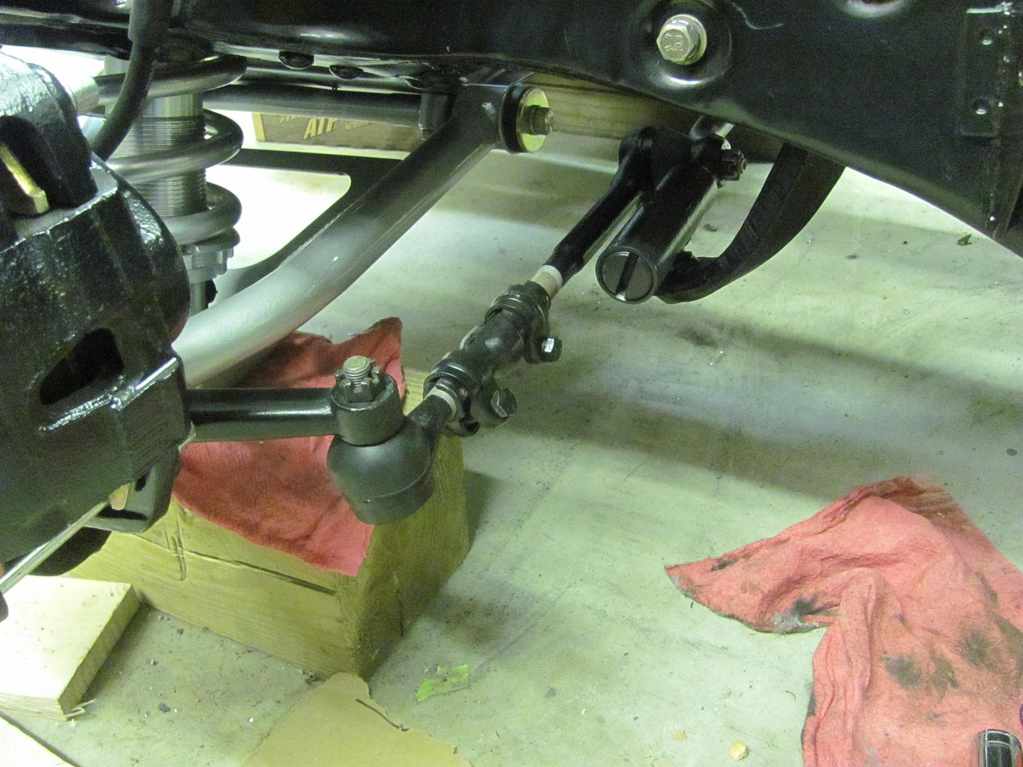
Tonight Kyle did some more media blasting as I was installing the idler arm bushings. Finally the drag link is off the floor, Thurs night we should get the front tires back on so we again have a roller..
Then we worked on some stainless just to show Kyle another aspect of restoration. There were some minor scratches that the buffing wheels wouldn't begin to take out, so we opted for some 600 then 1200 w/d cross hatching, then moved to the 1500 then 3000 Trizact on the DA using the foam interface pad. With scratches gone, back to the buffing wheels...
Videos:
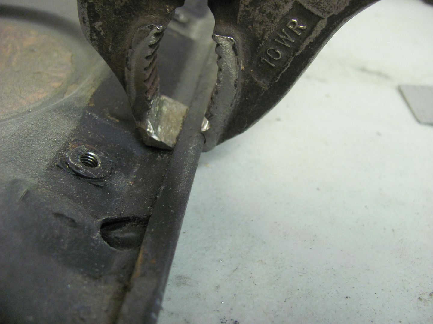
Love that modded Vise-Grip. Don't think you can walk into a store and pick that off the shelf.
")
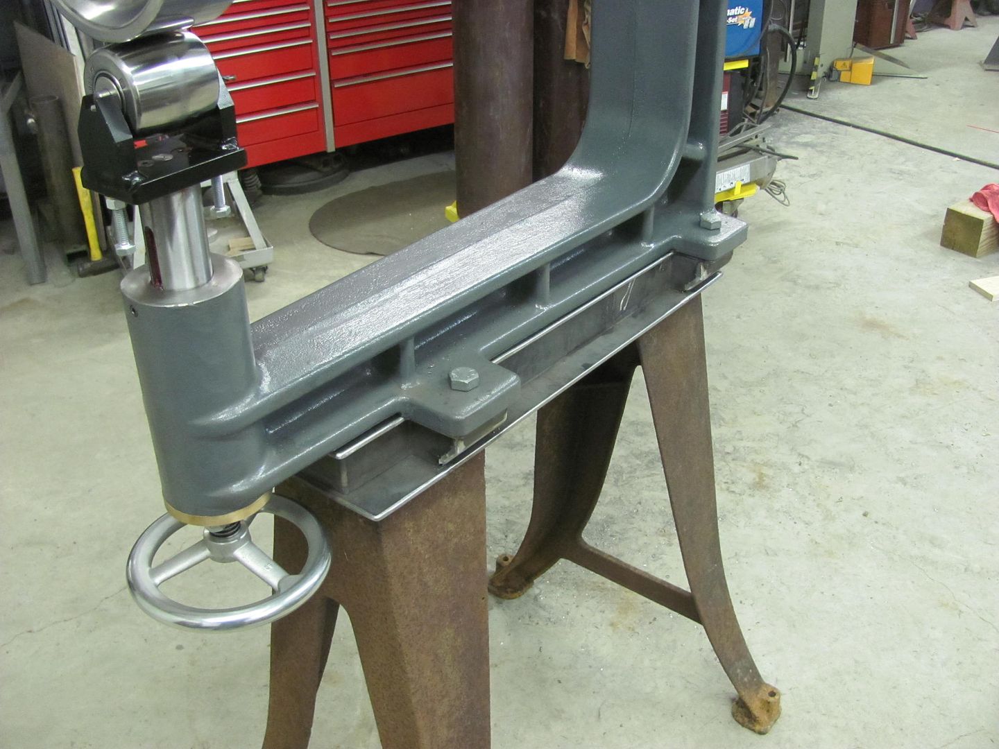
First off, yes, it's still bolted to the pallet.
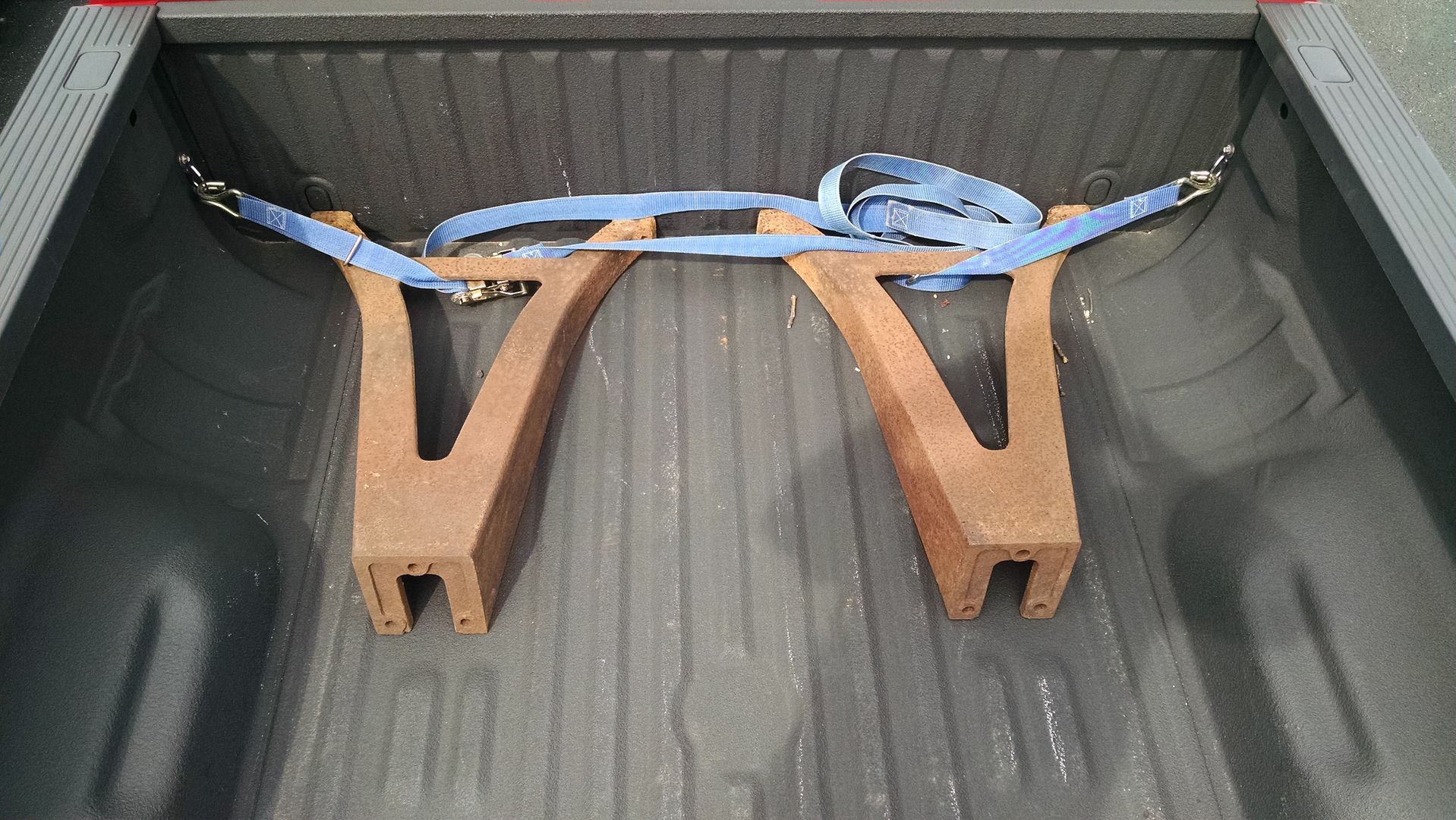
After seeing Kirk's cast legs he had squirreled away, I just couldn't bring myself to use fabricated legs for mine. So today was spent driving a 5 hour round trip to pick up some suitable legs..
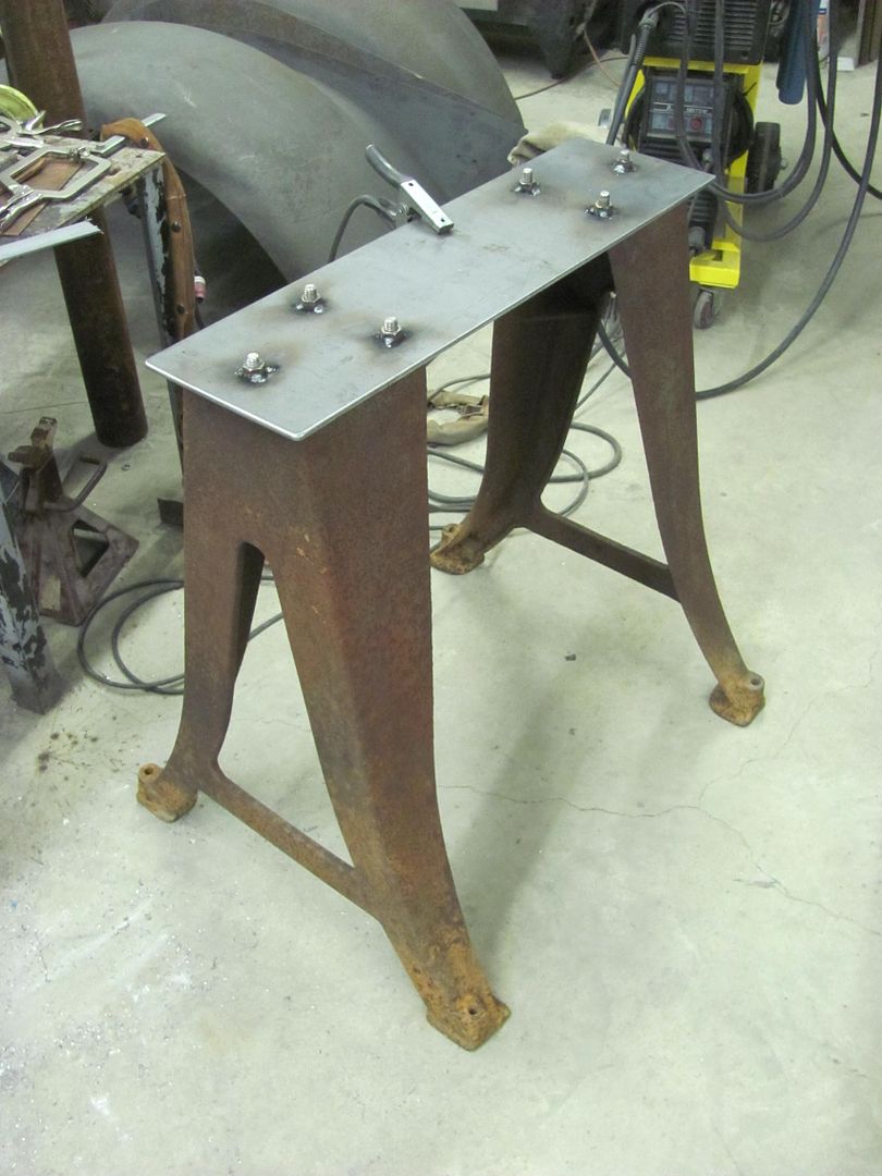
Here's the lower plate, and by my estimation I need about 4 inches of rise, so it will get some riser plates between the bottom plate and top plate..
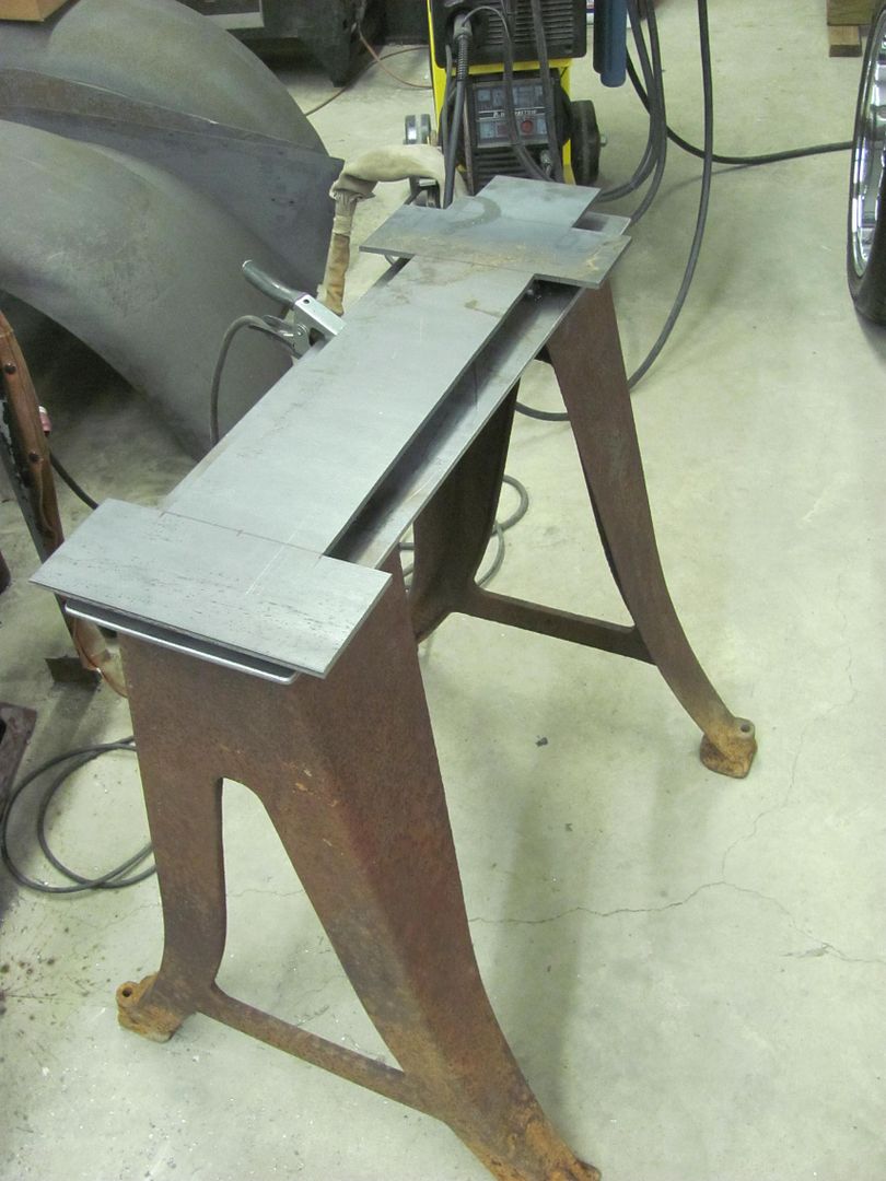
More to come..... need to find a nice bright color that will have Peter in sunglasses for his next visit..
After seeing Kirk's cast legs he had squirreled away, I just couldn't bring myself to use fabricated legs for mine. So today was spent driving a 5 hour round trip to pick up some suitable legs..
Here's the lower plate, and by my estimation I need about 4 inches of rise, so it will get some riser plates between the bottom plate and top plate..
More to come..... need to find a nice bright color that will have Peter in sunglasses for his next visit..
xtremek
Well-known member
Cool legs, CL?
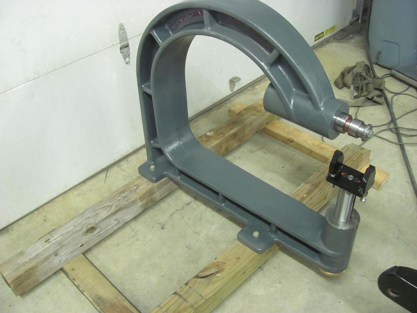
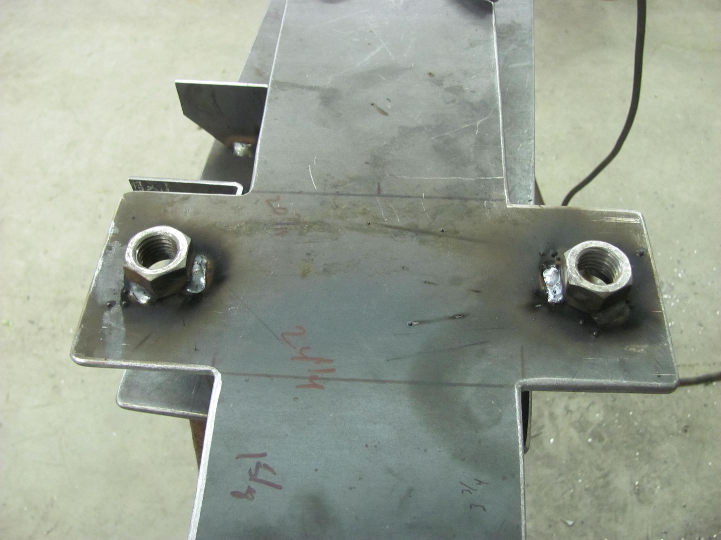
Finishing up on the English wheel, the legs are bolted on with 1/2" bolts with nuts welded inside the riser.
The wheel is held on with 3/4 bolts, with nuts welded inside the top plate of the riser.
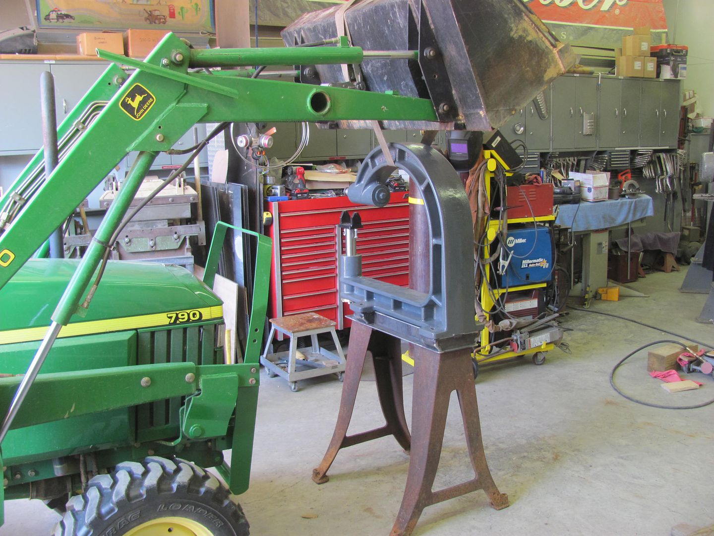
The John Deere lift device....
The wheel is set up at 48-1/2"
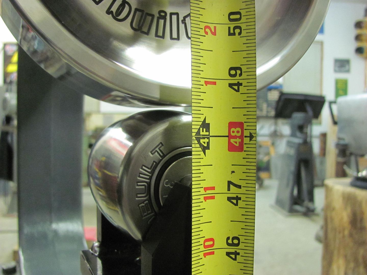
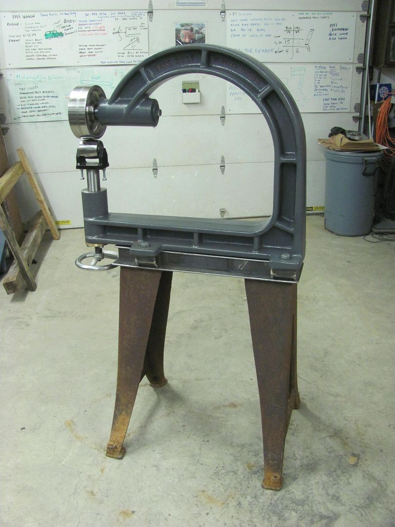
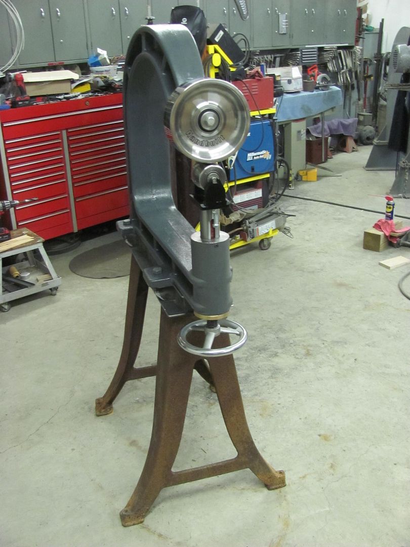
We wheeled a couple scrap panels, crushed some tucks, tipped a panel. Very pleased with the new wheeling machine.
The wheel is held on with 3/4 bolts, with nuts welded inside the top plate of the riser.
The John Deere lift device....
The wheel is set up at 48-1/2"
We wheeled a couple scrap panels, crushed some tucks, tipped a panel. Very pleased with the new wheeling machine.
1969
Well-known member
Looking good !!!
joeswamp
Well-known member
Finishing up on the English wheel, the legs are bolted on with 1/2" bolts with nuts welded inside the riser.
...
We wheeled a couple scrap panels, crushed some tucks, tipped a panel. Very pleased with the new wheeling machine.
Looks really good! Can you comment on how it compares to your previous wheeling machine? Can you tell the difference?
Looks really good! Can you comment on how it compares to your previous wheeling machine? Can you tell the difference?
Primarily this cast machine wheels to a point of consistent thickness then stops as noted by the top wheel slipping on the panel a bit. Where the steel fabricated wheel is typically used to compress the metal, this constant pressure also means it continually pushes so that it is not as consistent. remove some of that pressure and the steel wheel isn't adding any shape.
This also can be seen when you pull the panel out from between the wheels. On the fabricated steel machine, given the pressure applied, when pulling out the panel the wheels typically slam together. With the cast wheel, even with pressure applied there doesn't seem to be the same release as the wheels never came together when pulling out the panel.
The cast wheel is also a dual action of sorts that cast will give a little where when smoothing out lumps or crushing tucks it doesn't jar you to death like the steel fabricated wheel does.
For what forming we did do on Saturday I would estimate the cast wheel removes about 1/4 to 1/2 the time as needed on a steel wheel to put in the same amount of shape....
joeswamp
Well-known member
Thanks! That's really helpful. My limited experience with wheeling machines has been with fabricated units, have never gotten the opportunity to try a cast one. It sounds like this wheel is considerably stiffer than your previous model, and the inertia/weight of the casting probably makes things better as well.
Thanks for the heads up Mike, now for the wait until the magazine shows up on the news stands. I should clarify that we did but a small part to contribute to the build, Cody Walls (Milford DE) is the driving force (pun intended) behind the build and the direction it has taken, he is a true artist with metal. We appreciate Cody and Dave Thomas (the car's owner) entrusting us to add those small details.
Last edited:
shortykorte
Well-known member
Thanks for more insight on the EW. I would think X psi on the sheet is X psi regardless of the EW frame. I also assumed the the gap between the wheels dictated how much metal was pushed. As someone who has never used a wheel, I would like to learn.
aggierailroad
Well-known member
Robert - off topic here. I've got a furniture project that needs some "sheet" (3/16") metal bent to round radius of 4". The piece is no wider that 4" itself. I'll need these made in abundance.
I had the job quoted at a shop I've used in the past but they are only willing to make multiple passes on their press brake giving that cut diamond radius look. As you can imagine, I'm not thrilled with that.
I've tossed around making a die out of pipe and using a very wide Vee block on the bottom and a simple hydraulic press. Do you have any thoughts? I can gladly send you some drawings and photos via email if you'd like.
As always, thanks for your help and sorry for the hijack.
1wook
Active member
aggie,
A piece of 4" round stock/tube as your upper die and a pair of conveyor rollers on either side to press the sheet metal tru will work well.
Here's a similar set-up for roll cage gussets made from a winch fairlead.


A piece of 4" round stock/tube as your upper die and a pair of conveyor rollers on either side to press the sheet metal tru will work well.
Here's a similar set-up for roll cage gussets made from a winch fairlead.
aggierailroad
Well-known member
Well that's pretty stinking brilliant. Thanks!
Robert - off topic here. I've got a furniture project that needs some "sheet" (3/16") metal bent to round radius of 4". The piece is no wider that 4" itself. I'll need these made in abundance.
I had the job quoted at a shop I've used in the past but they are only willing to make multiple passes on their press brake giving that cut diamond radius look. As you can imagine, I'm not thrilled with that.
I've tossed around making a die out of pipe and using a very wide Vee block on the bottom and a simple hydraulic press. Do you have any thoughts? I can gladly send you some drawings and photos via email if you'd like.
As always, thanks for your help and sorry for the hijack.
Not sure I can add much after the last suggestion (great idea!) but my previous attempt at a radius die for my Diacro manual press brake found that after several uses the pipe I used had tended to flatten out on the bottom. If you can find a piece of solid stock or as thick a wall as possible, you'll have better luck with the die not changing shape on you as I did.
I think winch guide rollers would your best option for the lower "die" to get minimal marking, you may have to use an adjustable spacing of the rollers until you can find your optimal spacing distance for "wrap around"
aggierailroad
Well-known member
Good info about the pipe flattening. Just about now I'm wishing I hadn't sold my lathe...
Great deal, right time, right place. Thought I had a bigger one lined out but I wasn't able to get to it in time.
I saw some guides once that were two half round "halves" that opened up as the form was pressed into it. Sounds tricky to make, so I'll definitely look into the rollers.
The shop came back with a quote. Two bends in one piece, powdercoated, $48. Seems reasonable, if not a little bit high by about 10 bucks or so.
Good info about the pipe flattening. Just about now I'm wishing I hadn't sold my lathe...
Great deal, right time, right place. Thought I had a bigger one lined out but I wasn't able to get to it in time.
I saw some guides once that were two half round "halves" that opened up as the form was pressed into it. Sounds tricky to make, so I'll definitely look into the rollers.
The shop came back with a quote. Two bends in one piece, powdercoated, $48. Seems reasonable, if not a little bit high by about 10 bucks or so.
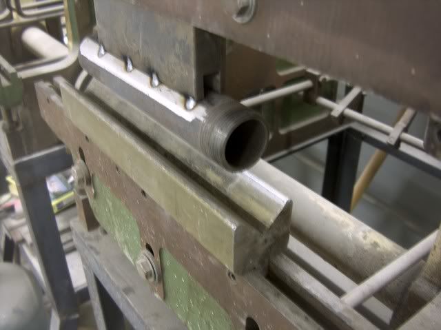
I posted this earlier in this thread for Kevin, perhaps this is what you were looking at...

Looking at the upper die, it is an acute lower die that has been (factory??) modified with the addition of an "extension kit". You can see in the following pictures that the radius can easily be changed by using a different rod. (My brake with this die came out of a trophy shop in NJ....so one can surmise they were using it on lighter guage aluminum)


The lower die consists of two half shafts that rest on a machined bed. The "clips" at the end keep the shafts together, it is spring loaded to keep them flat while not in use.


And as is seen in the next pictures, the theory is for the lower shafts to rotate around the top die, for hopefully less die marking of the work piece. May be why this was in a trophy shop.


aggierailroad
Well-known member
Hmm, yep. That's exactly what I've seen.
I got a quote back for less than 50 bucks, including powder coat for one from one shop.
$75 each, ten minimum plus $1,500 tooling fee. Wow.
I'm still leaning towards a pipe and a hydraulic press. I can make a template for the ID to determine bend limits.
I got a quote back for less than 50 bucks, including powder coat for one from one shop.
$75 each, ten minimum plus $1,500 tooling fee. Wow.
I'm still leaning towards a pipe and a hydraulic press. I can make a template for the ID to determine bend limits.
You have truly inspired me and I thank you so much for all the years of knowledge you have shared with the me and this community.
I am a novice and learned so much from you and the others on this thread.
I am presently reading the whole thread for the second time in more detail while practicing the techniques you have shared.
I have some, but little welding and restoration experience, although much has been "hack" after reading your posts.
If you could be so kind to answer some questions. I have for an upcoming patch panel repair --both truck wheel arches ---where i won't be able to reach the welds after welding---that is of upmost concern ----
I believe in your posts you said that you would apply epoxy primer, only of course after rust is removed from the back side ---never to be reached after panel is on ---
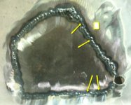
I have included a picture of the back side of a practice patch weld.
1. Note the arrows how the weld did not bead. Would this cause early failure(from the front it looked perfect)?
2. I am confused---i keep reading to apply short strand fiberglass filler over the front side welds...regardless of how it looks ----however now that i have been welding via your methods the front side looks perfect, and on occasion i may see a small seam area. If you have a small seam area do you reweld it or how would you address it?
3. At times on trimming panels i am reluctant to make a gap between the panels because i am more likely to blow through. Do you ever weld two panels together if they touch at the ****--or do you always create a space ?
Any other feedback that you may have is deeply appreciated.
Humbly appreciated,
Bill
I am a novice and learned so much from you and the others on this thread.
I am presently reading the whole thread for the second time in more detail while practicing the techniques you have shared.
I have some, but little welding and restoration experience, although much has been "hack" after reading your posts.
If you could be so kind to answer some questions. I have for an upcoming patch panel repair --both truck wheel arches ---where i won't be able to reach the welds after welding---that is of upmost concern ----
I believe in your posts you said that you would apply epoxy primer, only of course after rust is removed from the back side ---never to be reached after panel is on ---
I have included a picture of the back side of a practice patch weld.
1. Note the arrows how the weld did not bead. Would this cause early failure(from the front it looked perfect)?
2. I am confused---i keep reading to apply short strand fiberglass filler over the front side welds...regardless of how it looks ----however now that i have been welding via your methods the front side looks perfect, and on occasion i may see a small seam area. If you have a small seam area do you reweld it or how would you address it?
3. At times on trimming panels i am reluctant to make a gap between the panels because i am more likely to blow through. Do you ever weld two panels together if they touch at the ****--or do you always create a space ?
Any other feedback that you may have is deeply appreciated.
Humbly appreciated,
Bill
Attachments
Bill, thanks for the questions, responses in blue..
You have truly inspired me and I thank you so much for all the years of knowledge you have shared with the me and this community.
I am a novice and learned so much from you and the others on this thread.
I am presently reading the whole thread for the second time in more detail while practicing the techniques you have shared.
I have some, but little welding and restoration experience, although much has been "hack" after reading your posts.
If you could be so kind to answer some questions. I have for an upcoming patch panel repair --both truck wheel arches ---where i won't be able to reach the welds after welding---that is of upmost concern ----
I believe in your posts you said that you would apply epoxy primer, only of course after rust is removed from the back side ---never to be reached after panel is on ---
I have included a picture of the back side of a practice patch weld.
1. Note the arrows how the weld did not bead. Would this cause early failure(from the front it looked perfect)?
The visible "seam" on the back side shows a bit too much for my liking, if you only had a few sporadic spots, it may be a different story.
This shows insufficient weld penetration, where a slight bit more heat would eliminate that issue. Additionally, you have some weld spots that do show weld penetration through the back side, these weld dots appear to be larger in diameter where you sat on the trigger a bit longer. I would suggest to work on your consistency a bit more. A little more heat would give you the weld penetration needed, and a bit less time on the trigger would better limit the size of the weld dot for less clean up. You need to find that happy medium and work to stay in that "zone". You're not that far from being there, btw.
2. I am confused---i keep reading to apply short strand fiberglass filler over the front side welds...regardless of how it looks ----however now that i have been welding via your methods the front side looks perfect, and on occasion i may see a small seam area. If you have a small seam area do you reweld it or how would you address it?
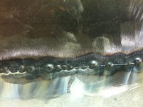
This is very similar to a question I've been asked before. Basically I see fiberglass filler as a Band-Aid to fix weld deficiencies. If the welds are experiencing pin holes, gaps, insufficient welds, or other defects, work to fix the weld issues in the welding stage. For example, here is a picture I pulled off the web that shows insufficient weld penetration.

This would likely be another case where your "resource" that you read from would indicate to use fiberglass filler. The weld penetration is poor at best and the mindset is to use fiberglass filler to add strength that is sorely lacking otherwise. To grind down any weld proud, as we should, it would remove much of the weld strength as it is sitting on top of the panel. I would say that this is an unacceptable repair that will be short lived, and should be redone. This is why I have always stressed to set your welder first and foremost for a full penetration weld, then increase the feed speed to eliminate any blowout (if needed), and fine tune from there. Practice on pieces of scrap the same thickness as your body panels to insure your welder is properly set up before starting on the good panels. I would also say that you should look for alternate resources that don't propose using fiberglass filler over welds. The welds should stand on their own, or work to fix the WELD problems.
3. At times on trimming panels i am reluctant to make a gap between the panels because i am more likely to blow through. Do you ever weld two panels together if they touch at the ****--or do you always create a space ?
Given adequate weld penetration, there is no reason you shouldn't **** the seams tightly together. Any time you leave a gap you also increase the likelihood that any shrinking will pull the panels closer together, resulting in the need for more planishing, or more filler, depending on your finishing methods. Consistency in your methods will go far in weld improvement
Any other feedback that you may have is deeply appreciated.
Humbly appreciated,
Bill
Bill, this may help to clarify the process I use for welding in patches:
http://www.garagejournal.com/forum/showpost.php?p=4431232&postcount=388
And for that matter, the entire thread would be a good read for you....
http://www.garagejournal.com/forum/showthread.php?t=53534
http://www.garagejournal.com/forum/showpost.php?p=4431232&postcount=388
And for that matter, the entire thread would be a good read for you....
http://www.garagejournal.com/forum/showthread.php?t=53534
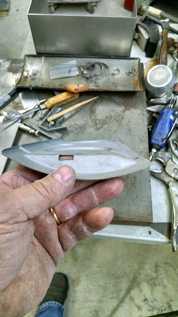
Well I'm back from UK, Kyle is still plugging away on stainless polishing and repairs..
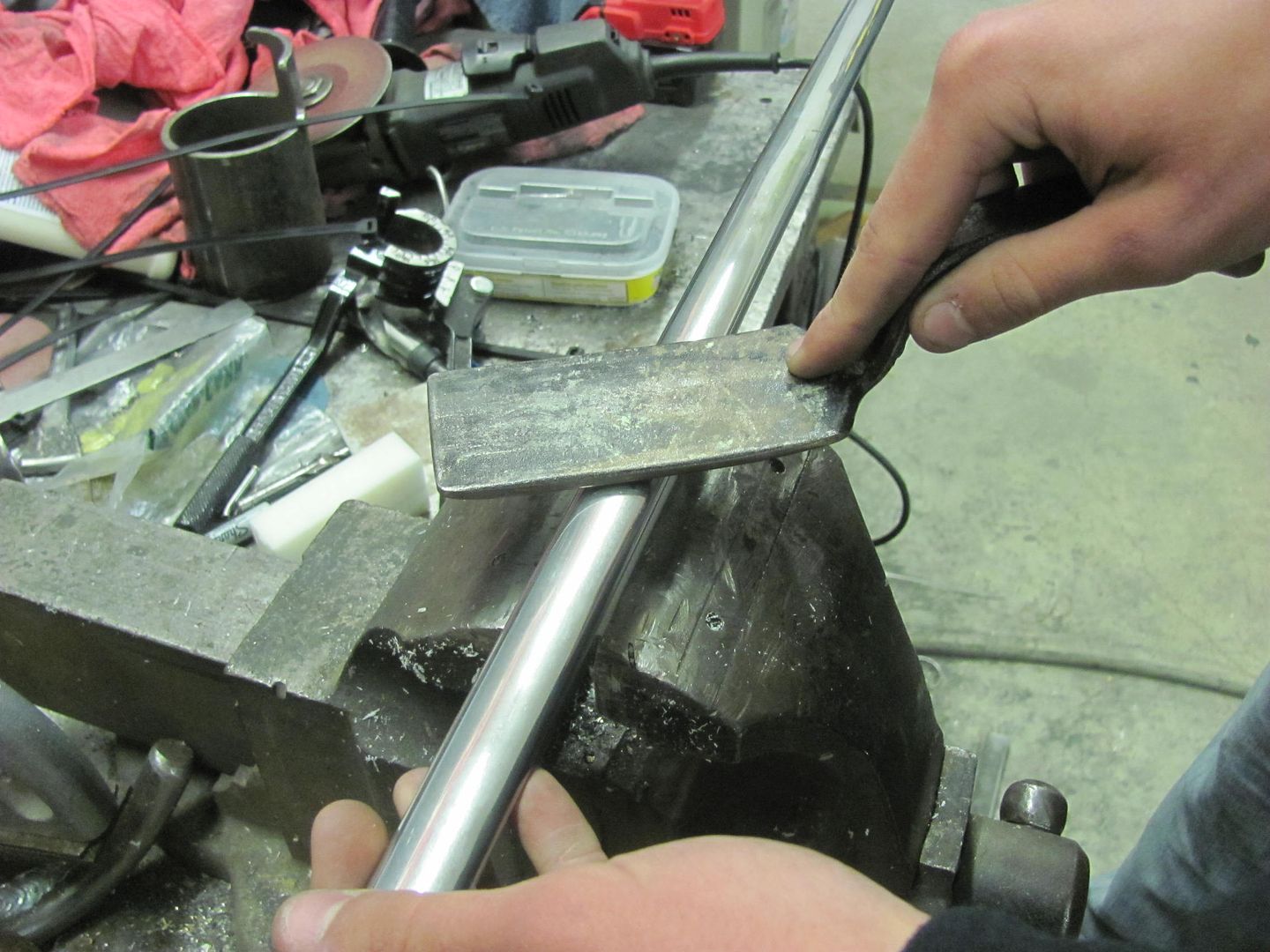
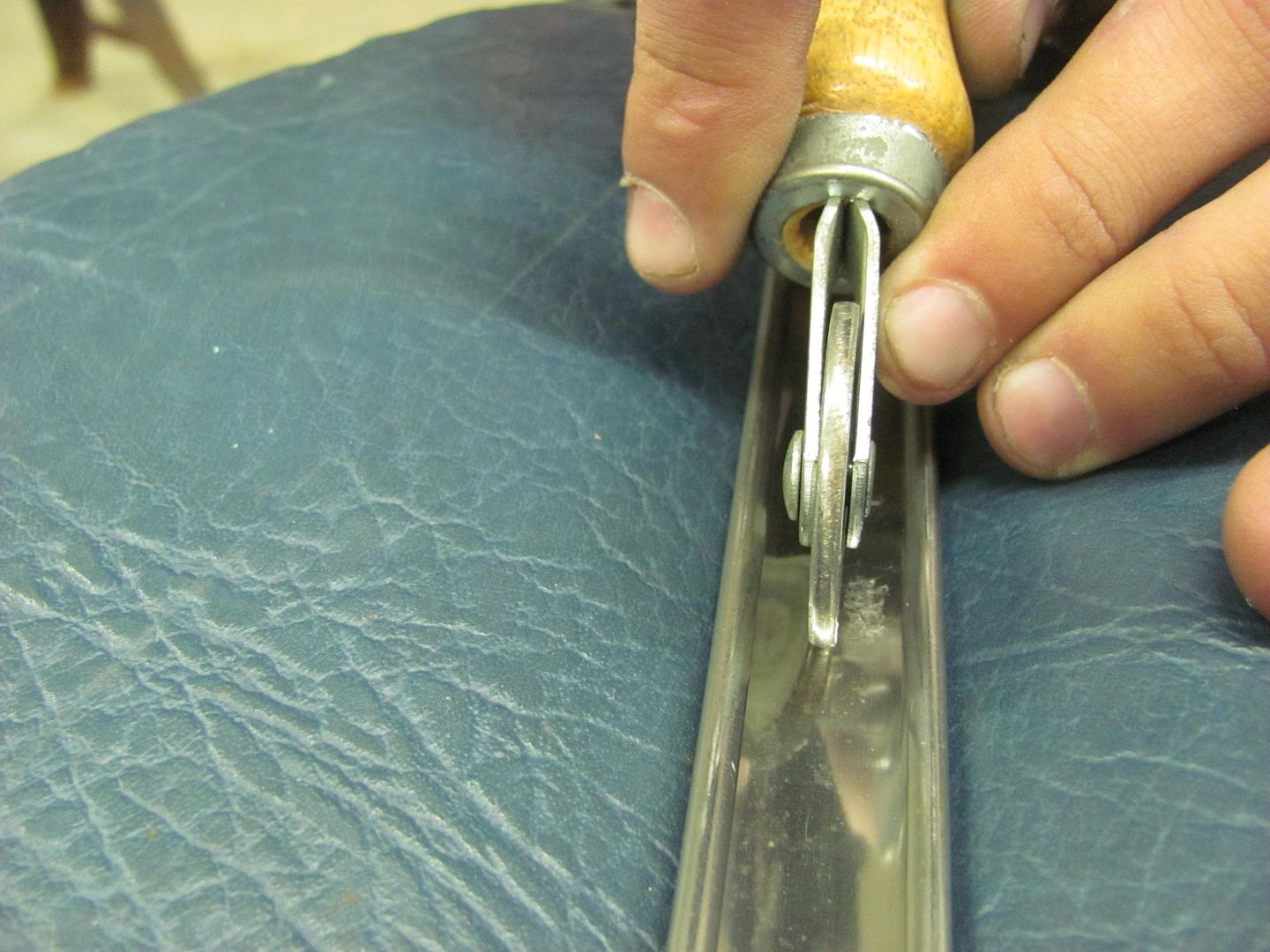
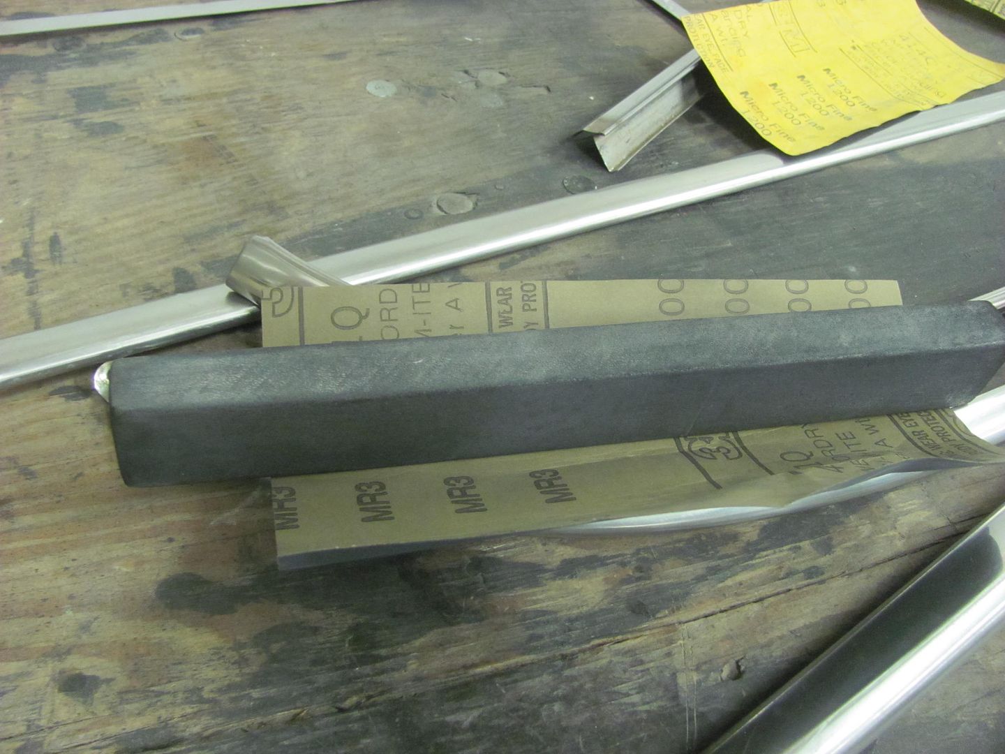
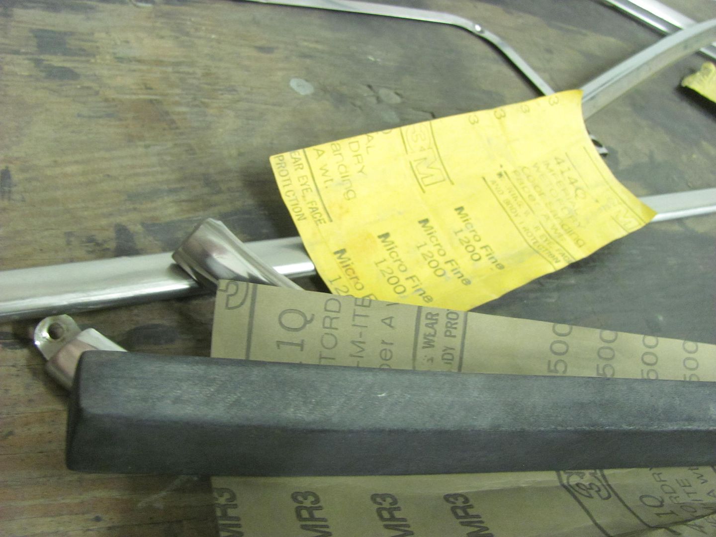
Here's just a few of the implements used. And I must stress, this is not an 18 ga panel, with stainless trim we use light taps for everything.
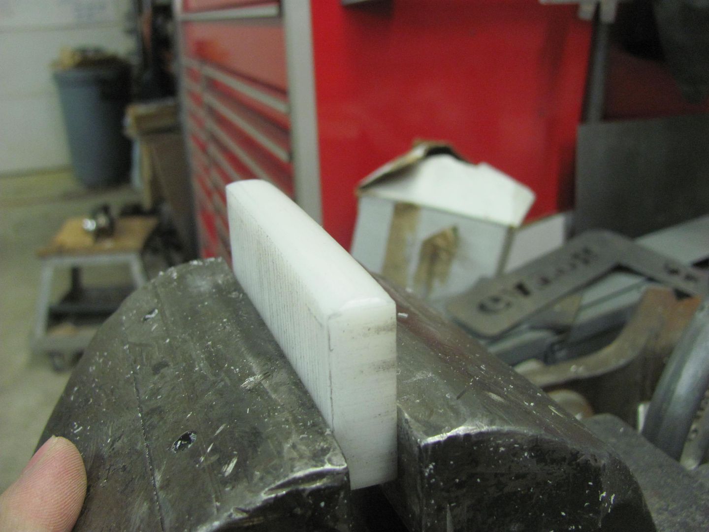
Here's a piece of Delrin that was cut out and filed to match the bottom side of the door trim to act as a soft "anvil".
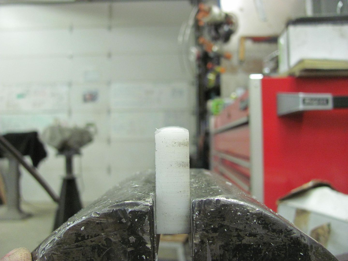
Then a spoon is used to bump.... LIGHTLY
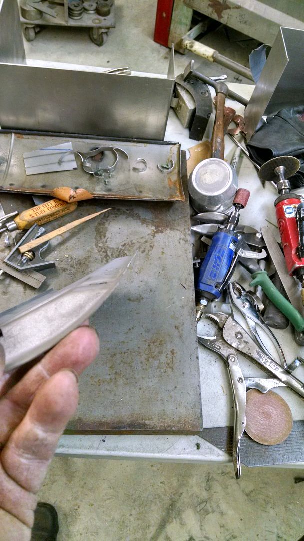
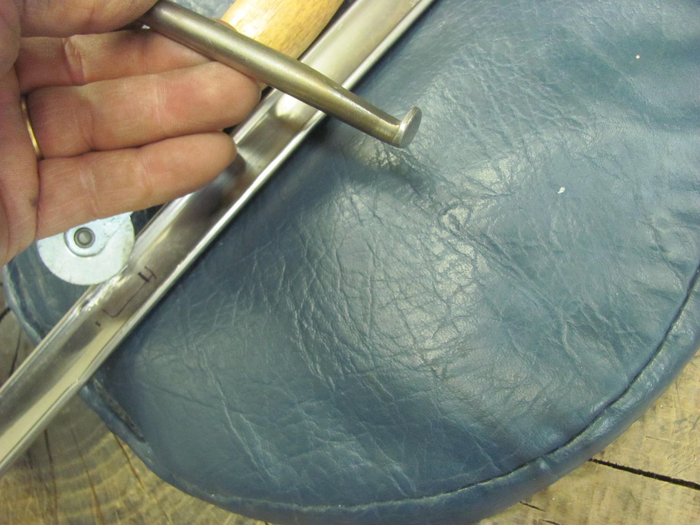
Many ways of bringing up low spots, here are just a couple of the tools used...
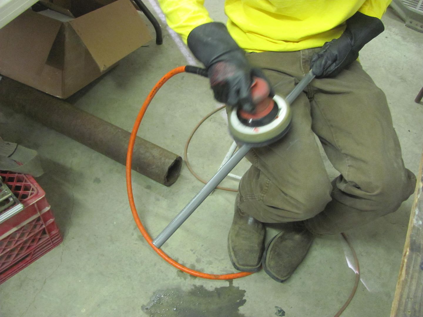
This is a roller tool used for installing the "beading" to hold in screen material. The roller has been flattened from the original version, which had a hollow in the middle. A 3" roloc sander held just right will get the wheel spinning while sanding it flat..
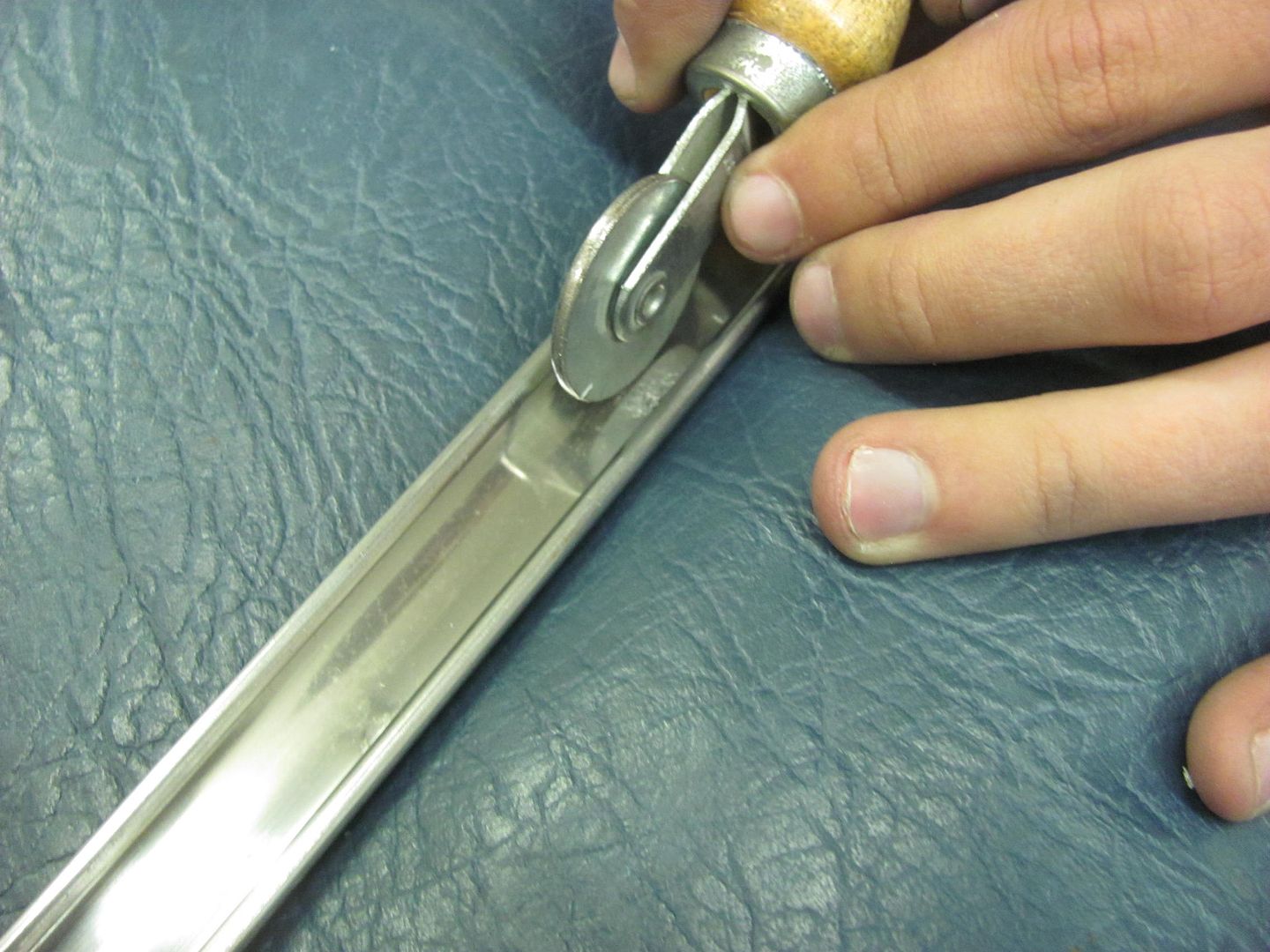
In many cases you'll bump the highs down, roll the lows out, and check your progress using the fluorescent light tube reflections, and repeat. It is not likely this is a one and done process.
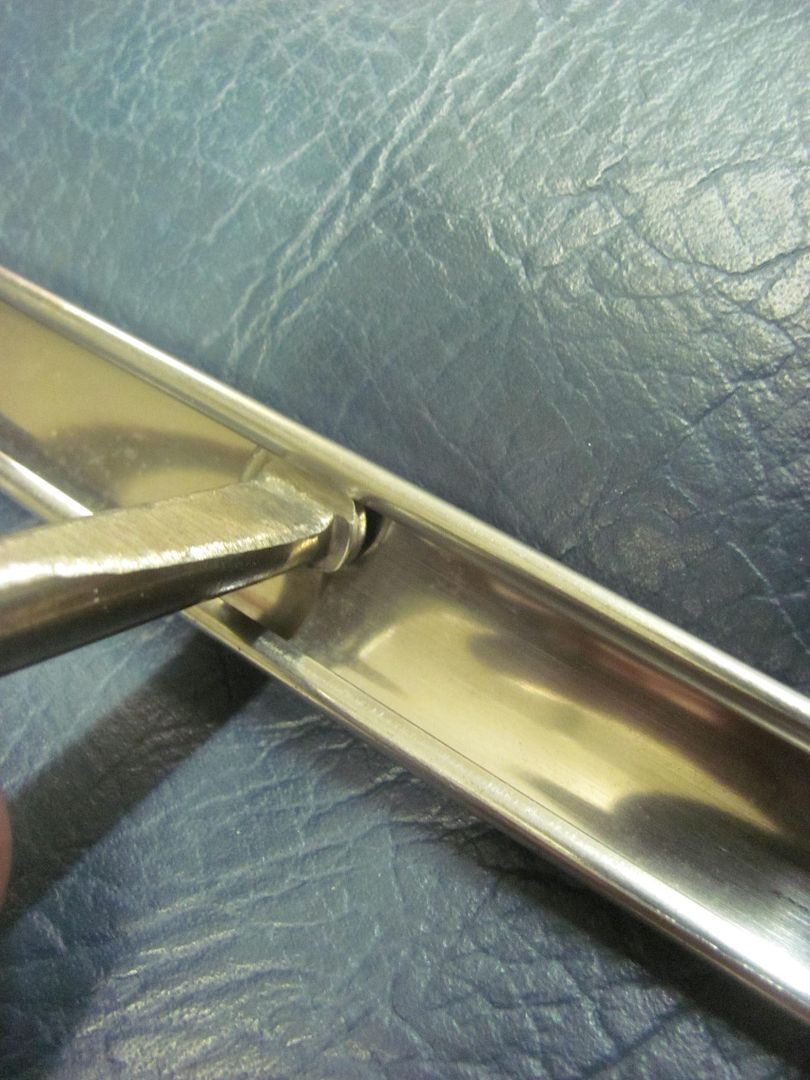
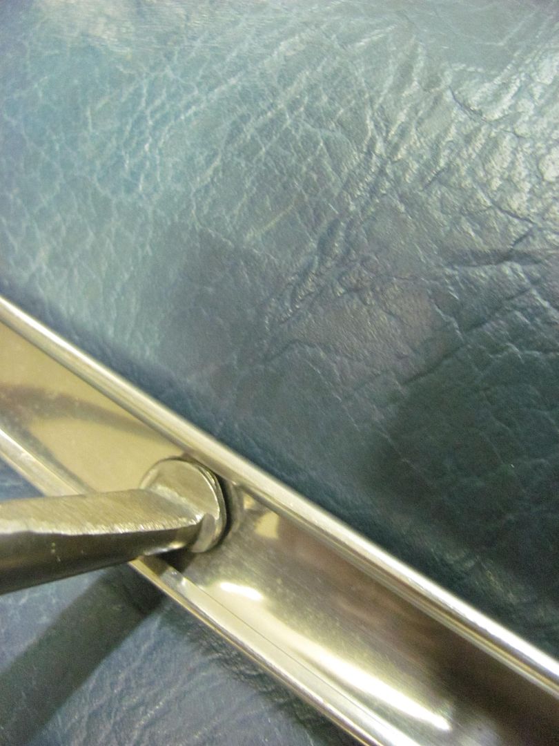
Another tool that can sneak in behind flanges.
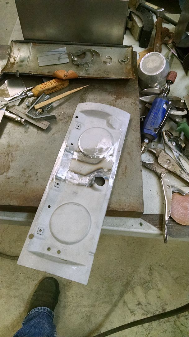
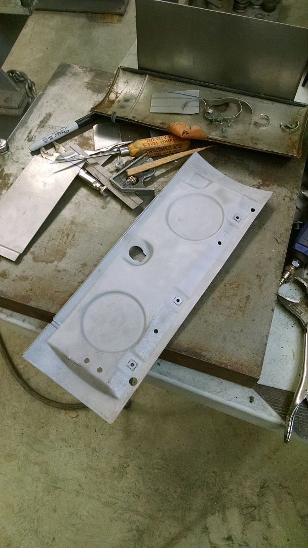
Also used some dry sanding with the durablock, here using 500 then 1200 paper.
Then followed with the Trizact 1500, then 3000. Then it should be ready for the buffer..
Here's just a few of the implements used. And I must stress, this is not an 18 ga panel, with stainless trim we use light taps for everything.
Here's a piece of Delrin that was cut out and filed to match the bottom side of the door trim to act as a soft "anvil".
Then a spoon is used to bump.... LIGHTLY
Many ways of bringing up low spots, here are just a couple of the tools used...
This is a roller tool used for installing the "beading" to hold in screen material. The roller has been flattened from the original version, which had a hollow in the middle. A 3" roloc sander held just right will get the wheel spinning while sanding it flat..
In many cases you'll bump the highs down, roll the lows out, and check your progress using the fluorescent light tube reflections, and repeat. It is not likely this is a one and done process.
Another tool that can sneak in behind flanges.
Also used some dry sanding with the durablock, here using 500 then 1200 paper.
Then followed with the Trizact 1500, then 3000. Then it should be ready for the buffer..
This shows insufficient weld penetration, where a slight bit more heat would eliminate that issue. Additionally, you have some weld spots that do show weld penetration through the back side, these weld dots appear to be larger in diameter where you sat on the trigger a bit longer. I would suggest to work on your consistency a bit more. A little more heat would give you the weld penetration needed, and a bit less time on the trigger would better limit the size of the weld dot for less clean up. You need to find that happy medium and work to stay in that "zone". You're not that far from being there, btw.
I practiced today with your advice----you were spot on ----i turned up the heat and way better weld penetration in addition to the welds on the front side not standing high. I still need further improvements with trigger timing.
Given adequate weld penetration, there is no reason you shouldn't **** the seams tightly together. Any time you leave a gap you also increase the likelihood that any shrinking will pull the panels closer together, resulting in the need for more planishing, or more filler, depending on your finishing methods. Consistency in your methods will go far in weld improvement
Question ----with this in mind----if I am welding a long seam over the wheel arch where i will not be able to planish due to limited access---in your view will I have less risk of warping the panel if i leave a ---say a 1/16" or less gap or if i do my best to fit the panel metal to metal with no gap? I'm taking into account the methods/process that you have taught me minus the planishing.
Thank you,
Bill
Bill, where many will say to use only as much of the replacement panel to fix the rust issues, I have suggested to look instead to where the seam would provide better access for planishing the weld. So if the entire panel puts the seam into a more accessible location, use all you can. If removing the wheel tub gives better access, then remove it, make the repair, and reinstall the tub. Perhaps a second person's assistance would make the difference, or a modified dolly with a long "arm".
As far as the gap vs. no gap, the weld and Haz is going to shrink. With a gap between the two pieces it will pull together even more readily, giving you a nice loose oil can to contend with, with even more work at planishing to try and remove this defect. Trim accurately, no gap, and you should have less work ahead of you.
If you haven't read the patch panel thread that I linked, I would suggest doing so before starting on your repair, it may clear up quite a bit.
shortykorte
Well-known member
Well I'm off to read about patch panels. Thank you for taking the time to teach. This weekend I made my first sheet metal part. I was going to make a wood mold and press the part but for my needs, a brake and using the original bed shape and a couple of hammers I made the part. This fits under an opening of a truck bed access hatch.
Attachments

green7racer
Active member
Sorry to hijack this thread but I need advice on how to fit door skins to a door frame without needing heat to eliminate oil canning.
My old Triumph TR6 had been restored prior to my buying it and it looks like the restorer replaced both door skins and then used a torch to spot heat just about the whole skin surface to shrink the metal.
Seems that the heat or the actual flame has embedded some sort of impurities into the metal which then creates, over time, cracking of the paint substrates which show through the surface. UGLY!
I'd appreciate any advice as I'm going to either get the skins replaced again or just stump up for complete shells.
Mark