To avoid these ads, REGISTER NOW!

MP&C Shop Projects

BORING HOP YARD

Well-known member
Joined
Jan 13, 2007
Messages
1,098
Location
Boring Oregon
Happy Friday MP&C

I have a question if I may seek your advice.
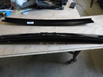
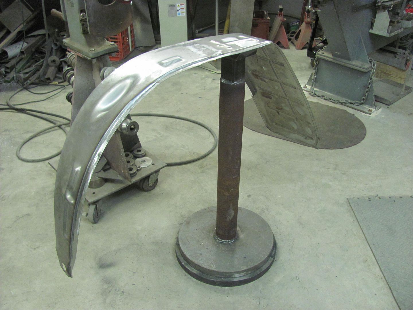
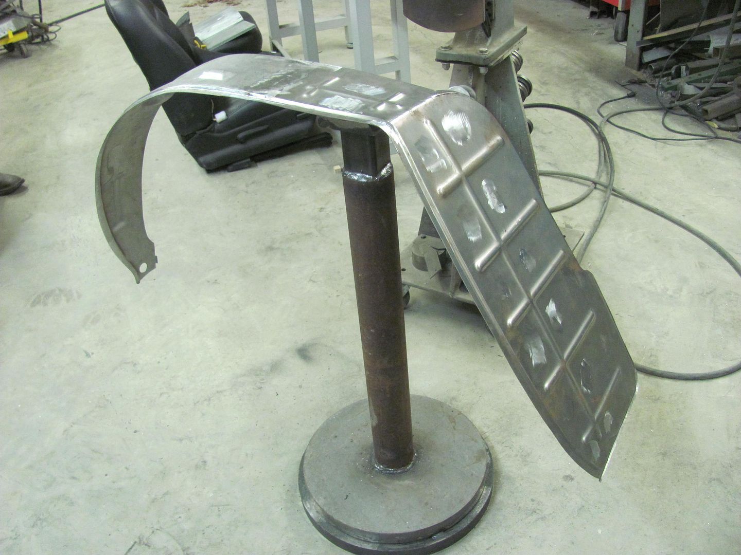
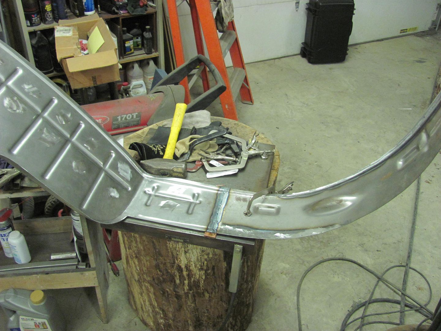
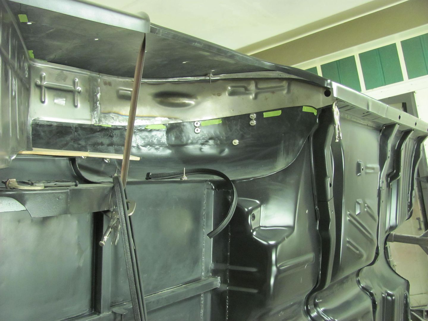
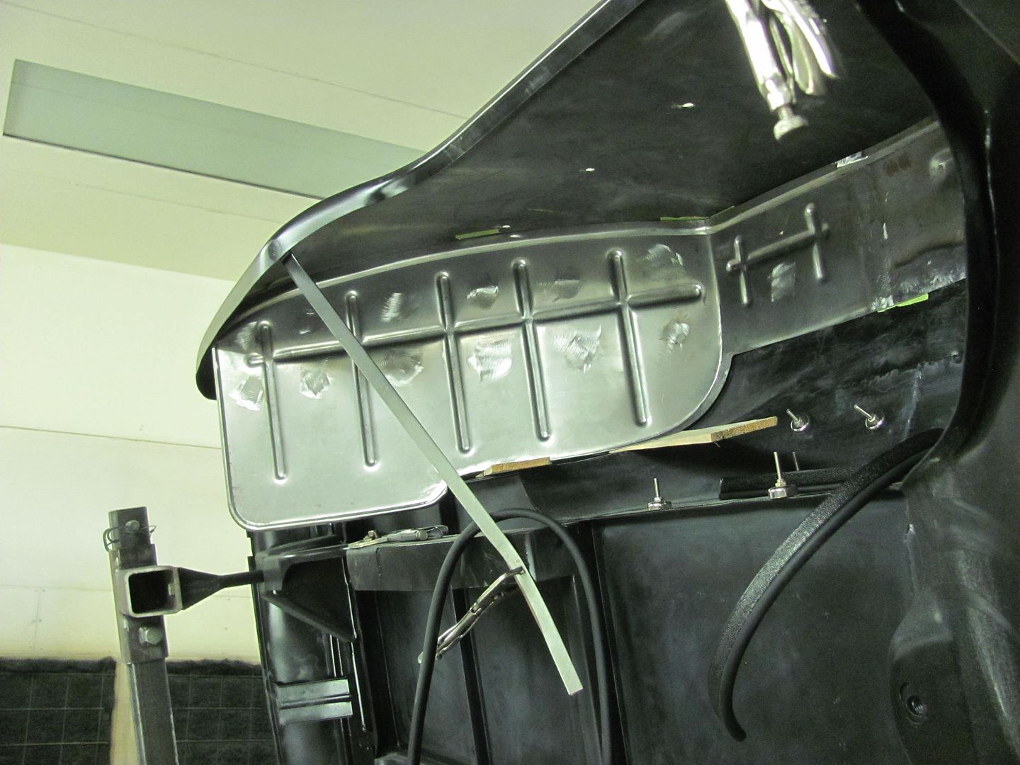
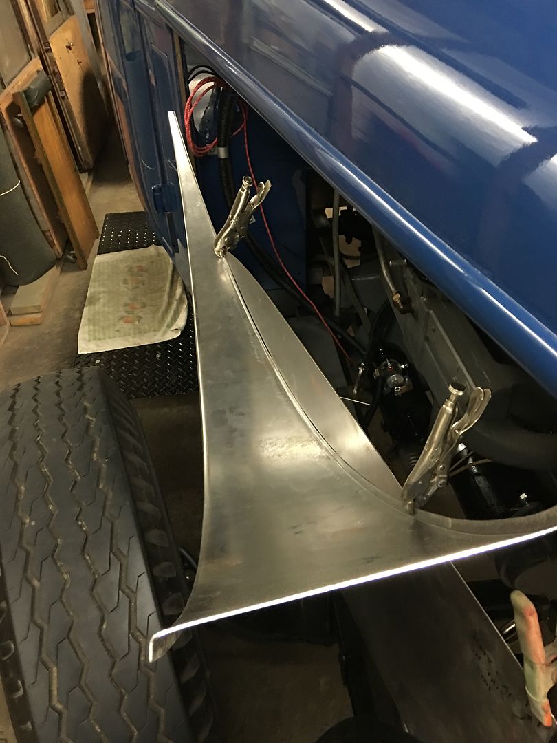
I’m working on a 56 ford f-100 hood.
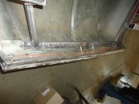
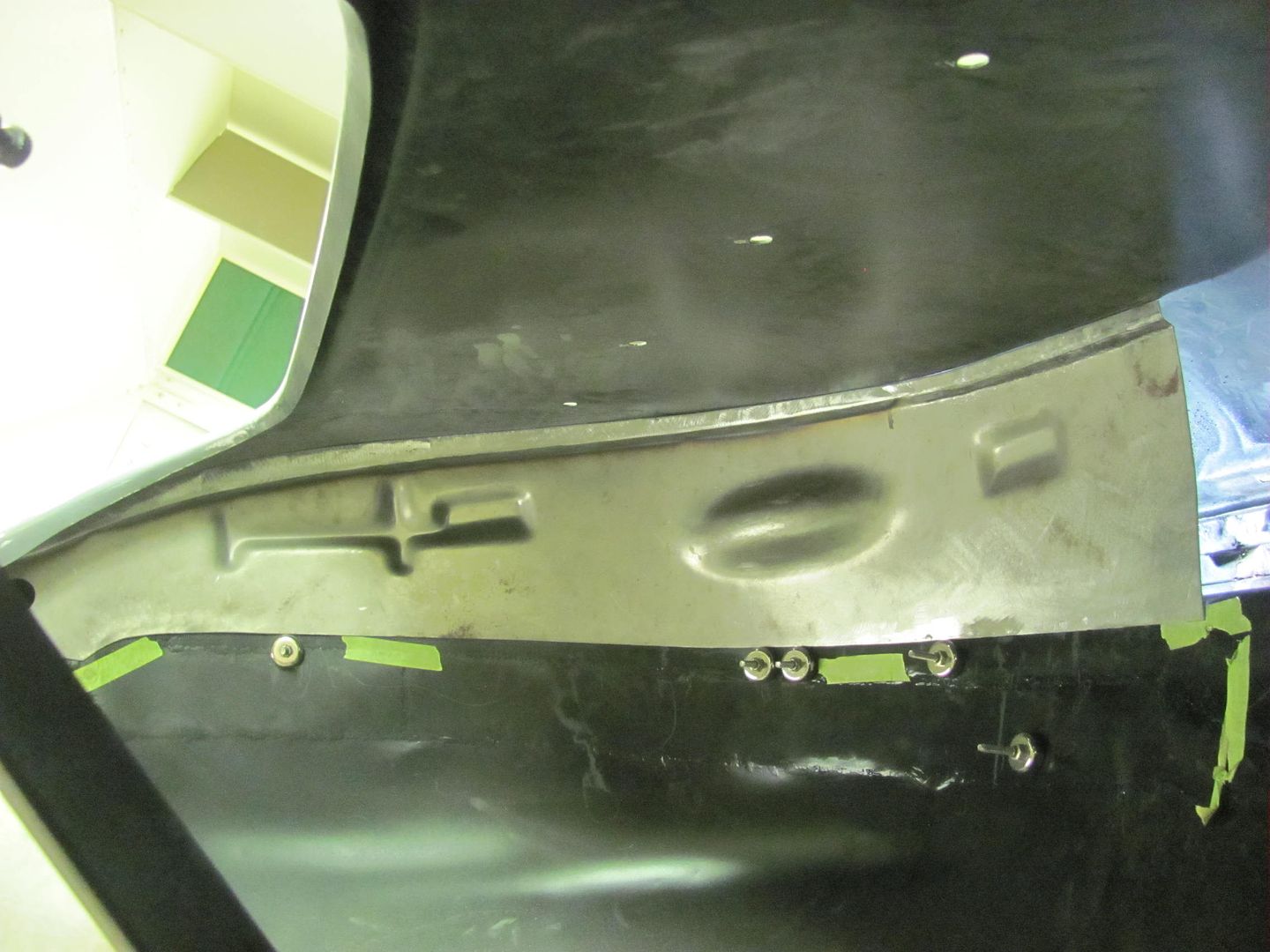
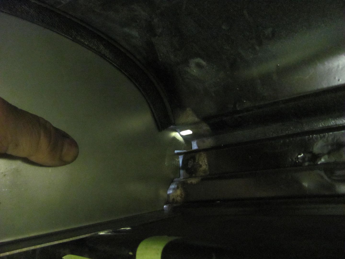
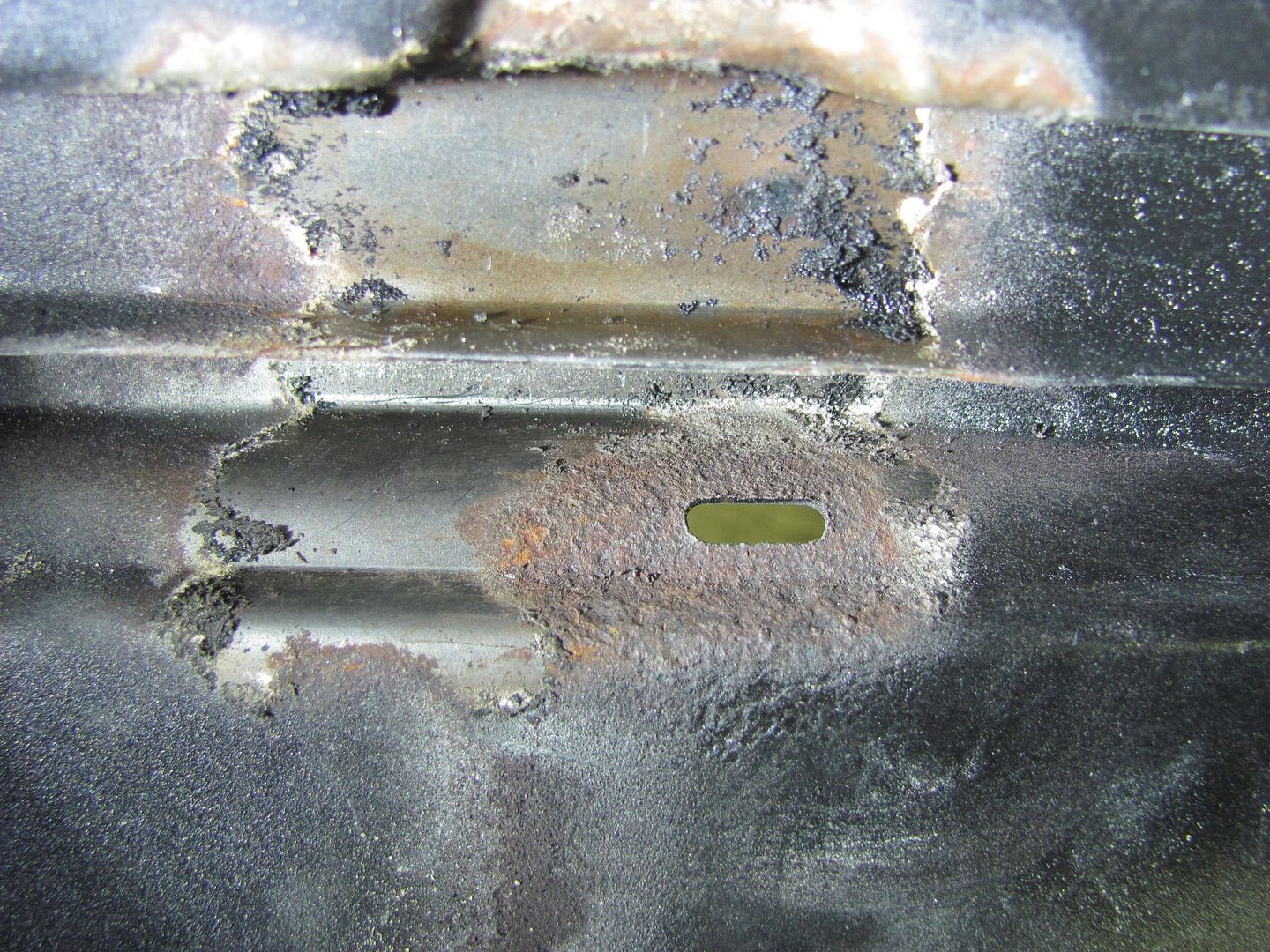
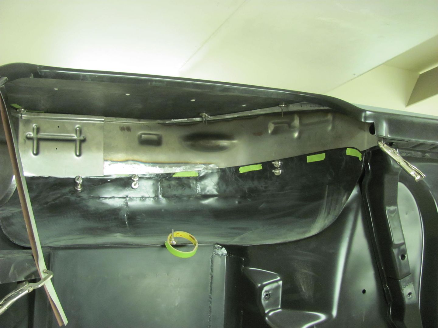
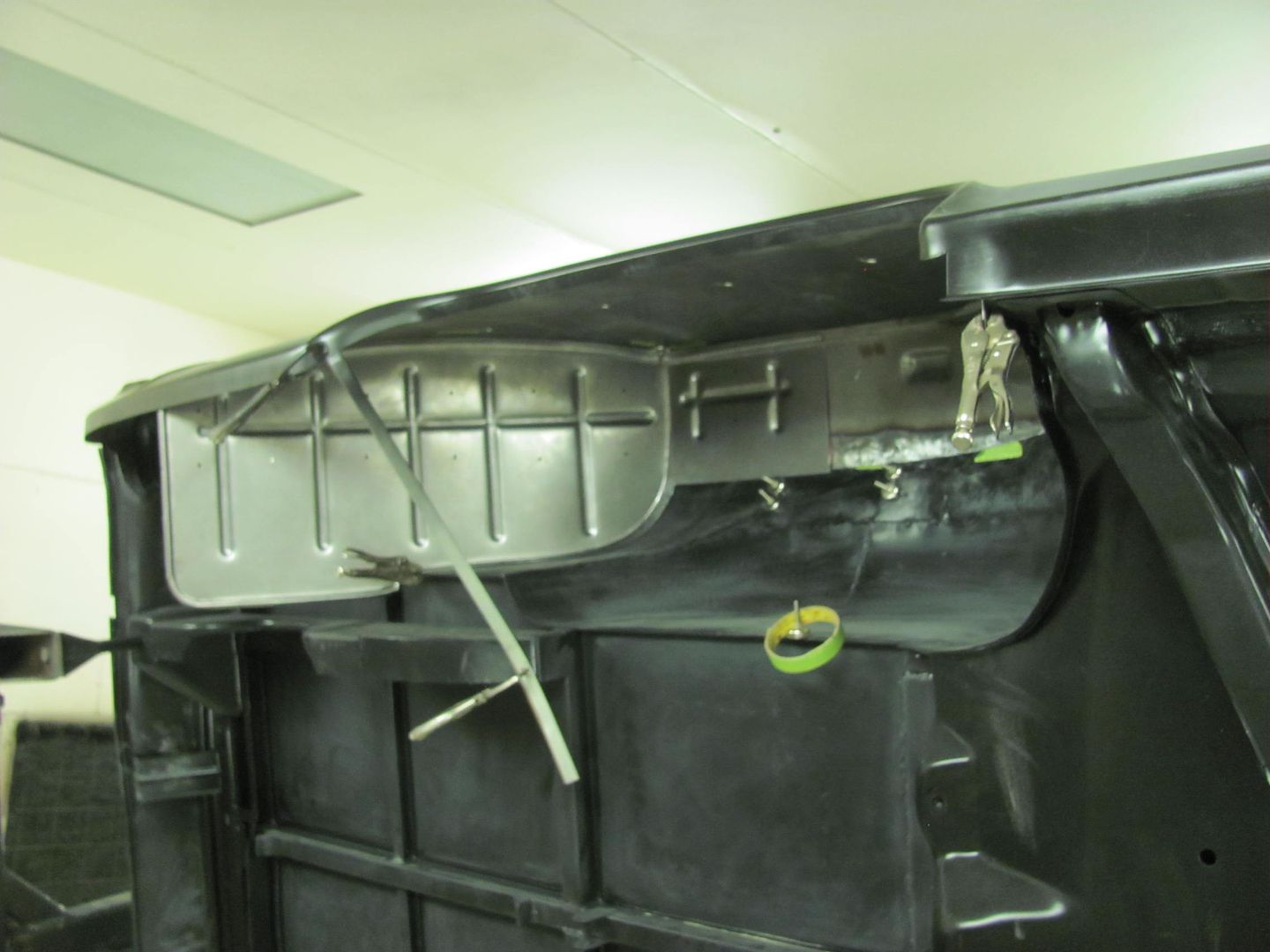
The nose of the hood had cancer and has small metal sections cut out and replaced. These small sections were lap welded and it looks like ****, it’s something you would never see. The structure behind the skin has cancer and needs to be replaced.
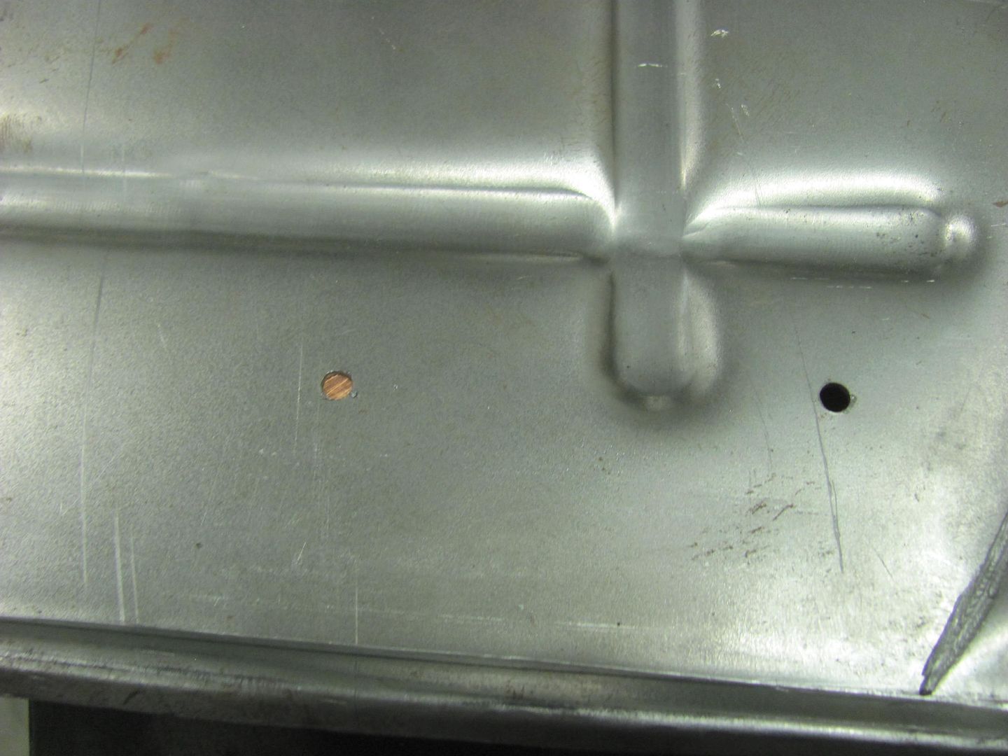
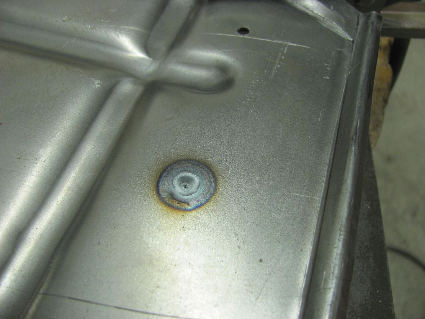
I have both Reproduction replacement parts to make the repair.
“My question is” which part would recommend the I replace first?
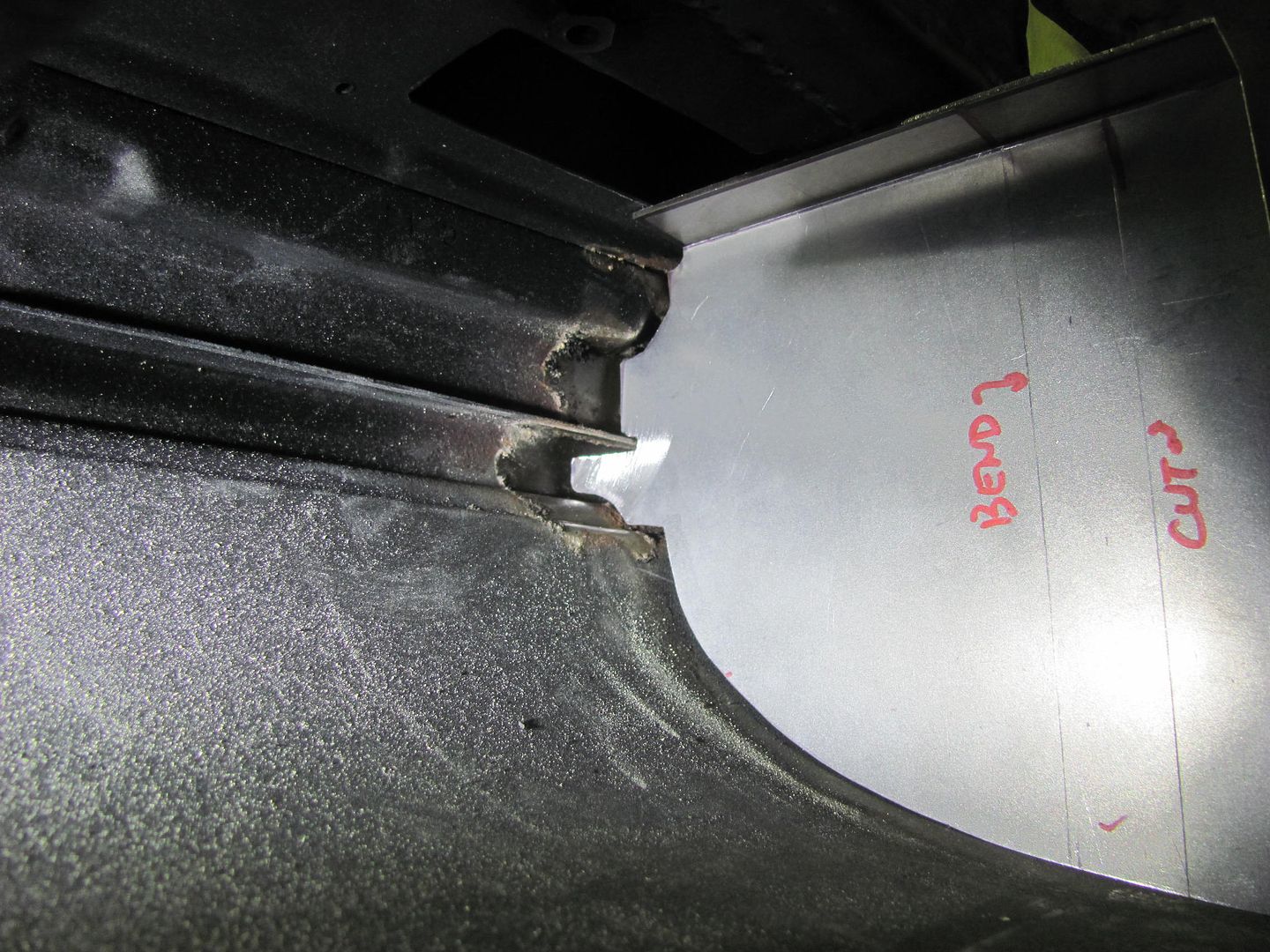
The inner structure would seem to me to be the starting point; I should be able to use the skin as a locator. Then remove the skin and use the inner structure to locate the skin. I would also like your opinion if you would weld a reinforcements to make sure the hood doesn’t tweak, anybody know if these hoods are under stress that comes out when the structure is removed?
Thank you!
 
To avoid these ads, REGISTER NOW!
OP
M

MP&C

Well-known member
Joined
Oct 21, 2009
Messages
4,396
Location
Leonardtown, MD
Given the outside is a mismosh of warpage (likely) I would prefer to cut that out and keep the inner intact for locating purpose. Then weld in the new. Of course this is said without having pictures or the actual part in front of me. It may be better to cut all of it off and have the hood bolted up to the truck so as to use the adjacent panels for alignment. but I would think it easier to planish all the outer skin welds with the inner out of the way if you could still get the inner part in place afterward. There. Now I've totally confused the issue. :thumbup:
 
OP
M

MP&C

Well-known member
Joined
Oct 21, 2009
Messages
4,396
Location
Leonardtown, MD
Greg, I missed part of your question. Anytime a panel is pressed, i.e. a door skin, a roof skin, a hood skin, etc, part of the shape that is pressed in there helps to support the panel. Like the arch described in a post above. Take the keystone out of an arch and you no longer have the support. Cut the bottom 10" off a door skin and the what's left will flatten out. If you go back in this thread and look at the roof repair, I added some bracing to help support the roof to limit this flattening effect. So yes, the shape preformed at the factory in a gimormous press supports that panel. Any cut will affect those inherent stresses in the panel where you'll need to address them in your fitment, trimming, welding, and planishing.
 
Last edited:
OP
M

MP&C

Well-known member
Joined
Oct 21, 2009
Messages
4,396
Location
Leonardtown, MD
Greg, if you were to weld the outer portion in first, is it still possible to install the inner brace after the fact?
 
OP
M

MP&C

Well-known member
Joined
Oct 21, 2009
Messages
4,396
Location
Leonardtown, MD
Finishing up on our drivers side wheel well today. The front "modified" reproduction is trimmed and fitted. A light is put behind it to check for gaps...


Picture%204848.jpg


The baffle that sits above the wheel well is made differently as well, this time using a piece of 16 ga cold rolled steel, and trimmed to fill the void. We left a slight gap that we plan on sealing with seam sealer.


Picture%204851.jpg


Shown here with bulb seal against the quarter....


Picture%204850.jpg


The trouble with the factory version of sealing above the baffle is that the expanding foam encapsulates the surrounding area, to include surrounding the slot for trim hardware. It is here that water intrudes, and is held against the quarter causing rust.


Picture%204853.jpg


Our version will leave this hole unobstructed so that any water intrusion that may occur will pass on through.


Now to fill in our screw holes that held together the "MDF Sandwich" that we used for beading the panel. A piece of 1/4" thick X 1" copper flat bar is used as a backer, I find it leaves the back side of the weld much cleaner than using flattened copper pipe.


Picture%204855.jpg


Picture%204856.jpg


Video version:


Picture%204857.jpg


With the front and rear sections having been fitted and trimmed for a **** weld, next we tack the panels together with the TIG..


Picture%204858.jpg


Picture%204859.jpg


Picture%204860.jpg


Now we have a one piece wheel well, no overlap joints to trap moisture and start rust, as the originals had done.


Picture%204861.jpg


Picture%204862.jpg


One piece wheel well test fitted using the bulb seal....


Moving on to the passenger side, both front and back are trimmed and test fitted. Some minor tweaks and we will be ready to trim for a **** weld and TIG these together next time..


Picture%204863.jpg


Picture%204864.jpg
 

BORING HOP YARD

Well-known member
Joined
Jan 13, 2007
Messages
1,098
Location
Boring Oregon
Good morning Robert
The inner can support be remove after the skin is removed and replaced.

Here is what I have done so far. I added 3 braces to hold the skin from moving. I have also cut and fit the skin patch panel and its ready to weld.
My plan for today is to tig weld the skin, remove the inner brace, planishing the area "hopefully not too much" install new inner bracket and if all goes well have a beer thirty moment or 2.
stay tuned!
Thank you for your advice!
 

yaidunno

Well-known member
Joined
Feb 10, 2011
Messages
1,336
Location
WI
Robert, I might have missed it, but does your TIG welder have a pulse function? It does an excellent job with allowing you to run a continuous bead, and not distort the panel.

Great looking pieces as always, and thanks for sharing!

-Bryan
 

TRS63

Well-known member
Joined
Aug 5, 2011
Messages
128
Location
Stuttgart, Germany
Wow, top notch work! Really inspiring!
I am in the process of buying an english wheel to complete my metalshaping tools and really have everything to dive deep into the restauration of my old VWs. Now, after reading your last posts, I have a question. I was always told that a mig is what should be use to weld the body of a car (patch, small holes,...) and that's what I used until now. But if I read you well, a TIG would be better/would require less work "after welding"?
Thanks
Antoine
 

andsonsvd

Well-known member
Joined
Feb 7, 2012
Messages
169
Location
Mandurah, Western Australia
Robert,

Firstly I have a bone to pick with you, I am currently SO far behind on my work because I spent half the last week at work reading the 105 pages. Haha Mate I really appreciate all of your work putting this together.

I have a question from the Guru please.

I am building a 1948 Chev Truck and the rear panel is very damaged and oil canned. I am a novice metal worker, and was wondering would it be easier and stronger to replicate the pack panel of a later truck like below.

Thanks again Mate you do awesome work!!

Cheers from down under.
Shane
 

Attachments

  • photo 1-1.jpg
    photo 1-1.jpg
    70.4 KB · Views: 104
  • 1219100608.jpg
    1219100608.jpg
    59.1 KB · Views: 100
OP
M

MP&C

Well-known member
Joined
Oct 21, 2009
Messages
4,396
Location
Leonardtown, MD
Wow, top notch work! Really inspiring!
I am in the process of buying an english wheel to complete my metalshaping tools and really have everything to dive deep into the restauration of my old VWs. Now, after reading your last posts, I have a question. I was always told that a mig is what should be use to weld the body of a car (patch, small holes,...) and that's what I used until now. But if I read you well, a TIG would be better/would require less work "after welding"?
Thanks
Antoine

Very likely this was told to you by someone working on their own project, not a coachbuilder. Can using a MIG work, by all means. Is it more work, many times over.

Accurate trimming of the panels is so much more important using the TIG. If you apply heat and you have a gap it tends to burn back the edges even more.. instead of fusing the joint together. So for the beginner still learning to fit and trim panels, the point and shoot of a MIG tends to be more forgiving with fitment/gap inconsistencies. A bit of practice with the TIG and how much less work it can be is a very good incentive for someone to improve on those trimming and fitment skills, which are very much a big part of the welding process..


Robert,

Firstly I have a bone to pick with you, I am currently SO far behind on my work because I spent half the last week at work reading the 105 pages. Haha Mate I really appreciate all of your work putting this together.

I have a question from the Guru please.

I am building a 1948 Chev Truck and the rear panel is very damaged and oil canned. I am a novice metal worker, and was wondering would it be easier and stronger to replicate the pack panel of a later truck like below.

Thanks again Mate you do awesome work!!

Cheers from down under.
Shane


Shane, unless this is a look you are after, I would find it less work to metal bump/torch shrink the panel back to where it should be. If trying to duplicate the back panel of the newer truck, there is quite a bit of stretch that was added when that part was pressed at the factory. Even though your truck may have some excess metal in the form of oil cans/dents, it is far closer to reverting back to original than the work that will be required to provide enough stretch to add those details. Glad you enjoyed the thread!
 

andsonsvd

Well-known member
Joined
Feb 7, 2012
Messages
169
Location
Mandurah, Western Australia
Hey again Robert,

Thanks for that Ill give that a try.

Also while your giving out your awesome advise, can you please let me know how you would handle this? I have a 1937 Chevrolet Sedan and I am wanting to fit some Rolls Royce style handles for the suicide doors. How do I start to great the handle pockets? Do I just hammer the pockets out of a piece of steel with a hammer and shot bag? Thanks Shane
 

Attachments

  • 2010-rolls-royce-ghost-door-handles.jpg
    2010-rolls-royce-ghost-door-handles.jpg
    46.1 KB · Views: 128
OP
M

MP&C

Well-known member
Joined
Oct 21, 2009
Messages
4,396
Location
Leonardtown, MD
Shane, look up flow forming. I think you could probably accomplish this "void" using an MDF hammer form with an opening in the middle, and a "corking" tool in an air hammer/rivet gun. You would have some holes to fill afterward (the ones to bolt the MDF sandwich together) Definitely would warrant practice on a scrap piece of metal or door..
 
OP
M

MP&C

Well-known member
Joined
Oct 21, 2009
Messages
4,396
Location
Leonardtown, MD
Progress from this past week.. Kyle got started on media blasting the drivers side wheel well and I "assembled" the two components for the passenger side..


Picture%204869.jpg


Picture%204876.jpg


Picture%204877.jpg


We plan on epoxy primer on these prior to installation, so the media blasted surface will give a good bite for the primer.

Here's the test fit of the assembled passenger side wheel well...


Picture%204878.jpg


Picture%204879.jpg


Next, the road trip on Friday.. To preface, a couple weeks ago someone had posted a link showing a Baileigh English wheel on eBay (the big one). In the background was one of the Baileigh power hammers. So I called the contact number in the ad, asked if the hammer was available, which he said yes. He gave me a price, asked for a deposit, and this past Friday was the pick up day. I left the house at 1:45 am, picked up my nephew Chris, and drove to CT. Got it loaded up, made it back to the house by 10 pm, quite a long day. Wait....it's supposed to rain tomorrow, let's unload! So we got it off the trailer and inside by 11. Saturday, after sleeping in, was spent locating a spot for the machine, hooking up power, and trying it out on some scrap metal..


Picture%204882.jpg


Excited to have this additional capability in the shop.
 
To avoid these ads, REGISTER NOW!
OP
M

MP&C

Well-known member
Joined
Oct 21, 2009
Messages
4,396
Location
Leonardtown, MD
Thanks guys!


What will the power hammer do that the pulmax won't? Nice find!


A reciprocating hammer such as the Pullmax is a fixed stroke machine. They will do shaping, but you need to watch clearances lest the impact cause damage to the machine.. A power hammer is a floating head machine that relies much on the mass of the head design and impact, with little concern to the need for clearancing. Given the greater mass of the power hammer, whether planishing or shrinking, it gets the job done quicker.
 
OP
M

MP&C

Well-known member
Joined
Oct 21, 2009
Messages
4,396
Location
Leonardtown, MD
I have never seen a shop with a power hammer (okay, maybe Jesse James) in it, let alone one that looks like it is actually used !

I'm sure you have an English Wheel. How about an Ironworker ?

Have a Tommasini cast wheel, shown earlier in this thread.. Most of what we do is sheet metal, so no ironworker. Running out of room :willy_nil


Nice score Robert!!!!!
Thanks Dave!

It looks like the supports for the Baileigh are also holders for more die heads. It looks like you have a lot of dies to make or buy!


I think they do that on purpose, someone's OCD makes them want to fill those holes, so they can sell more dies.. :lol:
 

iajonesy

Well-known member
Joined
Feb 8, 2009
Messages
2,467
Location
Iowa
Robert, does the power hammer do much the same thing as a planishing hammer, only on a larger scale?

Mike
 
OP
M

MP&C

Well-known member
Joined
Oct 21, 2009
Messages
4,396
Location
Leonardtown, MD
Thanks for the question Mike. The intended purpose of a planishing hammer is to smooth out lumpy panels after blocking/shaping or to help in removing dents and other minor defects. They aren't really designed for SHAPING the metal as most don't have the needed kahunas. But depending on the size of the air motor, some planishing hammers do cross over into some metal shaping, or smaller planishing hammers take a long *** time to get the job done. The power hammer is designed for shaping metal, be that shrinking or stretching, and typically has enough mass to get it done in short order. It's not out of the ordinary to shape with a power hammer and finish with a planishing hammer to remove any shaping "defects".
 

Duke55

Well-known member
Joined
Jan 18, 2013
Messages
370
Location
Utah
Nice score of another tool on my wish list. I am past the "running out of room" stage. Will need to add on before anymore big tools can be added.

Can't wait to see you put it to use.


Sent from my iPhone using Tapatalk
 

xtremek

Well-known member
Joined
Apr 13, 2012
Messages
11,603
Location
St. Johns, Mi
This is one of the coolest, most informational threads on the web. Thanks for the education on the differences between power and planishing hammers
 

TRS63

Well-known member
Joined
Aug 5, 2011
Messages
128
Location
Stuttgart, Germany
Thanks a lot Robert for taking the time answering my question concerning the TIG welding. Now there is one more element on my wish list:thumbup:

Well done with the power hammer, looking forward to see more project using it!

Antoine
 

andsonsvd

Well-known member
Joined
Feb 7, 2012
Messages
169
Location
Mandurah, Western Australia
Hey Robert, Thanks for taking the time to respond. I looked up Flow Forming and couldn't find anything relevant. If one day you find something on it please post it up here thanks in advance.

Shane
 

EdT

Well-known member
Joined
Sep 21, 2010
Messages
1,104
Location
North Georgia
andsonsvd,
If you search for timman technologies you can find some stuff on flow forming. He also sells tools for doing it although they'd be pretty expensive by the time they got to OZ. I have made a lot of parts using this technique with a form to hammer the parts into. It's just a technique for using an air hammer(rivet gun) to form the parts rather that your arm and it's good for making several parts that are identical (or nearly so) w/o a lot of complex tooling and w/o spending your life doing it. PM me if you want more details.
 

Ohmthis

Well-known member
Joined
Jan 20, 2013
Messages
3,000
Location
Outside of Louisville KY
Hey Robert, I've been keeping up, but being a quiet reader. You've been busy around the shop. On tig welding your panels, are you using filler or making an autogenius weld. I've done some small welds (caps on an oil tank) that I welded without filler, that turned out very nice. Would that even be feasible on a panel that size?
 
OP
M

MP&C

Well-known member
Joined
Oct 21, 2009
Messages
4,396
Location
Leonardtown, MD
On the 16 ga fenders, the front gets a flange turned under that supports the fender in the front. The autogenous weld does have a slight bit of undercut which concerned me given the support needed, so filler rod was used. On the cowl repair behind the hood on the wagon, the fit was not as precise as it could have been, so again, used filler there too.. The autogenous weld is ideal for long welds across body panels as it has the least amount of distortion added. When I can get my trimming to yield zero gaps consistently, that would be more of an option. Until then, filler it is.. As I tell Kyle, this is all practice for working on his 57 Ford p/u... :D
 
Last edited:

Ohmthis

Well-known member
Joined
Jan 20, 2013
Messages
3,000
Location
Outside of Louisville KY
I didn't think of the undercut, yes the fit has to be flawless. I had to use a file to get the fit tight and in the end it was more of an experiment than practice. His truck will no doubt be top notch I'm sure. Did you use a copper backing plate on those fenders as well? It seems as though there is something.
 
OP
M

MP&C

Well-known member
Joined
Oct 21, 2009
Messages
4,396
Location
Leonardtown, MD
When the wagon's rear wheel wells were welded, I used the copper on the edge only to prevent blowout at the edge. The part we made was 18 ga, I believe the CARS reproduction front section is 18 ga as well.

Welding the patch panel to the truck fender did not use any backer at all. This was 16 gauge steel.
 
OP
M

MP&C

Well-known member
Joined
Oct 21, 2009
Messages
4,396
Location
Leonardtown, MD
The shop is hosting another Peter Tommasini class this year, one of the items to pass out to the attendees will be some of the rare earth magnets that we use. I just got my delivery in yesterday, these are Cup-26 magnets from Applied Magnets, they have a 65 lb pull. We use them for holding paper patterns to wheel wells during test fit to copper strip for welding backer..


IMG_1760.jpg


We install a csk 10-32 and lock nut to act as a handle, and they are ready to use...


Picture%203240.jpg


Picture%204863.jpg


IMG_1761.jpg


John has been assembling parts of the Biederman truck front end while waiting for the fender completion. He mocked up the hood the other day only to find out it didn't fit the cab as it should.


IMG_1753.jpg


It looks like the cab is wider than the hood, as the radius does not match and it's pushing the hood outward and up....


IMG_1747.jpg


IMG_1748.jpg


IMG_1755.jpg


To explain, this is a 1947 truck that had extensive rust in the cab. He found a cab on a newer truck, 1951 IIRC, that was made by the same company. It now appears the newer replacement cab is slightly wider than the original, so our intended option is to cut a slice from back to almost the front and add a pie slice to push the radius out and the beltline down where it belongs. Looks like an easier option than remaking the hood. Something else to add to the list. Just to make sure the wider cab doesn't affect fender fitment, we also mocked up the lower hood side and clamped the tapered filler panels and took a comparison measurement from the outside edges, front and back.


IMG_1756.jpg


IMG_1757.jpg


IMG_1758.jpg


IMG_1759.jpg


So we have just shy of 3/8 more in the back, or 3/16 pushed outward on each side. I think we can live with that, it likely is well within factory tolerance.. More to come..
 

EdT

Well-known member
Joined
Sep 21, 2010
Messages
1,104
Location
North Georgia
Always an interesting thread. WRT to the hood issue on the truck, it looks like the hood is hinged at the center. If so, could you pull the hinge pin and move the sides down and out 'till the accent line on the body lines up. That would give you a good idea of how far off the hood is from the cab as well as a better feel for how big a deal it will be to massage the existing hood to fit the cab.
 
To avoid these ads, REGISTER NOW!
Top Bottom