To avoid these ads, REGISTER NOW!

MP&C Shop Projects

OP
M

MP&C

Well-known member
Joined
Oct 21, 2009
Messages
4,396
Location
Leonardtown, MD
Kirk, thanks for the kind words... I don't always post pictures of my scrap pile, but consider it to be my learning curve. Trying something and then modifying the approach to get the results needed. Probably the best example of this was the cowl repair we did on the wagon. Our first approach was to use the bead roller even though I knew it needed to be done on the Lennox. I guess I needed that first approach to see how the metal would respond. Even after we made some dies for the Lennox, we had to modify them as well to dial in the shape needed:


MP&C said:
As we found with some of the practice pieces, when you try to shove metal too much into a hole it tends to pull in from the edges, which distorts what you started with.

Picture%204501.jpg


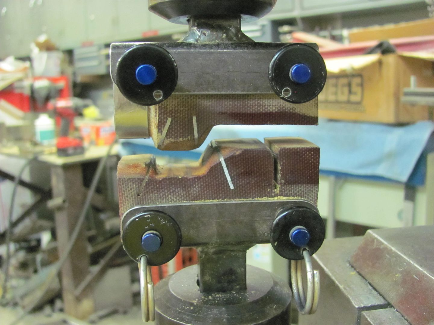
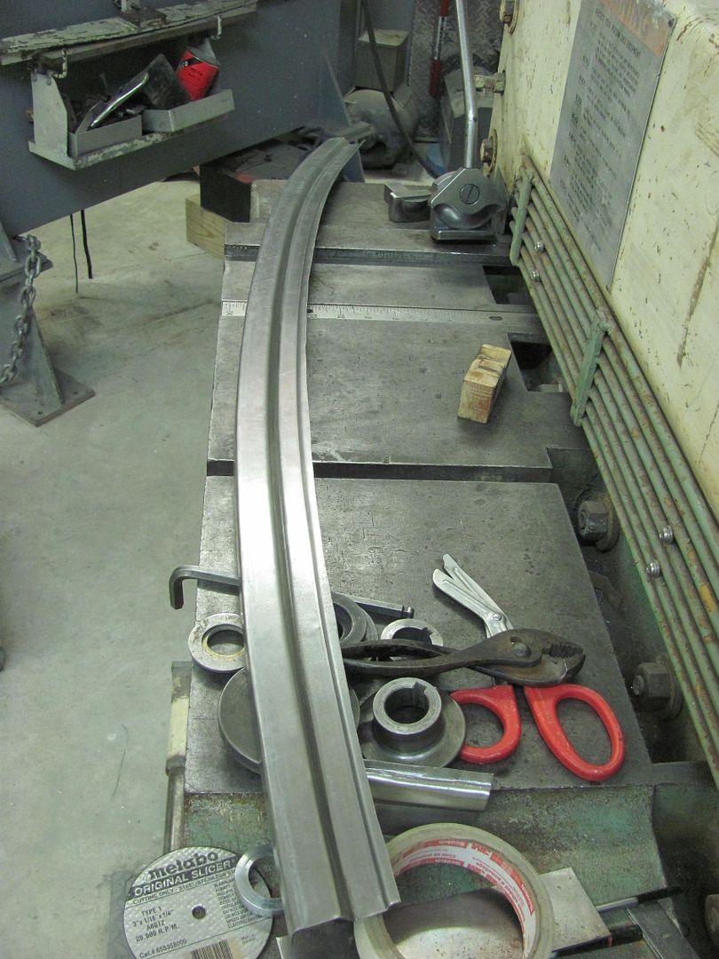
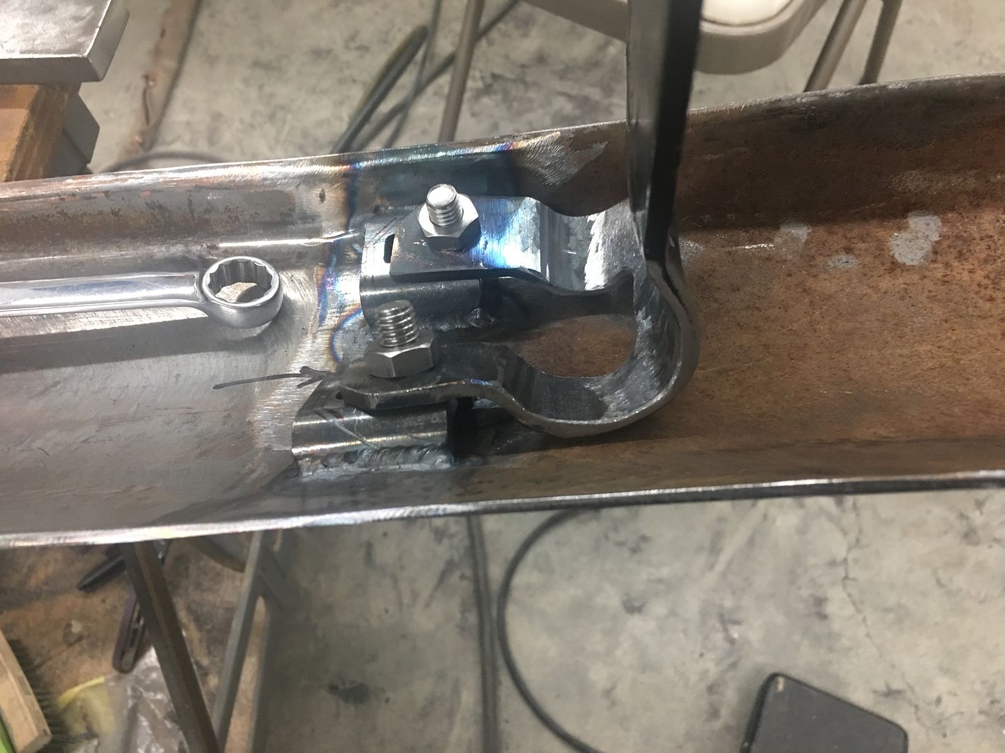
So to fix that we'll make up a new bottom die to form the ramp fold fully, then change back to the above die to form the step..

Picture%204500.jpg


Picture%204497.jpg


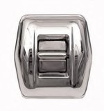
The down side to using phenolic is that it gives a bit where it doesn't make sharp creases well or short reverse folds either. The initial practice pieces wouldn't fold the step down flat, so a wrap of steel was added to the top die to better persuade the step flat...

Picture%204503.jpg


Picture%204504.jpg


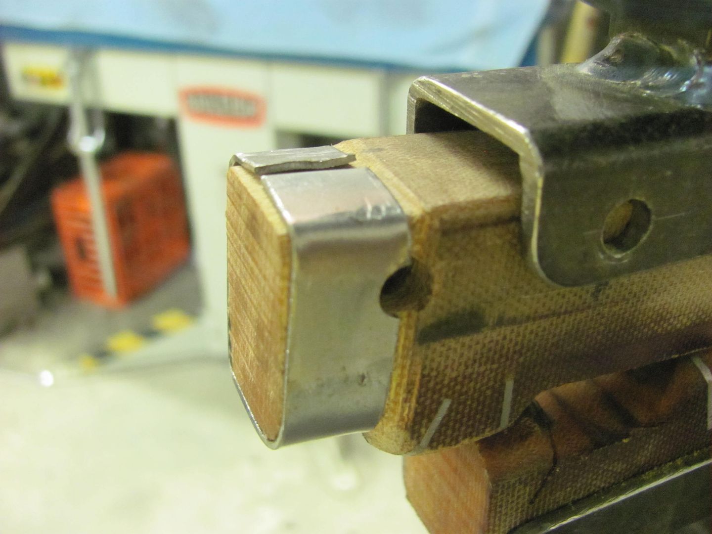
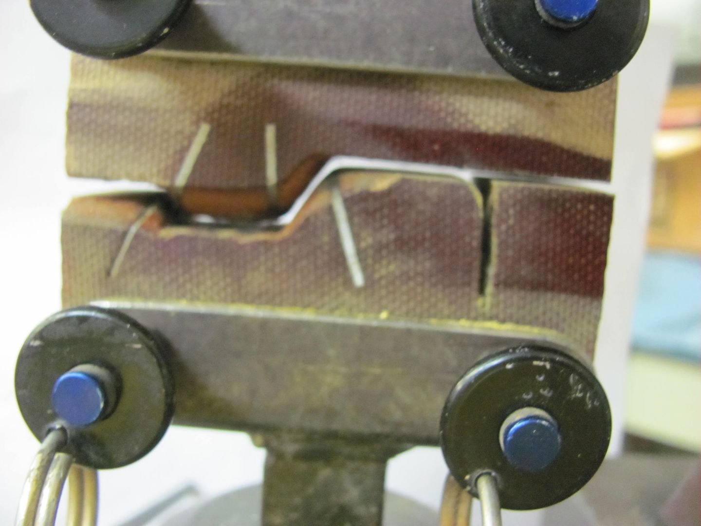
The upper die holder helps keep the wrapped steel in place.

Picture%204505.jpg


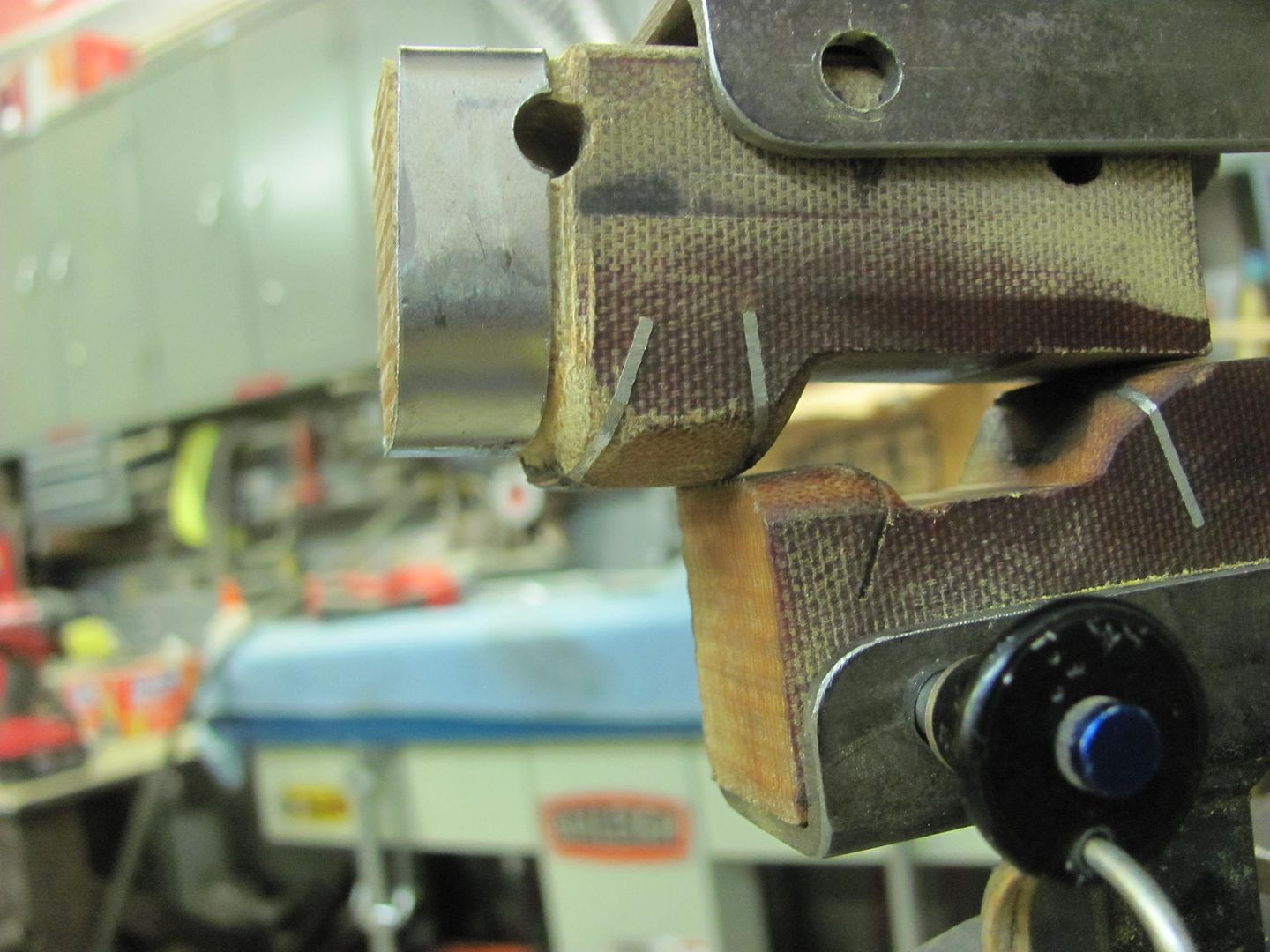
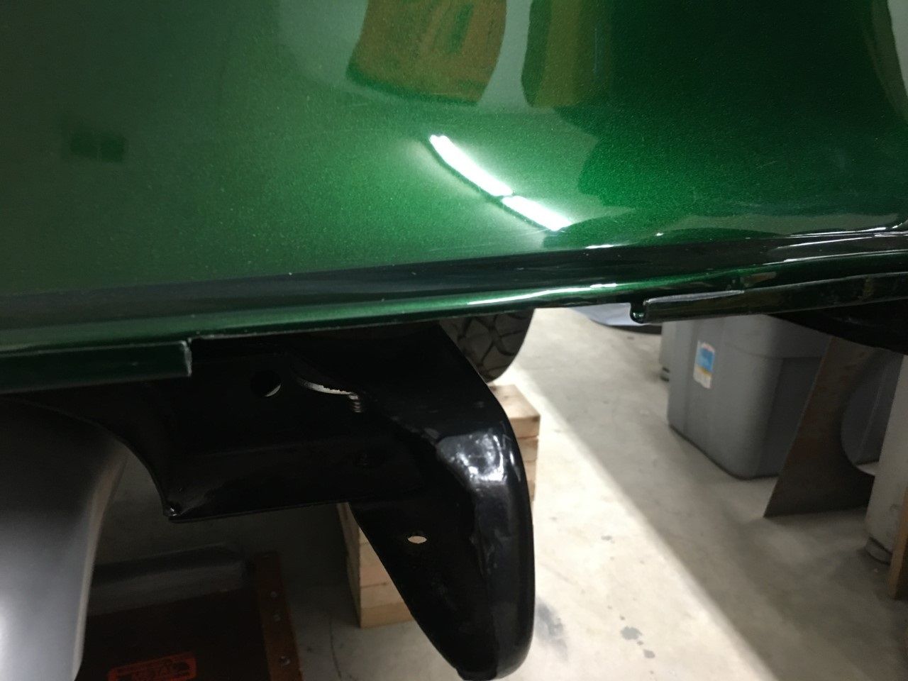
That did the trick, step is laying down nice and flat..

Picture%204498.jpg


Picture%204499.jpg


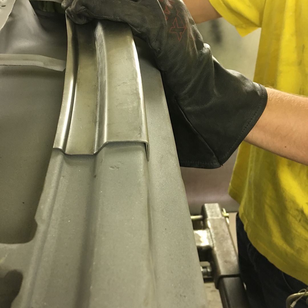
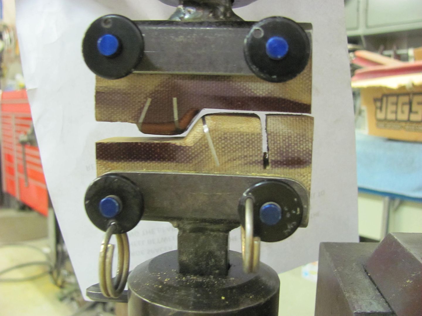
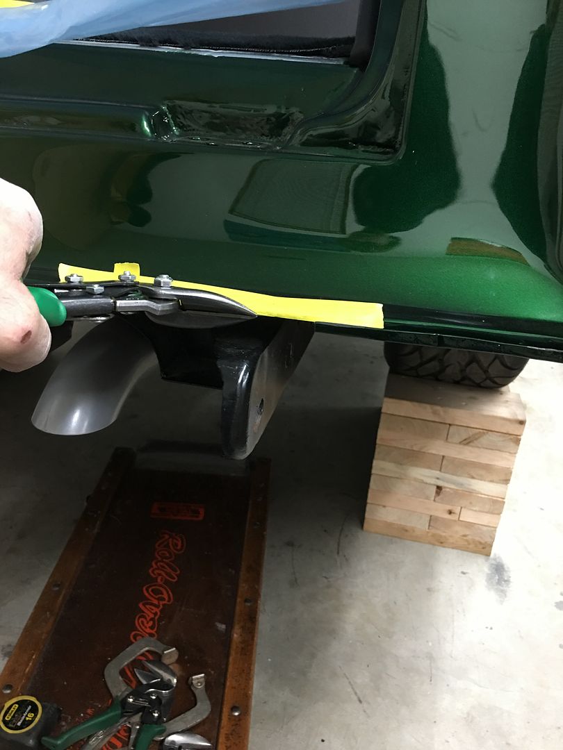
The front flange hangs over just a bit too much, some hammer action will bring it back in place. Real pleased with how well this turned out..

Picture%204506.jpg


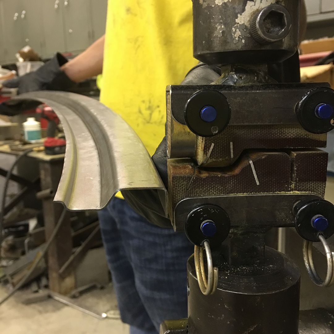
Some of the practice scraps..

Picture%204507.jpg


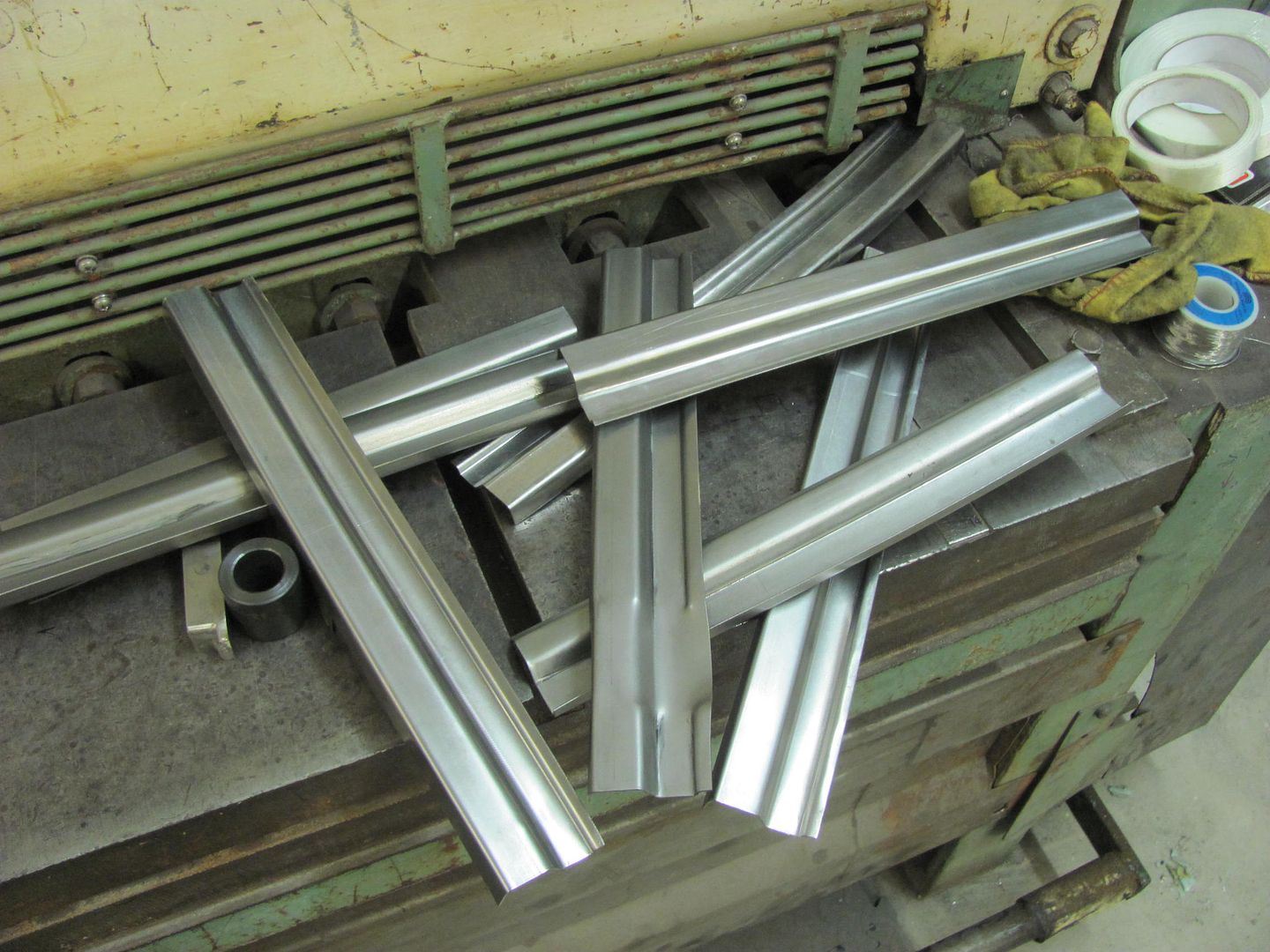
So whenever I see a scrap pile such as shown above, in my mind someone is learning. I try to show that scenario whenever I can to help instill in people that even though you may not get something "acceptable" the first time, use those challenges to fine tune your approach so you are in a constant mode of self-improvement. Thanks again for the feedback!
 
To avoid these ads, REGISTER NOW!
OP
M

MP&C

Well-known member
Joined
Oct 21, 2009
Messages
4,396
Location
Leonardtown, MD
So we had some tilt in windows we were cleaning up and found one with one of the "pivots" rusted off at the end. So another was pulled as a sample, got to be able to make one of these. They were a folded "pin" made of 16 gauge steel sheet, approx. .312 wide and two folded sides approx. .20 high. I attempted a die set for the Lennox, but that attempt failed miserably (picture later....) The magnetic brake has never worked well with anything having such a short fold, so that attempt saw the piece slipping, to no avail. So we are back to a press brake operation. I had some 1/2" wide dies, but the VEE relief was too wide for such a short flange. Since the press brake dies have two sides, why not cut another VEE on the bottom side?


IMG_9042.jpg


The overall width of the VEE needed to be less than 1/4 per initial estimates. I took the die section to Combs Prototype and Fabrication so Randy could cut the VEE for me, we settled on approximately .20 wide.


IMG_9041.jpg


Finished cut, fresh from Randy's HAAS machining center, and then I bent up a back gauge held on by magnets...


IMG_9050.jpg


Since Randy's VEE bit was a 90, springback effect gave us a slightly gapped opening of the flanges, so this prototype was snugged down in the bench vise.. Here's the side by side comparison...


IMG_9044.jpg


IMG_9045.jpg


While the machine was set up, we made multiples in case we ran into any other rust issues elsewhere. Next, for consistency in the side folds, the dies in the press brake were changed out to flat sides out, and set up the limit stop to provide the perfect 90* fold for the sides. To properly position the part, magnets were used to keep the bottom flat perpendicular to the die faces. Then all the parts were pressed to overcome the springback. Now all the parts will have 90* folds.


IMG_9051.jpg


Comparison....


IMG_9046.jpg


Holes pre-drilled for our self tapping screws….and a comparison to our mangled up mess from the attempt on the Lennox.


IMG_9048.jpg


So many years of working with worn out junk, you learn workarounds like this :lol:
 
Last edited:

mopar4don

Well-known member
Joined
Mar 9, 2013
Messages
103
Hi Robert,
Do you have a pic showing your piece in the vee die after bending it?
Sorry I am just not following you. I need a visual aid
 
OP
M

MP&C

Well-known member
Joined
Oct 21, 2009
Messages
4,396
Location
Leonardtown, MD
In another back up and punt moment, we found some interference with the new bumper brackets and the rear tailpan. In order to tuck things in nice and close, we need to trim a portion of the rear channel in the tail pan. Nothing a pair of tin snips and a file can't resolve. Pay no attention to that green paint. The bare edges will be touched up with SPI epoxy primer..


IMG_9028.JPG


IMG_9052.JPG


IMG_9053.jpg


Our final test fit on the back bumper before chroming:


On to our tail light hidden fuel fill...…


This thing had been giving us fits in intermittent operation, and it hasn't even been exposed to water yet. Looking at the wiring (why can't we keep the colors consistent through?)…..


IMG_9058.JPG


Well this isn't part of the problem... found a couple loose terminals..


IMG_9056.JPG


IMG_9060.JPG


So we decided to eliminate the original trailer connector and term board connections and replace with Weather Pack connectors. The relays will be mounted behind the rear seat for a closer proximity to the tail light, and the DPDT toggle switch will be replaced with a DPDT momentary rocker.


IMG_9057.JPG


IMG_9061.JPG


On a side note, a recent task for the day job involved some cherry trim boards that were pre-stained and we had difficulty finding a match using Minwax blend-fill pencils. The Number 3, 5, and 6 were all off....


IMG_9012.JPG


However, kneading the 3 and 5 together showed promise. But how to do that on a larger, less time consuming scale. I will say none of the wife's wax melting pots were harmed in this experiment, but the trim screw holes in stained trim were all but invisible when done. The pencils were unwrapped, cut up into 1" lengths, then melted and mixed together. In case someone else needs to do the same...


IMG_9013.JPG
 

JoelReeves

Member
Joined
May 16, 2017
Messages
10
You can usually find a crock pot for under $5 at a "Garage Sale".

Or stick an empty jelly jar in a pot of water on the stove.
 

BMW Rider

Well-known member
Joined
Apr 8, 2010
Messages
346
Location
Calgary, Alberta, Canada
How was thee cherry trim finished? Cherry is a photo reactive wood and will darken to its characteristic deeper reddish tone with time and exposure to sunlight. Even with stain and finish, it will likely change colour over time. Hopefully the wax does not end up lighter than the wood.
 
OP
M

MP&C

Well-known member
Joined
Oct 21, 2009
Messages
4,396
Location
Leonardtown, MD
How was thee cherry trim finished? Cherry is a photo reactive wood and will darken to its characteristic deeper reddish tone with time and exposure to sunlight. Even with stain and finish, it will likely change colour over time. Hopefully the wax does not end up lighter than the wood.


It was finished by a local cabinet shop that also made the furniture in the room. The trim was finished to match. I would add that these rooms do not get any sun exposure.


Joel, the one pictured was a $5 purchase from a thrift store, so sounds like we got the going rate.. :lol:
 
OP
M

MP&C

Well-known member
Joined
Oct 21, 2009
Messages
4,396
Location
Leonardtown, MD
So part of our fitment exercises with the bumpers has been to get them in a little closer to the body for more consistent gaps to the body. The rear bumper had it's challenges with needing to notch out the lower lip of the tailpan.


IMG_9052.JPG


IMG_9053.jpg


IMG_9028.JPG


IMG_9029.JPG


IMG_9030.JPG


The front would be no different. The front nose of the frame rails was hitting the rear side of the factory brackets and preventing us from locating the bumper for a good consistent gap..


IMG_9120.JPG


So some modification was in order so that the frame horn could fit in closer to the rear side of the bumper..


IMG_9121.JPG


We now have a much better fit..


IMG_9138.JPG


IMG_9140.JPG


IMG_9141.JPG


IMG_9142.JPG
 

J Persons

Well-known member
Joined
Jul 27, 2010
Messages
640
Location
Louisiana
This thing had been giving us fits in intermittent operation, and it hasn't even been exposed to water yet. Looking at the wiring (why can't we keep the colors consistent through?)…..


IMG_9058.JPG


Well this isn't part of the problem... found a couple loose terminals..


IMG_9056.JPG


IMG_9060.JPG


So we decided to eliminate the original trailer connector and term board connections and replace with Weather Pack connectors. The relays will be mounted behind the rear seat for a closer proximity to the tail light, and the DPDT toggle switch will be replaced with a DPDT momentary rocker.


IMG_9057.JPG


I used to use the Delco Weatherpacks, but discovered that they either lost or sold their patent and some of them available now are of questionable quality, and subject to breaking when closing the tabs. I switched to Deutsch Connectors, a bit more expensive but much better quality.
 
To avoid these ads, REGISTER NOW!
OP
M

MP&C

Well-known member
Joined
Oct 21, 2009
Messages
4,396
Location
Leonardtown, MD
Thanks for the heads up.. So far so good with the ones we have.....even have reopened some with no issue.. :fingerscrossed:
 
OP
M

MP&C

Well-known member
Joined
Oct 21, 2009
Messages
4,396
Location
Leonardtown, MD
So we've started on our wiring, what can go wrong? First item on the list is the interior lights, we had run the wires before the headliner went in. We had installed a second light just behind the rear seat and the plans were to gang it to the front light by putting two wires into a 12 gauge pin in the weatherpack connector. This should be a 5 minute job.

Only the weatherpack connector would not fit inside the void in the ceiling. Since we don't intend on using **** splices, we had tried installing two wires previously into the w-crimp lamp base contacts as shown:


IMG_8624.JPG


IMG_8626.JPG


This sample we did using the red Teflon insulation fit inside the brass "tubes" of the lamp base perfectly. But the insulation on AAW wiring is much thicker. Ahhh, the dominoes they do fall. So let's see what we can do to modify the brass tubes to better accept the wiring going in. Our local Ace hardware has a good selection of "model" tubing in aluminum and brass, so with fingers crossed, we picked up the 3/16 size.


IMG_9155.JPG


The ID measured out to .154, about .010 larger than what the lamp base came with. The outside diameter of the tube was turned down on the lathe to a size that would play nice inside the plastic housing and not bind on the spring.


IMG_9148.JPG


Some aluminum bar stock was drilled with a tight clearance hole for our new tube, and served as a fixture to swage one end for spring retention. Sorry, missed pictures of some of the details (fire the photographer). The opposite end was swaged after insertion into the housing..


IMG_9154.JPG


IMG_9153.JPG


With the tubes now sized for two wires, we got the front light installed. The rear light and its single wires should now be a breeze.


IMG_9156.JPG


IMG_9157.JPG
 

txvwnut

Well-known member
Joined
Jan 1, 2015
Messages
7,588
Location
Bedford, Texas
Seeing this reminds of when I was working on a friend of mines 56 Bel-air. I was doing some wiring repair from additions from years past and doing this in his garage. He had left to run an errand and when he returned he exclaims, you got the dome light working. He had owned this car since 63 and dome the light never worked. Seems someone on the assembly line ran a screw for the sill plate through the wiring harness and got the dome light wire.
 

xtremek

Well-known member
Joined
Apr 13, 2012
Messages
11,603
Location
St. Johns, Mi
Nice job on the wiring. You're lucky the hardware had that in stock, doesn't seem like a normal carry item for a hardware store.
 
OP
M

MP&C

Well-known member
Joined
Oct 21, 2009
Messages
4,396
Location
Leonardtown, MD
Seeing this reminds of when I was working on a friend of mines 56 Bel-air. I was doing some wiring repair from additions from years past and doing this in his garage. He had left to run an errand and when he returned he exclaims, you got the dome light working. He had owned this car since 63 and dome the light never worked. Seems someone on the assembly line ran a screw for the sill plate through the wiring harness and got the dome light wire.

We still have yet to get to that stage.. I guess a sleeve around the screw hole would be helpful... Thanks for the insight!

Nice job on the wiring. You're lucky the hardware had that in stock, doesn't seem like a normal carry item for a hardware store.

The local Ace just got bought out and is in a major re-organization. They were out of one size, so yes lucky they had the right one..

That’s definitely a great work around. I would have lost my mind !!!

Thanks Dave!
 
OP
M

MP&C

Well-known member
Joined
Oct 21, 2009
Messages
4,396
Location
Leonardtown, MD
Progress from yesterday, while Jared was blocking out some of the window garnish moldings, I worked on the door panel stainless trim to ready them for stud welding. Mike had used the trim repair tool to remove the dings, which were then filed smooth.


IMG_8938.JPG


The last 65 years had left their mark; we had numerous scratches needing removal as well. We started with 320 grit on the fine pattern palm sander, and progressed our way up to 8000 grit trizact..


IMG_9202.JPG


IMG_9203.JPG


IMG_9204.JPG


IMG_9205.JPG


IMG_9206.JPG


This is the final using the 8000 grit, and we'll start the buffing process once the stud welding had been completed..


With the stainless prepped, we turned attention to the window garnishes. They were sprayed with three coats of SPI epoxy.


IMG_9211.JPG


IMG_9215.JPG


Today we went to A&A Metalworks in Ridge MD to get the studs welded in place. This sample shows the studs, where three have been folded over to a 90. This is how the factory held them onto the door panels as well. Note the back side shows no heat pattern with the Capacitive Discharge welder.


IMG_9217.JPG


IMG_9218.JPG


Welding the studs onto the stainless trim...


Our results...


A test to check the heat the welder introduces into the panel..


This shows these welders make a good choice to use where cases of heat sensitivity may be an issue.
 
OP
M

MP&C

Well-known member
Joined
Oct 21, 2009
Messages
4,396
Location
Leonardtown, MD
We had tried this same machine using pulling pins for a stud welder (bodywork type) but the pins/nails had too much bulk at the weld end, and the weld did not perform properly with consistent results. The CD welder studs/nails have a pin point on the end that touches the panel for a more focused weld dealio..
 
Last edited:
OP
M

MP&C

Well-known member
Joined
Oct 21, 2009
Messages
4,396
Location
Leonardtown, MD
Happy Easter everyone!


Our wagon progress from this weekend, we finished up the interior lights. Here wiring up the rear light. The included pigtails were discarded to eliminate a **** splice, and our newly installed wiring made use of new lamp base contacts (W crimp) from Repair Connector.


IMG_9257.JPG


IMG_9259.JPG


The lens used in light fixtures like these are typically plagued over the years by overheating and then cracking, so we opted for a 1004 LED replacement. Should keep things cooler for longer lens life, and brighter!!


IMG_9264.JPG


IMG_9260.JPG


Onto more electrical issues, the "hidden fuel door" we had purchased was so intermittent in operation that when we had dropped it off at Absolute Rod & Custom Paint to test fit to the car when they were fine tuning the bodywork, we were second guessing whether we should use it at all.


All the harnesses came into a terminal board with wires going to the relays on the opposite side. Some of the terminals had as many as three wires in them, and Mike Flores found about 6 loose wires. Splices didn’t carry the same wire color through, making trouble shooting a bit of a challenge. The toggle switch (which should have been momentary contact but was not) had some home-made fork terminals. This thing was looking more sketchy with everything we looked at next. For a store-bought product intended for an automotive environment, they should find someone more competent in wiring.


IMG_9056.JPG


IMG_9058.JPG


To get rid of the terminal board, we opted for weather pack connectors, one to each of the end terminations (switch, fuel door, power source). We eliminated the triple wires to single terminal by jumpering, making use of two wires in a single pin, and jumpered as required.


IMG_9265.JPG


IMG_9266.JPG


IMG_9267.JPG


Our new wires going into the relay connectors made use of new Packard 56 style female spade terminals from www.repairconnector.com (more W-crimp) These were also jumpered two wires to a pin where needed.


IMG_9271.JPG


IMG_9272.JPG


The toggle switch was replaced by an automotive grade MOMENTARY rocker switch from McMaster. Works flawlessly.


IMG_9275.JPG


Not pretty, but much improved. The relays will be located behind the rear seat on the sub box, conveniently between all our end points. Just like our speaker grilles, black plastic really doesn't belong in plain view in a 55 Chevy. So our more highly functional rocker switch will be hidden inside the glove box..
 
OP
M

MP&C

Well-known member
Joined
Oct 21, 2009
Messages
4,396
Location
Leonardtown, MD
Has to be a DPDT. Might be one out there in a push button, but I couldn't find it.. Got one we ordered last month that doesn't work.. :lol:
 

shortykorte

Well-known member
Joined
Sep 1, 2014
Messages
8,034
Location
Tallahassee, Fl
I need the name of that company so I can hire them to wire my house. Not!

Your fix looks really nice. Maybe with Raspberry Pi or Aquino you could get gas door to operate via cellphone.


Sent from my iPhone using Garage Journal
 

jimkinney

Well-known member
Joined
Jan 3, 2009
Messages
298
Location
Florida's Space Coast
Has to be a DPDT. Might be one out there in a push button, but I couldn't find it.. Got one we ordered last month that doesn't work.. :lol:

May not be worth the complexity or extra parts, but a push button switch could power a double pole relay in place of the switch. It would require two switches and relays.

Nice work cleaning up the wiring mess. I used to build wire harnesses and that kind of work offends me.
 

Bob Heine

ALLIANCE MEMBER
Joined
Oct 24, 2009
Messages
10,703
Location
Boca Raton, Florida
Robert, I plan to use a pushbutton switch to open and close electric cutouts on the Corvette so I did a search on that. It's a DPDT switch and it's metal or at least looks like metal. Might be easy to conceal inside by the tailgate.
attachment.php


With the part number you might be able to find one locally. TE Connectivity makes these in a couple of sizes. Here's a link to the 19mm size:

https://www.te.com/usa-en/product-2213763-7.html
 

Attachments

  • Pushbutton Switch for Cutouts.jpg
    Pushbutton Switch for Cutouts.jpg
    39 KB · Views: 995

Stuart in MN

Well-known member
Joined
Sep 8, 2005
Messages
22,986
Location
Minneapolis
The toggle switch was replaced by an automotive grade MOMENTARY rocker switch from McMaster. Works flawlessly.

Not pretty, but much improved. The relays will be located behind the rear seat on the sub box, conveniently between all our end points. Just like our speaker grilles, black plastic really doesn't belong in plain view in a 55 Chevy. So our more highly functional rocker switch will be hidden inside the glove box..

How about using a reproduction power window switch? This is a repro 1955-1957 Chevy switch, but there are other styles available.
 

Attachments

  • switch.jpg
    switch.jpg
    20.4 KB · Views: 27

GrahamZ3

New member
Joined
Apr 27, 2021
Messages
1
Location
AZ
I just registered to tell you what an inspiration this thread has been to me, a novice welder with aspirations to be half as decent a metalworker as MP&C. It is truly an art form at the level he is at and whenever I am feeling a little unmotivated, I just read a bit of this thread and find the motivation to get cracking on whatever job I am stalled on... I'm only way back on page 20 (of 190, on my forum settings) as well :)
Very, very cool :beer:
 

iajonesy

Well-known member
Joined
Feb 8, 2009
Messages
2,467
Location
Iowa
Robert, do you have any idea what Dave Kindig uses for his exhaust cut outs and on the 55 Nomad tail light fuel fill? It appears to be a DPDT in one switch much like the one Bob Heine posted.

Mike
 
OP
M

MP&C

Well-known member
Joined
Oct 21, 2009
Messages
4,396
Location
Leonardtown, MD
Duh. I blame not enough caffeine. :rolleyes: 
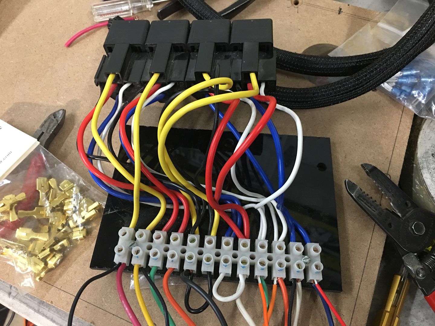
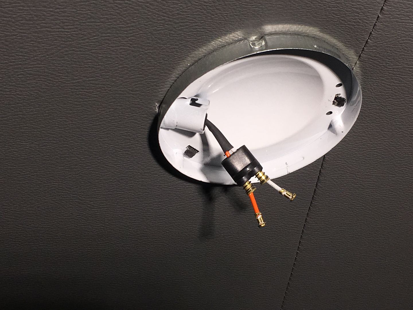
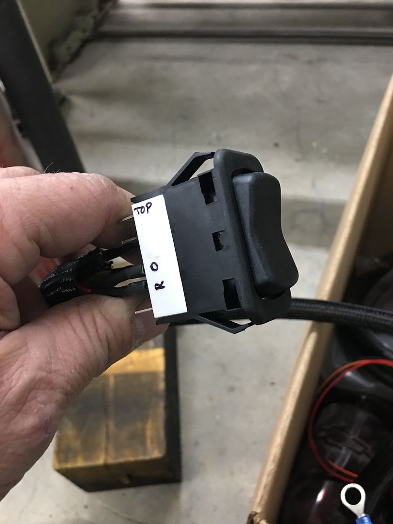
What about a reversing relay and the cigarette pushbutton

I need the name of that company so I can hire them to wire my house. Not!

Your fix looks really nice. Maybe with Raspberry Pi or Aquino you could get gas door to operate via cellphone.


Sent from my iPhone using Garage Journal

May not be worth the complexity or extra parts, but a push button switch could power a double pole relay in place of the switch. It would require two switches and relays.

Nice work cleaning up the wiring mess. I used to build wire harnesses and that kind of work offends me.

Robert, I plan to use a pushbutton switch to open and close electric cutouts on the Corvette so I did a search on that. It's a DPDT switch and it's metal or at least looks like metal. Might be easy to conceal inside by the tailgate.
attachment.php


With the part number you might be able to find one locally. TE Connectivity makes these in a couple of sizes. Here's a link to the 19mm size:

https://www.te.com/usa-en/product-2213763-7.html

How about using a reproduction power window switch? This is a repro 1955-1957 Chevy switch, but there are other styles available.


You guys are killing me! :D Here I'm trying to get done this year... :willy_nil


I just registered to tell you what an inspiration this thread has been to me, a novice welder with aspirations to be half as decent a metalworker as MP&C. It is truly an art form at the level he is at and whenever I am feeling a little unmotivated, I just read a bit of this thread and find the motivation to get cracking on whatever job I am stalled on... I'm only way back on page 20 (of 190, on my forum settings) as well :)
Very, very cool :beer:


Graham, welcome to GJ! Look around, stay awhile..


Robert, do you have any idea what Dave Kindig uses for his exhaust cut outs and on the 55 Nomad tail light fuel fill? It appears to be a DPDT in one switch much like the one Bob Heine posted.

Mike


Mike, I do not know what he's using..
 
To avoid these ads, REGISTER NOW!
Top Bottom