To avoid these ads, REGISTER NOW!

MP&C Shop Projects

To avoid these ads, REGISTER NOW!

TimeWarpF100

Well-known member
Joined
Aug 21, 2010
Messages
6,784
Location
not here
More progress on the (second) fan shroud, but I had a request to show the process in greater detail.. So we'll start with the beginning.

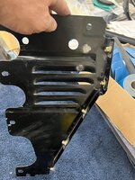
First was the layout of the bend line, and then the cut line was located about 3" inside of that. (I'm using some of the pictures from our first attempt as our shop photographer missed some the second time around)


IMG_0162.jpg


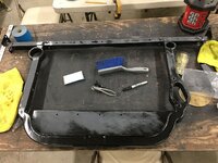
The initial stretch was done using a blocking hammer on the top (flat area) of the stump, primarily at the inside edge as that needed the most stretch.


IMG_0441.jpg


On our first attempt we had a hammer form that was used to "set" the bend line with a crowned body hammer as we added the first bit of stretch.


IMG_0451.jpg


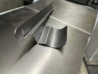
This seemed a bit cumbersome, and the second version I used a bent portion of round stock that was in the scrap pile, added a piece of pipe for a handle, and the band saw added a slice for a new tipping tool. The bend in the tipping tool gave it a built in fulcrum. Normally a tipping operation tries to pull the adjacent material along as the bend forms. In this case we set the panel on a table and used the bend (fulcrum) of the tipping tool against the table to pull the stretched area downward. This allows us to push down on the handle to elevate the panel off the table, and to push downward on the flat panel outside the bend line with the palm of your hand. This does a good job of placing the bend where needed without pulling adjacent metal along for the ride. Even though the pictures show the stretched area upward, the panel was placed with this area downward when using the tipping tool..


IMG_0341.jpg


IMG_0342.jpg


IMG_0343.jpg


This worked much better at setting the bend line than the hammer form, and it was surprisingly accurate.


Much of the stretch was done using linear stretch dies on the power hammer, but we also reverted back to the blocking hammer and stump to better focus the stretch locations.


IMG_0442.jpg


The other issue to overcome with both hammer operations was that they didn't play nice with keeping the shroud in a flat vertical. So the next tool used was a 90 durometer pad of polyurethane and the Model A leaf spring hammer. The hammer face was too short to match the shroud height (approx 3") so three passes were done to cover the entire height and with each pass the hammer hits were about 1/8" or so apart.


IMG_0443.jpg


IMG_0444.jpg


IMG_0445.jpg


IMG_0446.jpg


The bulk of the stretch was done on the power hammer, and the front of the lower die holder is missing quite a bit of paint from this job...


IMG_0447.jpg


The completed bend, we started with .044 thickness (18 gauge) and it was thinned to .029 thick, or lost about 1/3 thickness to turn the 90...


IMG_0437.jpg


IMG_0438.jpg


IMG_0439.jpg


IMG_0440.jpg


Thanks for all the good update stuff! Nice to see engine fire up!
 
OP
M

MP&C

Well-known member
Joined
Oct 21, 2009
Messages
4,396
Location
Leonardtown, MD
Thanks guys!!

I want those cabinets :oops:

Just one of them would have been a find.. When I saw the pair advertised, I couldn't pass them up..


More progress... using our rare earth magnets on the end of the bead roller die to correct the "back spacing", the fan shroud has the center bead added...


IMG_0250.jpg


Next, adding the outer joggle for the wire. Our last mis-step at this stage was expecting a folded flange to perform as it did on a flat piece of metal.. But as a full circle with 1/2" of flange, it tends to resist any change in diameter, so our efforts to add the joggle (stretch outward) were met with catastrophic failure in the way of a split. This next attempt will leave that edge straight out instead of flanged, such that it will be more apt to move/stretch as we need it to.. Additionally, our dies will have a backstop built in and include two bead forming details. One will follow the center bead already installed, and with the back stop as part of the die, should correct any wiggle our bead roller may have added. Having both bead details added to the dies will also help to maintain correct spacing throughout. As these beading dies tend to pull material from either side, having multiple beads makes it more of a challenge to pull sufficient material for both and have enough for the bead height.. Adding one prior using the bead roller means we will only be "pulling" material for the one, for better results.


IMG_0497.jpg


Our test sample shows the wrap for the wire straighter to the side, for less resistance to adding the offset.


IMG_0496a.jpg


Shroud is then trimmed to size and run through the dies on the Lennox..


IMG_0510.jpg


IMG_0513.jpg


IMG_0514.jpg


IMG_0515.jpg


This did give us a slight potato chip shape of the panel, so the offset was stretched in the Erco..


IMG_0517.jpg


IMG_0518.jpg


Our tubing straightener is used to make our 3/16 wire more concentric for an easier install..


IMG_0509.jpg


Then the wire was test fit...


IMG_0519.jpg


IMG_0520.jpg


Mike got our interior assembly and wiring started, the rear tail light / fuel door actuator was installed, the sub box and amp installed, and our relays for the fuel door mounted adjacent to the amp, all tucked away behind the rear seat.


IMG_0492.jpg


IMG_0494.jpg


IMG_0523.jpg


IMG_0525.jpg
 

WoodsTruck

Well-known member
Joined
Jan 12, 2013
Messages
1,019
I think there is one major thing I have learned reading through this thread specifically. The end result is often the result of the time spent building the special tool needed for the job. I'm usually in such a hurry with getting to the end zone that I don't take the time to build the right jig or fitting to make the end result I'm after. Now that I am more likely to slow down and enjoy building the tools to finish the job I'm often more proud of the tool than the original project.

Excellent work and I really appreciate your photos and description on how you were able to accomplish the tasks.
 

stinkity stoink

Well-known member
Joined
Apr 8, 2007
Messages
729
Location
New Jersey
Even the details on the fan shroud are incredible. I’m pretty certain nobody will realize the time and effort put into that by just looking. I would bet they think you just bought it. Great work and really appreciate the documentation!!
 
OP
M

MP&C

Well-known member
Joined
Oct 21, 2009
Messages
4,396
Location
Leonardtown, MD
I think there is one major thing I have learned reading through this thread specifically. The end result is often the result of the time spent building the special tool needed for the job. I'm usually in such a hurry with getting to the end zone that I don't take the time to build the right jig or fitting to make the end result I'm after. Now that I am more likely to slow down and enjoy building the tools to finish the job I'm often more proud of the tool than the original project.

Excellent work and I really appreciate your photos and description on how you were able to accomplish the tasks.


Thanks, I think a lot of it stems from us working nights and weekends, you find out what you ordered doesn't fit or don't feel like waiting on something if you did order it or it's not available, so we've done quite a bit of fabrication because of it... Do what it takes..


Even the details on the fan shroud are incredible. I’m pretty certain nobody will realize the time and effort put into that by just looking. I would bet they think you just bought it. Great work and really appreciate the documentation!!


Two piece and it would have been done by now, but sometimes you do something just to see if you can, and what it would take to do so. I think you learn so much more by not taking the easy road.. Like why on earth did I do that? :ROFLMAO: Thanks Dave!


Wow, just wow.

Your bead roller looks like it needs a new motor. That one takes a lot of breaks.


Jim, there may be a slight miss....
 
OP
M

MP&C

Well-known member
Joined
Oct 21, 2009
Messages
4,396
Location
Leonardtown, MD
More progress on the fan shroud... Wire edging!! In order to stave off any rust issue as long as we can, I normally treat the wire channel to epoxy primer from the inside-out. So we used a scotchbrite pad and some Ivory liquid in warm water to remove any last remnants of the WD40 used for the last shaping effort on the Lennox.


IMG_0539.jpg


IMG_0540.jpg


Our wire had been test fitted, sized, and tig welded together to form a continuous ring. This adds tremendous strength to the edge and helps to maintain a concentric circle. The wire was then cleaned as well. SPI epoxy was hand applied (acid brush) to the channel, the wire ring pressed in place (it was that tight) and then any bare spots on the ring epoxied as well..


IMG_0541.jpg


IMG_0557.jpg


IMG_0558.jpg


IMG_0559.jpg


The vise grips hold the wire snug to the bottom of the channel until the edge of the flange can be staked in place. Wire edging process, done using our cone anvil, various hammers, and a 90 durometer polyurethane pad for the final closure of the wrap..


At the point we were hammering, the epoxy had set up approx 10-15 minutes, so it was not dry yet, but not running either. We'll let the epoxy set a couple days and get additional coats in the slight gap at the edge of the wrap in order to seal things well for rust prevention.


IMG_0567.jpg


IMG_0572.jpg


IMG_0573.jpg


And our inside dimension worked out to what we were looking for, 18-1/8 diameter for our 17-1/4 fan blade.


IMG_0571.jpg


We also got another delivery, some 4" louver dies from Mittler Bros Machine and Tool for another job coming up. Will have to sneak it in here on some wagon parts as well.


IMG_0529.jpg
 
OP
M

MP&C

Well-known member
Joined
Oct 21, 2009
Messages
4,396
Location
Leonardtown, MD
With all the fabrication going on, the car is still draped with shark grip to protect the paint.. as seen here...


IMG_0514.jpg
 

BORING HOP YARD

Well-known member
Joined
Jan 13, 2007
Messages
1,098
Location
Boring Oregon
Question from the peanut gallery.
What is "draped with shark grip"
I searched, but could only find paint additives for traction.
I have projects in my shop that are in final paint and have fabrication going on as well.
Just want to make sure I don't miss a better way to protect.
Thanks Robert!
 
OP
M

MP&C

Well-known member
Joined
Oct 21, 2009
Messages
4,396
Location
Leonardtown, MD
Looks like I morphed the name a little. Should have said Shark Skin, but there are variants of it by 3M and other manufacturers. It’s a light plastic used to drape off a car in painting environment and has a slight amount of static to help it stay where you put it. Comes in either 12’ or 16’ wide rolls by about 400’.
 
OP
M

MP&C

Well-known member
Joined
Oct 21, 2009
Messages
4,396
Location
Leonardtown, MD
Looking at the fan shroud, the top and bottom will be stepped where it bolts behind the rear edge of the core support.


IMG_0579.jpg


The sides will get a radius bend to bolt to the inside vertical of the core support. This still leave quite a bit of flat metal that just doesn't have much style to it. So let's try some embossing on the side panels.. To better keep things a consistent pattern from left to right, we made a pattern using MDF board..


IMG_0609.jpg


IMG_0610.jpg


An offset die set is made in the Southbend lathe, the rounded sides will allow it to better travel along the pattern cutout.


IMG_0584.jpg


IMG_0585.jpg


We did a test run on our split original shroud, I had intended for the pattern to be inset when looking at the back.. Someone had the pattern clamped on the wrong side, and it was pressed outward instead.. Hindsight, when looking in the engine compartment from the side, the inset version would be more difficult to see the embossing, and this next "mistake" would be easier to see.


IMG_0634.jpg


IMG_0637.jpg


Sometimes things happen for a reason. So guess what we're going with.... The pattern did not have enough real estate to make a wide sweeping turn in the corners, so when using the dies we'll stop short of the corners and will coin them afterward by hand. Time lapse:


We did have one slip-up, should be an easy fix...


IMG_0670.jpg


Looks a bit less blah now....


IMG_0673.jpg
 
To avoid these ads, REGISTER NOW!

SM Racing

Well-known member
Joined
May 3, 2006
Messages
856
Location
Huntsville, AL
Saw this Shroud in person at the Redneck Roundup and it is an impressive piece of work. Robert, you have some impressive skills. Thanks for the tips on making the piece for the Mercedes spare tire well patches.

Brett
 
OP
M

MP&C

Well-known member
Joined
Oct 21, 2009
Messages
4,396
Location
Leonardtown, MD
Sorry for the hiatus, more travel for the day job.. hanging more TV's...


Back on the wagon, sometimes I get ahead of myself. The core support has rounded corners at the bottom....


IMG_6936.jpg


Our embossing did not....


IMG_0676.jpg


So the lower embossing was flattened, and marked for the new..


IMG_1094.jpg


IMG_1098.jpg


Next on the list, our upper radiator hose is a bit long and needed some support to keep it out of the fan. It's actually a lower hose for a Ford Explorer, but is a perfect fit for our cross flow radiator. So some 16 gauge cold rolled steel is used to fabricate a support bracket..


IMG_1173.jpg


IMG_1174.jpg


IMG_1176.jpg


IMG_1177.jpg


IMG_1178.jpg


IMG_1179.jpg


Next, we had moved the battery from the OEM location on the firewall to the dealer installed Air Conditioning location behind the core support. This has the battery in close proximity to the passenger side header, so we punched some louvers on the core supports side baffle to allow for air flow.


IMG_1196.jpg


IMG_1197.jpg


IMG_1202.jpg


IMG_1203.jpg


Attachments

  • IMG_1178.jpg
    IMG_1178.jpg
    193.2 KB · Views: 12
  • IMG_1179.jpg
    IMG_1179.jpg
    173.8 KB · Views: 10
  • IMG_1196.jpg
    IMG_1196.jpg
    230 KB · Views: 10
  • IMG_1197.jpg
    IMG_1197.jpg
    222.6 KB · Views: 9
  • IMG_1202.jpg
    IMG_1202.jpg
    350.3 KB · Views: 8
  • IMG_1203.jpg
    IMG_1203.jpg
    186.3 KB · Views: 8
  • IMG_1177.jpg
    IMG_1177.jpg
    204.3 KB · Views: 6
  • IMG_1176.jpg
    IMG_1176.jpg
    173.7 KB · Views: 6
  • IMG_6936.jpg
    IMG_6936.jpg
    238.7 KB · Views: 9
  • IMG_0676.jpg
    IMG_0676.jpg
    248 KB · Views: 7
  • IMG_1094.jpg
    IMG_1094.jpg
    133.1 KB · Views: 9
  • IMG_1098.jpg
    IMG_1098.jpg
    213.5 KB · Views: 8
  • IMG_1173.jpg
    IMG_1173.jpg
    492.3 KB · Views: 8
  • IMG_1174.jpg
    IMG_1174.jpg
    509.5 KB · Views: 15
Last edited:

xtremek

Well-known member
Joined
Apr 13, 2012
Messages
11,603
Location
St. Johns, Mi
No need to apologize, just glad you're safe and healthy. Also glad you posted about your miscalculation. Nice recovery. Always love seeing your work. It opens my mind on how to approach things.
 
OP
M

MP&C

Well-known member
Joined
Oct 21, 2009
Messages
4,396
Location
Leonardtown, MD
Ever since I got rid of my radial arm drill press years ago to make room for a band saw, I’ve been searching for the more compact replacement. Yesterday was that day. Small enough to hide in a corner, yet big enough to do the job. Nice and quiet too. Got to love quality tools/machinery


3191545A-0B1A-49F4-A660-870D960AF3E6.jpeg
 

PugetDude

ALLIANCE MEMBER
Joined
Mar 13, 2013
Messages
22,263
Location
Superstition Mountains, AZ
Ever since I got rid of my radial arm drill press years ago to make room for a band saw, I’ve been searching for the more compact replacement. Yesterday was that day. Small enough to hide in a corner, yet big enough to do the job. Nice and quiet too. Got to love quality tools/machinery


3191545A-0B1A-49F4-A660-870D960AF3E6.jpeg
Nice find, Robert! That’s a pretty pristine example. Hard to find one without “The arc of shame”
 
OP
M

MP&C

Well-known member
Joined
Oct 21, 2009
Messages
4,396
Location
Leonardtown, MD
Wagon progress! So Jared has been tackling the fun task of prepping interior trim pieces, getting them ready for another round of epoxy..


IMG_1476.jpg


IMG_1479.jpg


Another modification we're undertaking, the air cleaner, when mocked up on the engine, showed a tight proximity to the back of the AC compressor. Looking at the clearance we had to the firewall, moving backward 1" will give us much needed breathing room for the AC lines. So out with the old ....


IMG_1564.jpg


And to move rearward, the mounting hole is moved forward one inch..


IMG_1568.jpg


IMG_1569.jpg


IMG_1570.jpg


IMG_1572.jpg


Next in store is a new bottom for the air cleaner..


IMG_1575.jpg


IMG_1580.jpg


A hammerform is used to give us a folded lip out the bottom


IMG_1582.jpg


IMG_1585.jpg


IMG_1588.jpg


IMG_1595.jpg
 

tarmy

Well-known member
Joined
May 28, 2014
Messages
4,647
Location
Nor Cal
Teach me something….what is the first step on that hammer form process for initiating the turning up of that inside lip. I cannot tell from the vids(or missed it). in other words…do you just pound that bend into it…

thanks…great thread as well…been following for quite a while.
 
OP
M

MP&C

Well-known member
Joined
Oct 21, 2009
Messages
4,396
Location
Leonardtown, MD
At this point we need to hem the flange so the bottom isn't quite so sharp..


IMG_1595.jpg


A 1/2 x 1/2 aluminum angle is used as a height gauge so we can use the roloc sander to get our flange to a consistent height. This will allow us to use a tipping die in the bead roller to fold the hem..


IMG_1596.jpg


IMG_1599.jpg


IMG_1600.jpg


IMG_1607.jpg


IMG_1609.jpg


Then the part is re-installed in the hammer form to hammer the hem flat..


IMG_1610.jpg


IMG_1615.jpg
 
OP
M

MP&C

Well-known member
Joined
Oct 21, 2009
Messages
4,396
Location
Leonardtown, MD
Teach me something….what is the first step on that hammer form process for initiating the turning up of that inside lip. I cannot tell from the vids(or missed it). in other words…do you just pound that bend into it…

thanks…great thread as well…been following for quite a while.


Thanks for the question!! So we are trying to tip the flat over to a perpendicular (90*) so the first concern is that a flat body hammer has sharp edges and will leave excessive marks in the metal. So you want a radius faced hammer but not one so round it puts in dents.. So the hammer shown in the first video is a small blocking hammer which did a good job. I would add, this process is done incrementally. Start hitting the innermost part as it will need the most stretching, and then continue to reposition with each successive round in an attempt to keep what you're hammering over "flat". The more distorted you make it, the more difficult the task of getting things smooth in the end, so finesse normally wins over heft. As with anything metalshaping, our efforts shouldn't add extra work to clean up what we just did. IE: refine the process as needed.
 

tarmy

Well-known member
Joined
May 28, 2014
Messages
4,647
Location
Nor Cal
Thanks for the question!! So we are trying to tip the flat over to a perpendicular (90*) so the first concern is that a flat body hammer has sharp edges and will leave excessive marks in the metal. So you want a radius faced hammer but not one so round it puts in dents.. So the hammer shown in the first video is a small blocking hammer which did a good job. I would add, this process is done incrementally. Start hitting the innermost part as it will need the most stretching, and then continue to reposition with each successive round in an attempt to keep what you're hammering over "flat". The more distorted you make it, the more difficult the task of getting things smooth in the end, so finesse normally wins over heft. As with anything metalshaping, our efforts shouldn't add extra work to clean up what we just did. IE: refine the process as needed.
Thank you…as with most things…patience is a virtue…

now, I need a new project and, of course, new tools…
 
To avoid these ads, REGISTER NOW!
Top Bottom