To avoid these ads, REGISTER NOW!

Multi-Wire Branch Circuit - Common Neutral

Dyno Dan

Well-known member
Joined
Jan 31, 2012
Messages
121
Location
Southwest Montana
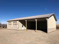
I started wiring my pole barn and have a few questions. **In the interest of disclosure, electrical work is not my thing. I’ve done some typical home owner stuff, ie replaced outlets, switches,etc etc, so I’m a little green in regards to experience. That being said I hired an electrician to run a 100 amp power service to my new building from an existing 200 amp panel. Since then I haven’t had much luck getting anyone back out here to run circuits for me.....so I’m going it alone”

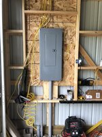
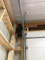
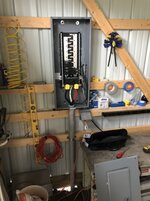
Picture of the panel:
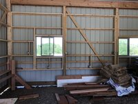
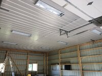
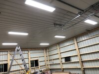
f264a8122179090d4a13d78f3a54c608.jpg

General layout:

4eace32f0ddb8567079040007d750dc6.jpg

My father-in-law talked me into running 12/3 (3 conductors and a ground) to have flexibility to run another circuit. I did so and my Intent is to have a multi wire branch circuit.....at least that’s what I think they call it :). The first circuit will have six outlets on it (black wire) over on the open side of the shop on back and side wall, while the other circuit I intend to have switched power for the lights (on red wire) over on the same side / open side of the shop. In this configuration I would have to share the neutral. I have a junction box to breakout the 2 circuits.

That all seems straightforward but here’s where I need some help. What’s the best way to run a switch for the light circuit? I could double back from my junction box and drop 12/2 down to a switch and then back out of the box and to the lights. Is there simply a way to wire the lights in series and then and at the light switch?

Lastly where the two circuits enter the panel it appears that I would need a GFCI 2 pole 20 amp that has a tie bar. Aren’t 2 poles typically 208/240v? I believe that’s the trick here, where the black wire is getting 110 V and the red wire is getting 110 V and sharing a common neutral to balance the load.....am I thinking about that right?

Hopefully some of this made sense. Looking forward to thoughts and comments.
 

Attachments

  • f264a8122179090d4a13d78f3a54c608.jpg
    f264a8122179090d4a13d78f3a54c608.jpg
    403.3 KB · Views: 1
  • 4eace32f0ddb8567079040007d750dc6.jpg
    4eace32f0ddb8567079040007d750dc6.jpg
    101.9 KB · Views: 0
Last edited:
To avoid these ads, REGISTER NOW!

jeffmattero76

Well-known member
Joined
Mar 26, 2018
Messages
115
Not an electrician, but do lots of electrical work on my rental properties.

To your first question... current code requires a neutral at all switch locations. Therefore, bringing power to the light fixture first, and then running a switch loop to the switch, is no longer allowed.


Sent from my SM-G530T using Tapatalk
 

pattenp

Well-known member
Joined
Jun 4, 2008
Messages
10,175
Location
Virginia - USA
Your father-in-law led you astray. MWBC's are not worth the trouble to save on one neutral conductor. A MWBC is in essence a 120/240V circuit and requires a 2 pole breaker. Plus having to have GFCI for the outlet side you now have to use a GFCI 2 pole breaker because of the shared neutral. If it's not too late dump the MWBC and go with individual circuits and use a GFCI outlet to protect the outlet circuit.

P.S. Keep lighting and outlets on separate circuits.
 
Last edited:

pattenp

Well-known member
Joined
Jun 4, 2008
Messages
10,175
Location
Virginia - USA
Not an electrician, but do lots of electrical work on my rental properties.

To your first question... current code requires a neutral at all switch locations. Therefore, bringing power to the light fixture first, and then running a switch loop to the switch, is no longer allowed.


Sent from my SM-G530T using Tapatalk

Not totally true. There are provisions if a neutral can be added later without much trouble or having to dismantle the structure to do so.
 

jeffmattero76

Well-known member
Joined
Mar 26, 2018
Messages
115
Your father-in-law led you astray. MWBC's are not worth the trouble to save on one neutral conductor. A MWBC is in essence a 120/240V circuit and requires a 2 pole breaker. Plus having to have GFCI for the outlet side you now have to use a GFCI 2 pole breaker because of the shared neutral. If it's not too late dump the MWBC and go with individual circuits and use a GFCI outlet to protect the outlet circuit.
Just trying to educate myself... if he came out of the panel with 12/3 to a Junction box, why could he not split the circuit at that Junction box and run 12/2 from there to a GFCI for the receptacle run, and another run of 12/2 to the lights?

I guess my main question is, doing as I described, would he be required to use a 2 pole GFCI breaker, or would he be allowed to use a regular 2 pole breaker?

Sent from my SM-G530T using Tapatalk
 

pattenp

Well-known member
Joined
Jun 4, 2008
Messages
10,175
Location
Virginia - USA
Doing as you describe using a regular 2 pole breaker will work as long as the GFCI outlet is down stream of a shared neutral. If you trip the outlet circuit you also loose the lights using a 2 pole common trip breaker so it's better to use independent single pole breakers with a handle tie so one circuit tripping doesn't take out the other circuit.
 

jeffmattero76

Well-known member
Joined
Mar 26, 2018
Messages
115
Doing as you describe using a regular 2 pole breaker will work as long as the GFCI outlet is down stream of a shared neutral. If you trip the outlet circuit you also loose the lights using a 2 pole common trip breaker so it's better to use independent single pole breakers with a handle tie so one circuit tripping doesn't take out the other circuit.
Thanks. One more question... what 8s the purpose of a handle tie if not to shut off BOTH breakers if one if them were to trip? I always thought that was the whole point of the handle tie.

Sent from my SM-G530T using Tapatalk
 

pattenp

Well-known member
Joined
Jun 4, 2008
Messages
10,175
Location
Virginia - USA
The handle tie is required for servicing so that power is turned off to both legs when working in that junction box where both hots are accessed. The handle tie is not so both legs trip when one trips. The common trip is only required when there are line-to-line loads (240V), loads are only to be Line-to-Neutral when using independent trip single pole breakers with a handle tie..
 

mm08822

Well-known member
Joined
Jan 13, 2012
Messages
5,988
Location
NJ
I would not use a mwbc for lighting and recepts b/c a 2 pole cb is required for this wiring method. If the recepts trip the cb, then you lose the lights also.

Having a lighting/recept layout is step 1.
  • Looking at your plan, you may want more recepts near the garage doors on the left side and front wall – corners have nothing.
  • Lighting – how did you arrive at this layout?
  • Only one switch location? Several feet inside?
  • How many switches for lighting in each bay?
  • Is there a man door anywhere? Would need switch(es) just inside of it. If no door, how do you get into bldg when power is off?

Step 2 is planning how to wire everything shown in step 1 – conduit routing, conduit fill, circuit allocation, etc. Or choose cable, but then you are back to exposure to damage. Conduit is the cleaner install.
 

pattenp

Well-known member
Joined
Jun 4, 2008
Messages
10,175
Location
Virginia - USA
I would not use a mwbc for lighting and recepts b/c a 2 pole cb is required for this wiring method. If the recepts trip the cb, then you lose the lights also.

Using two single pole breakers and a handle tie takes care of that problem.
 

egdede

ALLIANCE MEMBER
Joined
Dec 20, 2009
Messages
2,094
Use the double pole breaker, they are both supposed to trip if either does. Tie handles still trip the other breaker, that is why they are tied together, If one trips and the other doesn't, then they are not tied together properly (the tie bar is too loose).

Pig tail all neutral connections (make sure outlets and switches can be removed without breaking the neutral path.

As others have said; the lights will go if you trip the power side of that MWBC.
 
OP
D

Dyno Dan

Well-known member
Joined
Jan 31, 2012
Messages
121
Location
Southwest Montana
Just trying to educate myself... if he came out of the panel with 12/3 to a Junction box, why could he not split the circuit at that Junction box and run 12/2 from there to a GFCI for the receptacle run, and another run of 12/2 to the lights?

I guess my main question is, doing as I described, would he be required to use a 2 pole GFCI breaker, or would he be allowed to use a regular 2 pole breaker?

Sent from my SM-G530T using Tapatalk


Thanks for the replies everyone. I’ve been reading this on the girls so excuse me if I miss any questions.

The 12/3 that runs from the panel to the a junction box, and then 12/2 down to some outlets where the first outlet has a GFI outlet. The other circuit/red wire is simply capped up in the junction box.

I have not yet added a grounding rod to the panel inside the new shop. As shown in a different post, there is a proper grounding rod at the service panel where the power comes from for this new service.

In regards to the layout, it was a quick and dirty sketch up. There is a man door at the partition wall. My intent was to have light switches just inside this door, one for the open bays and one for the enclosed side. I may end up with another few switches for carriage lights, a floodlight on the front, and the floodlight on the back of the building.

Also I am all ears in regards to the lighting layout. Still looking at some of the information available in regards to fixtures and LED tubes.
 
OP
D

Dyno Dan

Well-known member
Joined
Jan 31, 2012
Messages
121
Location
Southwest Montana
Here’s some perspective on the building and layout. Don’t mind the heavy black lines in back right corner, that’s another project for another day.


0309b04ca5859622414b0110cd49f021.jpg

812d79ca82e2eec82552d14de15066dc.jpg
 

Attachments

  • 0309b04ca5859622414b0110cd49f021.jpg
    0309b04ca5859622414b0110cd49f021.jpg
    46.7 KB · Views: 0
  • 812d79ca82e2eec82552d14de15066dc.jpg
    812d79ca82e2eec82552d14de15066dc.jpg
    31.3 KB · Views: 0

pattenp

Well-known member
Joined
Jun 4, 2008
Messages
10,175
Location
Virginia - USA
Use the double pole breaker, they are both supposed to trip if either does. Tie handles still trip the other breaker, that is why they are tied together, If one trips and the other doesn't, then they are not tied together properly (the tie bar is too loose).

Pig tail all neutral connections (make sure outlets and switches can be removed without breaking the neutral path.

As others have said; the lights will go if you trip the power side of that MWBC.

This is not correct. Single pole breakers that I have put a handle tie on do not trip both breakers when one is tripped. The breaker trips internally and the handle does not have any force to pull the second breaker's handle over. The reason for having the handle tie on a MWBC when it's a line-to-neutral only circuit is to disconnect both legs when servicing. Common trip double pole is only required when the MWBC is serving line-to-line loads where on an overload both legs need to trip. You are confusing disconnecting means vs. overcurrent protection. NEC 210.4 240.15(B)
 

theoldwizard1

Well-known member
Joined
Feb 22, 2011
Messages
43,216
Location
SE MI
I assume the red hand drawn line is your 12/3. If it is already installed you may not be able to do this.

Install a J-box on wall near the door. Split the red and the neutral. Run 12/3 from the J-box to your switch by the door. The neutral won't be used except in the switch box, except in special circumstances.

Actually, I would have started the daisy chain for the lights at the light closest to the door so that long run of 12/3 to the back wall was not needed. Also lighting circuits almost NEVER need to be 12 gauge/20A.
 

egdede

ALLIANCE MEMBER
Joined
Dec 20, 2009
Messages
2,094
This is not correct. Single pole breakers that I have put a handle tie on do not trip both breakers when one is tripped. The breaker trips internally and the handle does not have any force to pull the second breaker's handle over. The reason for having the handle tie on a MWBC when it's a line-to-neutral only circuit is to disconnect both legs when servicing. Common trip double pole is only required when the MWBC is serving line-to-line loads where on an overload both legs need to trip. You are confusing disconnecting means vs. overcurrent protection. NEC 210.4 240.15(B)

Have to say, I learned something new. although, it appears that only some single pole breakers can be handles tied together: http://www.mikeholt.com/download.php?file=PDF/HOLT_Labels_101_Slash_20120906.pdf
 
To avoid these ads, REGISTER NOW!

Toomanytools?

Well-known member
Joined
Nov 4, 2010
Messages
855
Location
Washington
So just to throw this out there, "Permit" ? If you had an electrician hook up service did he pull a permit? Usually a basic shop install is a light switch by the man door to light up near panel, an exterior light over man door entry and a GFCI outlet near the panel. If you have that and get signed off for final then you can finish your wiring. Though the work done after that final still needs a permit and inspection.
What I'm getting at is if you are finishing up on electricians permit you might have some issues. Not trying to get into a whole permit thing , just hate to see you do a bunch of work then hit a road block.
 

pattenp

Well-known member
Joined
Jun 4, 2008
Messages
10,175
Location
Virginia - USA

mm08822

Well-known member
Joined
Jan 13, 2012
Messages
5,988
Location
NJ
Thanks for the replies everyone. I’ve been reading this on the girls so excuse me if I miss any questions.

The 12/3 that runs from the panel to the a junction box, and then 12/2 down to some outlets where the first outlet has a GFI outlet. The other circuit/red wire is simply capped up in the junction box.

I have not yet added a grounding rod to the panel inside the new shop. As shown in a different post, there is a proper grounding rod at the service panel where the power comes from for this new service.

In regards to the layout, it was a quick and dirty sketch up. There is a man door at the partition wall. My intent was to have light switches just inside this door, one for the open bays and one for the enclosed side. I may end up with another few switches for carriage lights, a floodlight on the front, and the floodlight on the back of the building.

Also I am all ears in regards to the lighting layout. Still looking at some of the information available in regards to fixtures and LED tubes.

To meet code in the garage you still need 2 grd rods connected to the gnd bar in the garage sub-panel. The grd rod at the house main panel does not satisfy the additional requirement for the detached garage.

You're good with the switches just inside the door. I didn't realize the 3 bays were open and the "partition" door is an exterior door.

For lighting layouts, provide the following details and you will get some good recommendations from PlatonicSolid:
  • Purpose - what you plan on doing/needing the space for - e.g. storage, surgery....
  • ceiling height
  • wall finish, floor finish, ceiling finish
  • type of fixture chosen/preferred
  • lighting "color temperature"
  • Coldest wintertime temp
 
OP
D

Dyno Dan

Well-known member
Joined
Jan 31, 2012
Messages
121
Location
Southwest Montana
No permit. I live out in the sticks, and although that's not a good answer for not getting a permit, I did hire a licensed electrician to do the work and would have expected a permit to be pulled. In all fairness they hooked up the 250 MCM at the 200 amp panel, laid it in a trench, backfilled the trench by hand for the first few inches, and then hooked up the wires at the new panel. As mentioned in a previous post there is NOT a ufer or grounding rods. There is currently an outlet off the bottom of the panel with a 2 gang box with 2 GFI outlets that were repurposed from the other panel.
 
OP
D

Dyno Dan

Well-known member
Joined
Jan 31, 2012
Messages
121
Location
Southwest Montana
To meet code in the garage you still need 2 grd rods connected to the gnd bar in the garage sub-panel. The grd rod at the house main panel does not satisfy the additional requirement for the detached garage.

You're good with the switches just inside the door. I didn't realize the 3 bays were open and the "partition" door is an exterior door.

For lighting layouts, provide the following details and you will get some good recommendations from PlatonicSolid:
  • Purpose - what you plan on doing/needing the space for - e.g. storage, surgery....
  • ceiling height
  • wall finish, floor finish, ceiling finish
  • type of fixture chosen/preferred
  • lighting "color temperature"
  • Coldest wintertime temp

On the enclosed side:
* general workshop, auto and toy tinkering / repair
* 12' ceiling
* wall finish is up in the air, plan on concrete (currently #3 road mix), white metal ceiling liner in place already
* not sure on fixtures......open to suggestions
* not sure on lighting "color temps"
* winter ambient temps will be down to -30 deg F, although this side will probably be kept no cooler than 42 degrees.

On the open / 3 sided side:
* parking for equipment
* 12' ceiling
* currently have 4' of OSB acting as a "bash board and it's open / exposed above that, currently #3 road mix will will likely stay that way, white metal ceiling liner in place already
* not sure on fixtures......open to suggestions
* not sure on lighting "color temps"
* winter ambient temps will be down to -30 deg F
 
OP
D

Dyno Dan

Well-known member
Joined
Jan 31, 2012
Messages
121
Location
Southwest Montana
Also, to be clear, I have NO problem running 12/2 (or something "lighter") over to the open side of the shop for the light circuit. I can easily leave the 12/3 in place with the wire nut on the red wire and tucked inside the J-box. Yes wasteful but live and learn......every day. On 2 of the posts on the open side / front side I also intend on dropping 2 points of service in weatherproof boxes. These would be independent 20a services for engine block heaters (John Deere 5085m and 1025R). I think the big tractor has a 1500 watt heater. Sure I could use the receptacle behind the tractor, but thought it would be nice to have a couple outlets on the front side of the building (open / exit side).

Image for perspective.....although not current. I need some new pics.
 

Attachments

  • IMG_1352.jpg
    IMG_1352.jpg
    148.1 KB · Views: 45
Last edited:
OP
D

Dyno Dan

Well-known member
Joined
Jan 31, 2012
Messages
121
Location
Southwest Montana
I spoke with the electrician this evening about the need for a ground at the new panel. He said it is not necessary since the ground is carried all the way from the new panel to the supply panel, where it’s properly grounded at that point.

He did advise against running the 12/3 to 2 separate circuits (MWBC) and sharing a neutral. He said that code changed about four years ago and with all of the LED lights and such that the potential for issues is higher.....If I heard him right. That being said I will carry-on with 12 two for each circuit.

Also thought I would share an exterior pic looking straight on for additional reference.


757f62b7ddd93a3e3d9151356f8ba5b3.jpg

4e36fedc7a1c3259a0dc581e1a19d4b2.jpg
 

Attachments

  • 4e36fedc7a1c3259a0dc581e1a19d4b2.jpg
    4e36fedc7a1c3259a0dc581e1a19d4b2.jpg
    334.3 KB · Views: 0
  • 757f62b7ddd93a3e3d9151356f8ba5b3.jpg
    757f62b7ddd93a3e3d9151356f8ba5b3.jpg
    373.7 KB · Views: 0

mm08822

Well-known member
Joined
Jan 13, 2012
Messages
5,988
Location
NJ
I spoke with the electrician this evening about the need for a ground at the new panel. He said it is not necessary since the ground is carried all the way from the new panel to the supply panel, where it’s properly grounded at that point.

Just to be clear, we are talking about the grounding electrode system and grounding electrode conductor. Not the equipment grounding conductor.

He is wrong and needs to read NEC 250.32. i've attached the NEC article and an illustration for you.

NEC_250.32.JPG

Dettached_bldg_Gnd_Reqs.JPG
 

pattenp

Well-known member
Joined
Jun 4, 2008
Messages
10,175
Location
Virginia - USA
The grounding electrode system is to help divert lighting strikes to the earth if the strike occurs at the detached structure. You don't want that strike traveling on the equipment ground conductor back to the main panel if possible.
 
OP
D

Dyno Dan

Well-known member
Joined
Jan 31, 2012
Messages
121
Location
Southwest Montana
Makes complete sense, and thanks for the graphic....that’s helpful. What can I say, I hired a licensed professional, even questioned him on this subject months after, and here I am.

pattenp - you mentioned earlier I need (2) 8’ ground electrodes at my new building? Looking at my house and other detached shop they appear to only have 1 each?
 
Last edited:

pattenp

Well-known member
Joined
Jun 4, 2008
Messages
10,175
Location
Virginia - USA
NEC only requires one rod if resistance is 25 ohms or less to earth which requires expense to prove so it's more economical to just drive two rods to satisfy the resistance requirements.
 
OP
D

Dyno Dan

Well-known member
Joined
Jan 31, 2012
Messages
121
Location
Southwest Montana
On the enclosed side:

* general workshop, auto and toy tinkering / repair

* 12' ceiling

* wall finish is up in the air, plan on concrete (currently #3 road mix), white metal ceiling liner in place already

* not sure on fixtures......open to suggestions

* not sure on lighting "color temps"

* winter ambient temps will be down to -30 deg F, although this side will probably be kept no cooler than 42 degrees.


On the open / 3 sided side:

* parking for equipment

* 12' ceiling

* currently have 4' of OSB acting as a "bash board and it's open / exposed above that, currently #3 road mix will will likely stay that way, white metal ceiling liner in place already

* not sure on fixtures......open to suggestions

* not sure on lighting "color temps"

* winter ambient temps will be down to -30 deg F


Any comments on lighting guys? I’d love to hear recommendations for surface mount LED lights on both the enclosed and open side. Also the wire requirements for both sides (will 14/2 be adequate to fire up all lights in each area?)
 
OP
D

Dyno Dan

Well-known member
Joined
Jan 31, 2012
Messages
121
Location
Southwest Montana
NEC only requires one rod if resistance is 25 ohms or less to earth which requires expense to prove so it's more economical to just drive two rods to satisfy the resistance requirements.


Does the copper wire need to be in conduit where it enters the panel? I have a 90 degree 1.75” elbow under the base / skirt board and a short (25”) of 1.75” conduit run into my “electrical panel area”. Can the copper ground wire exit the conduit and then be stapled / secured the wood backing before entering a knock out.

I need to get a pic quick. The more I think about it, I should probably reduce the 1.75” down to something that can enter the panel “cleanly”.
 
OP
D

Dyno Dan

Well-known member
Joined
Jan 31, 2012
Messages
121
Location
Southwest Montana
The grounding electrode conductor does not have to be in conduit.


Thanks. I still may clean it up and move it over to the right, where a larger knockout exists. 85de8817003a5cbf37bf52e860daf48c.jpg7f8d3174f3d1db780807f0fb54dfcdb3.jpg0ef7dba27b15761345c81883b5755505.jpg
 

Attachments

  • 85de8817003a5cbf37bf52e860daf48c.jpg
    85de8817003a5cbf37bf52e860daf48c.jpg
    479 KB · Views: 1
  • 7f8d3174f3d1db780807f0fb54dfcdb3.jpg
    7f8d3174f3d1db780807f0fb54dfcdb3.jpg
    403.7 KB · Views: 0
  • 0ef7dba27b15761345c81883b5755505.jpg
    0ef7dba27b15761345c81883b5755505.jpg
    243.2 KB · Views: 0
OP
D

Dyno Dan

Well-known member
Joined
Jan 31, 2012
Messages
121
Location
Southwest Montana
I’ve wired the west wall with (5) outlets, and the back wall with (7) outlets. The back wall is where I intend to have a work bench. I still need to wire up my east wall. Also intend to run a 30 amp service for a compressor and perhaps another for a welder.

b8e2819386ce493131a861e9f26d2b9b.jpge806589a1aab5ab7c1a75430e7fe0569.jpg
 

Attachments

  • e806589a1aab5ab7c1a75430e7fe0569.jpg
    e806589a1aab5ab7c1a75430e7fe0569.jpg
    284.8 KB · Views: 0
  • b8e2819386ce493131a861e9f26d2b9b.jpg
    b8e2819386ce493131a861e9f26d2b9b.jpg
    293.3 KB · Views: 0
OP
D

Dyno Dan

Well-known member
Joined
Jan 31, 2012
Messages
121
Location
Southwest Montana
Got light! I hung 6 lights using “riv-serts” so I could flush mount the fixtures directly to the steel ceiling liner.

*I can’t seem to post pics right now*
 
OP
D

Dyno Dan

Well-known member
Joined
Jan 31, 2012
Messages
121
Location
Southwest Montana
Here we go.

1f4640cd20682cf22e1d7186420d7cbc.jpgac8421c7194ff6f9283eda771b37ab4c.jpg7f34ebfd9ae1d3efe7f91847b5a3682f.jpg49454417955932deb38e1bcbfe89306e.jpg3b817c7e947e8e13b73103db1d5143f6.jpg10b2004b24ada3d5618e3fa43dd646af.jpge918dd5dfe7d86e2a088ed7394228c06.jpg
 

Attachments

  • 10b2004b24ada3d5618e3fa43dd646af.jpg
    10b2004b24ada3d5618e3fa43dd646af.jpg
    536.8 KB · Views: 0
  • 3b817c7e947e8e13b73103db1d5143f6.jpg
    3b817c7e947e8e13b73103db1d5143f6.jpg
    727.5 KB · Views: 0
  • 49454417955932deb38e1bcbfe89306e.jpg
    49454417955932deb38e1bcbfe89306e.jpg
    240.2 KB · Views: 0
  • 7f34ebfd9ae1d3efe7f91847b5a3682f.jpg
    7f34ebfd9ae1d3efe7f91847b5a3682f.jpg
    287.6 KB · Views: 0
  • ac8421c7194ff6f9283eda771b37ab4c.jpg
    ac8421c7194ff6f9283eda771b37ab4c.jpg
    334.8 KB · Views: 0
  • 1f4640cd20682cf22e1d7186420d7cbc.jpg
    1f4640cd20682cf22e1d7186420d7cbc.jpg
    299.9 KB · Views: 0
  • e918dd5dfe7d86e2a088ed7394228c06.jpg
    e918dd5dfe7d86e2a088ed7394228c06.jpg
    302 KB · Views: 0
Last edited:
OP
D

Dyno Dan

Well-known member
Joined
Jan 31, 2012
Messages
121
Location
Southwest Montana
Added some carriage lights, a motion sensitive wall pack, LED floodlight, and some Liftmaster 8500W garage door operators.


d3c3bf08ec71b759a470208ef764a048.jpg51b97880a52c266aa71c41b4b9ab5b9a.jpgdcf24c8a564f563db5948045414a7c73.jpgad9ade4fb5eb6050b46f2a1bfa2cb12c.jpgfa03c3235b64b4515f2c4090029512cf.jpg65f6c10751e81a4231ddb7f2f592a040.jpg2c0edae8a81daeb0d8ed65037006ea28.jpg76e42cfcf473715e7515c5992d7b410c.jpgdbe877a405875c30b5c6c34e76e41427.jpg
 

Attachments

  • d3c3bf08ec71b759a470208ef764a048.jpg
    d3c3bf08ec71b759a470208ef764a048.jpg
    329.1 KB · Views: 0
  • dbe877a405875c30b5c6c34e76e41427.jpg
    dbe877a405875c30b5c6c34e76e41427.jpg
    510 KB · Views: 0
  • 76e42cfcf473715e7515c5992d7b410c.jpg
    76e42cfcf473715e7515c5992d7b410c.jpg
    515.8 KB · Views: 0
  • 2c0edae8a81daeb0d8ed65037006ea28.jpg
    2c0edae8a81daeb0d8ed65037006ea28.jpg
    482.8 KB · Views: 0
  • 65f6c10751e81a4231ddb7f2f592a040.jpg
    65f6c10751e81a4231ddb7f2f592a040.jpg
    352.2 KB · Views: 0
  • fa03c3235b64b4515f2c4090029512cf.jpg
    fa03c3235b64b4515f2c4090029512cf.jpg
    485.5 KB · Views: 0
  • ad9ade4fb5eb6050b46f2a1bfa2cb12c.jpg
    ad9ade4fb5eb6050b46f2a1bfa2cb12c.jpg
    570.8 KB · Views: 0
  • dcf24c8a564f563db5948045414a7c73.jpg
    dcf24c8a564f563db5948045414a7c73.jpg
    334.1 KB · Views: 1
  • 51b97880a52c266aa71c41b4b9ab5b9a.jpg
    51b97880a52c266aa71c41b4b9ab5b9a.jpg
    416.5 KB · Views: 1
To avoid these ads, REGISTER NOW!
Top Bottom