To avoid these ads, REGISTER NOW!

New Install Dewalt 60 Gallon Air Compressor

Status
Not open for further replies.

penright

ALLIANCE MEMBER
Joined
Dec 27, 2016
Messages
618
Location
SW of Mustang, OK
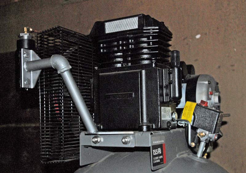
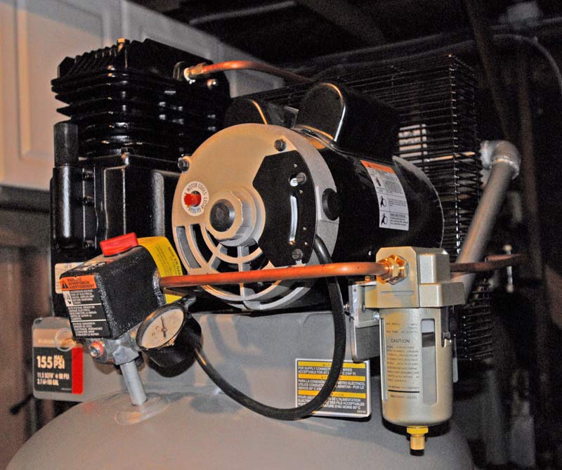
Just bought a Dewalt dxcm601 Air Compressor. Never had one this big before, in the past, I just rolled it up to an outlet, plugged it in. Turned it on, set the pressure regulator, and start using. I pick it up this Saturday (8/31/2019). I am in the middle of two big projects, one personal and the other at work. Not sure how long it will be before I can start setting it up. Since it will be permanently mounted, so to speak, there were some features that I wanted to look at. Plus there are a lot of parts that just come with smaller compressors that now I have to source.
I have and will keep searching, but I did want to pick you guys brain. Any lessons learned.

The dxcm601 is a 3.7 horsepower single stage 155 PSI.
Right now I am not too worried about the electrical. From charts, looks like 30amp should do it. The distance is only about 20 feet at the most, I have a bunch of 10 ga. Looks like I get to practice some more conduit bending. :)

Bolting it down:
Need rubber pads and Red Head bolts.

Delivery:
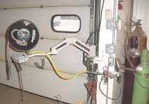
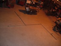
Looking at the Rapid Air for the delivery system. Some videos of guys installing 3/4" said they wished they went with 1/2" because the had to buy reducers. I know there are other options. Some cheaper guys swear they have never had an issue. I am willing to spend the extra for reliability and safety. There is not much price difference between 1/2" and 3/4" until you start factoring in adapters and 3/4" parts seem a magnitude more expensive. I thought I would just put the regulator at the end so I would not lose air over distance, although the distance is not that much, and convenient adjustments. Reading some of the Rapid Air specifications looks like 1/2" are limited to 150 PSI and 3/4" are 175 PSI. If I used 3/4" then I would not need a regulatory at the start.
Have not even started looking at regulatory and air filters.
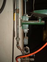

Auto Drain:
I have seen a lot of good things on the Tsunami Moisture Minder Auto Drain. Still learning about unload valves and signaling lines. I hope there is an easy one that I can tap into.
Here is a video, kind of long 17 minutes, showing it in use.
 
To avoid these ads, REGISTER NOW!
OP
P

penright

ALLIANCE MEMBER
Joined
Dec 27, 2016
Messages
618
Location
SW of Mustang, OK
Great Read
I did get it home yesterday. It may be sometime before I can install it, but I am looking for any thoughts on doing it. I am always open to learning lessons the easy way, asking. :)

1zt5WA89x_ZGM6gWZBqD62htTqBvK-3zjJ3DXCymiXYq6dPy7NlLHiLo5WS2-feK6A8lmu8BULAXVYZp1tVcbwbpeaNCItWrQ7W4BrAp0lff_d7TuV7eY8rn2VYuZFdiBfc3NHK1PsE1U0iv5WEYAIubBjgVGbGAja6TML7g6k9Der2jHM_S9ExFUonn4AmeYGQYQ779Dqercw1y9pxwP1BB-rL0UPpINfIFQrXg5r15UAolwBx5ciZ86ooJ7GnzHVUAF75u4sylGhqtCg_C-8YjdT4cvSl66IoPXybWDrhgMa_j34a5wGrGkQNyf9pK1HJVyrJvImj-yQMhVv2qvKMUaw-L4DWAoKWe3SMq06wk-bKOjx4vNYCp1EFVJAeiYaht8FPwZtjhclHbuxhJBaJAzw1pAtsJlUb6ElE9khlnv-WCk_GIUlDTHID6ybQ3kjEZ3TsSRnxqB8DqoqeyJsc7L4glQ9nwbkpDdEftpF-eo6NnyZBgM9fELfnAc9TQkw4mNYIYhi-Lick-PnKUnt41hHYNamIPPMvAhlgeNUJkZB-joBNEdtkZu9W64dBxPhq-ILLDgC4S4PD12459rFB-Av5yr7rmt-1dVK1p7AInOJWZQe48sl_RmNXBRsDXjRp3eQZkK8MkX8rOO65sHCYjabf8D-ZGPX3yM7Fuo6n0jLoR8KXQiFaEs9HfzC_lTRQQnj85ggUCoHQdgJzGFwAZ8MAmaG7kN5lkB6uz77lrgqs=w696-h927-no
 
OP
P

penright

ALLIANCE MEMBER
Joined
Dec 27, 2016
Messages
618
Location
SW of Mustang, OK
I do have a specific question. Any pneumatic auto drain using the sense line used to unload the compressor, assuming my understanding from googling is correct.

Is the small tube the one I want to tap into?
Any suggestions?


VoJnOEJ8p-fKwtDvdfRjcxqT0rpcEAluFmlHoVo7AnALsPhnjWBnEToTRpAfaQn3OYGcxhW8oUhYH-QtAZ7LPAutQBakwtO5lF-ceT4CUCUp69Ml2dny-_dCjeLCgUvZCs_fYX_0hQdreM55ibY4mzTV8kFwDoWH6pf2S7S7BvFMbt-sIUShBUzjVE5Ylqd5qDQRlppuI7tSu9pj2zK7Mf5G9RRTN7hiCkl3R4lYAWwXa1kEXr1gHCrRzJjxa67z-bh_YLly3MHTu9wrI-r3LjEt2pWhdtNwjCNfSdNB1B1y1-r3zSH_kj5FbgLFXuDhjCG-0aid_ZDyOYHy1iIwOIbNWlimjJ7ul0JVn8RNVHZhaiCnV1MhKa2-uQ_66p1GIWJOJ_xYlGa88myBJEGWGLiM90ntsuUIAJ7kVbZ0JBSYE11wXhmGYgqv9wyolObvZ1tswXzlDhg55MGwwNcao28_LGOrTIQBGIysJN9nyMO39VXrxJt3DwPhQzpfUcDIqDFYPJhPmwENAEYHMpXGBdSsjOEvGJWhaU7kFWX2_umrc53Sqh7s1p6sPO2tnFeiWltY9JShMNAscj4PamLOC-87Lrc7eNwrCxp495VdL5VfNUrGp76Gr50rKAbYvZcN9GEtOTVw0BUuES3qf2ivxpsR3trxiPp-HjLbtlCcOjgrBu2oybVWGqTFJcHvvxH_vq5_QaJnPhHeRONqhruNpI6UXMp1nU98jRpXnuvO_FhmtbE=w696-h927-no


If I wanted to disconnect it from the pressure switch, how does it come off? The other end at the tank looks like a compression fitting and just unscrews. The end with the pressure switch looks like it just pressed in. This seems like it would come out under pressure. Surely there is a secret handshake to get it off. Or does it come off with the switch? Does anyone recognize the setup?


XooeymquHy0nc7Emzcc_hSUrj_PSRPg0zYvhxTqkILLyTl6wFMFTgf_bxO5J-4D-T0PGPpphW4Nbt-Uf8RXWXQkD9wOHAh3qjNhd025sWM7fj19V_WRu4YpTSGkPb5v1IslptwAMqkFO2S0BUNgN1CIFju8vMtoPSRrGENGeMmhkJ1-RJBH5eGuBmQAPm-ffSpnedoXPD01iutsQgYK4buoEFK5pF_Z4Rt82JqBfb8IGcvC2UJQbM43jcxa5vpDZor0Cej4cBz2jPYCu23RrWG2xIxdBY6XsyzYxY7CbBzBaQoPwZKBZt_DqnbFPYbimkybS5kK23GI_invLzddacwNl1D7Xd7Unu23datKIEUO526B2qvnK9eyRs1iGj2zMTyjka0QERH64zZtlNzBxKaUsp08PUeN-ZNeQi0GjPxvd1CpUhizitdrtz8T3sqDiDwP_1r71flTAjjHZVqCOU128EaeTgLNeACMGTGkhBb3Cs469bhIayhY9bKkzRtvM32QAmtBBFI-RH5EF3PMFKLHUld2aBo_VrXNdW1Q7-wyRByWHulfrD36EvrygVY1ASdqLInRZKN8y9RH9bAOgndhBB43hVOqMJv30gC7fEtlnSwkuBfDN5BBuS0RsT6AdzHhaBU2MO954whP42fBNQ5_Sy9AWVB13ZlOFib57rrIAWXEPysgQwqlj2lgNEprBOsyh5x4ZByNVFFCWSUpm_sZ18ctmiJxknyYEO8PQCVG-7-8=w696-h927-no
 

The Tool Tyrant

ALLIANCE MEMBER
Joined
Dec 19, 2011
Messages
2,182
Location
Bonita, Ca. (San Diego)
Not familiar with that connection...strange. Here's an idea, at the check valve, remove the elbow that connects the pressure switch line and replace it with a tee. That will allow the existing line to stay unmolested.
 

dagofast

Well-known member
Joined
Oct 15, 2006
Messages
411
Location
The QC in AZ
The small line looks like it is inserted in simple push in fittings. The secret handshake you are looking for is to gently push the pipe in while also depressing that little sleeve around the pipe with the side of a flat blade screwdriver, then pulling the line out of the fitting.

But you have a much more convenient place to tap in at the front of the pressure switch, just remove the front facing plug.

I'm not sure how that will help you with draining condensation from the tank, but maybe I'm not following you.
 
Last edited:
OP
P

penright

ALLIANCE MEMBER
Joined
Dec 27, 2016
Messages
618
Location
SW of Mustang, OK
Here's an idea, at the check valve, remove the elbow that connects the pressure switch line and replace it with a tee. That will allow the existing line to stay unmolested.
One thing I was trying to understand was if that small line is the pilot signal I was looking for. You calling it a "check valve" means I am in the right neighborhood. I need the line that only has pressure when the compressor is running. I will explain more in the answer to @dagofast.


I'm not sure how that will help you with draining condensation from the tank, but maybe I'm not following you.

Here is a link to a video that may explain it better than I can here.
As I try and explain, remember most of the things I have learned about compressors is in the last week since I bought this one. My little Black Max ran for over 30 years. Actually is still running, just leaking from rusting from the inside. I did drain water from time to time, just maybe not often enough. I thought if I had an automatic it would help since I am old and forgetful. Since I am still learning anyone correct me if I misspeak.

Looks like there are two types of "automatic drainers". The first type is timer-based. By tapping into power to the motor, it will open a valve for so many seconds. So every pressure cycle you get a 5 -15 second air released.
The second is pneumatic. My understanding is air compressors have a line from the compressor's output so when the compressor shuts off, any pressure that could be still in the compressor is then let off. The automatic drain uses that signal to move a piston. There are two connections, one is from the drain the other is the signal. The drain side has a check valve, so at rest, the drain side is off. The other side of the check valve is an accumulator on top and drain port on the bottom. So when the compress starts, the pressure from the unload signal pushes the piston. It covers the drain port, opens the check valve. Any water then is pushed into the accumulator. When the compress shuts off and the air is unloaded from the signal, the piston returns opening the accumulator to the drain port. The pressure then blows out any water that is stored. Since the check valve is closed air in the tank can not escape via the drain port.

The advantage of the second method over the first is I don't have to find a 220v, 110v, or hack the 220v to get 110v for a timer-based system. Also, the air released is very small compared to a timmer based one.
 

mike93lx

ALLIANCE MEMBER
Joined
Dec 9, 2013
Messages
37,625
Location
Richmond, VA
Why would you want to drain the tank of air? Compressed air is very expensive to make and that holds a lot of it.

Any water drain needs to be at the bottom of the tank.
 

The Tool Tyrant

ALLIANCE MEMBER
Joined
Dec 19, 2011
Messages
2,182
Location
Bonita, Ca. (San Diego)
Tha line in question IS the line to your 'unloading pressure switch' which only carries air when the compressor stops, which triggers the valve in the pressure swich to open, allowing residual pressure between the receiver and pump to expel, allowing a load free start-up.
However, you need to get installation instructions as you need to direct the pressure that is expelled FROM the pressure switch to your new tsunami valve.
Perhaps someone here has installed one and can give more insight.
I have noticed that Champion Compressor now installs Tsunami drain valves.
 
Last edited:

ez-duzit

Well-known member
Joined
Jun 24, 2013
Messages
5,101
Location
Marina del Rey
I am installing what appears to be an identical compressor (but labeled "Porter Cable") and that same auto drain valve shown in the link, so am interested in your installation. In preparing the compressor I have already installed a heat exchanger to cool the air and remove some of the moisture. Will take some photos of that and post them here if there is any interest.
 

The Tool Tyrant

ALLIANCE MEMBER
Joined
Dec 19, 2011
Messages
2,182
Location
Bonita, Ca. (San Diego)
I am installing what appears to be an identical compressor (but labeled "Porter Cable") and that same auto drain valve shown in the link, so am interested in your installation. In preparing the compressor I have already installed a heat exchanger to cool the air and remove some of the moisture. Will take some photos of that and post them here if there is any interest.

Just to clarify, the "heat exchanger" or 'aftercooler' does not "remove" moisture, but rather cools the hot (steamy) air which causes the moisture to condense into droplets of water which then run to the bottom of the receiver where they can readily be drained off.
 

ez-duzit

Well-known member
Joined
Jun 24, 2013
Messages
5,101
Location
Marina del Rey
Actually the water trap inline between the heat exchanger and the receiver removes some of the moisture before it gets to the receiver.
 

The Tool Tyrant

ALLIANCE MEMBER
Joined
Dec 19, 2011
Messages
2,182
Location
Bonita, Ca. (San Diego)
Actually the water trap inline between the heat exchanger and the receiver removes some of the moisture before it gets to the receiver.

Interesting. I've only seen that once on a high dollar set-up, it was a black cast iron unit. If I recall correctly it ran around $800 for the unit so my interest stopped there!
Please post pics when you get her all complete.
 

Aileron

Well-known member
Joined
Apr 15, 2019
Messages
467
Location
outside
i believe the Industrail air and Dewalts are the same , just different colors. I just had a 60 gallon 2 stage industrial air IV5076055 delivered a few days ago for my home garage. It was actually a impulse buy. Replacing a 90's era Campbell Hausfield 5 hp single stage 60 gallon. Its been a good compressor but wanted to go to higher supply pressure. I have the 80 gallon in our shop for the last couple years made with the Dewalt name and although it isnt used full time it seem to work pretty good. I'm also wanting to replace the drain valve before I drop the compressor off its skid and will check out the Tsunami.
 

ez-duzit

Well-known member
Joined
Jun 24, 2013
Messages
5,101
Location
Marina del Rey
Here are a few photos showing my heat exchanger installation. The heat exchanger was purchased through Zoro; its mounts I fabricated from steel angle, stainless tube and galvanized elbows I had on hand. Water trap mount I fabricated from aluminum angle. All plumbed with copper tubing. Compressor was purchased from Tractor Supply.


dagofast

Well-known member
Joined
Oct 15, 2006
Messages
411
Location
The QC in AZ
One thing I was trying to understand was if that small line is the pilot signal I was looking for. You calling it a "check valve" means I am in the right neighborhood. I need the line that only has pressure when the compressor is running. I will explain more in the answer to @dagofast.


Here is a link to a video that may explain it better than I can here.
As I try and explain, remember most of the things I have learned about compressors is in the last week since I bought this one. My little Black Max ran for over 30 years. Actually is still running, just leaking from rusting from the inside. I did drain water from time to time, just maybe not often enough. I thought if I had an automatic it would help since I am old and forgetful. Since I am still learning anyone correct me if I misspeak.

Looks like there are two types of "automatic drainers". The first type is timer-based. By tapping into power to the motor, it will open a valve for so many seconds. So every pressure cycle you get a 5 -15 second air released.
The second is pneumatic. My understanding is air compressors have a line from the compressor's output so when the compressor shuts off, any pressure that could be still in the compressor is then let off. The automatic drain uses that signal to move a piston. There are two connections, one is from the drain the other is the signal. The drain side has a check valve, so at rest, the drain side is off. The other side of the check valve is an accumulator on top and drain port on the bottom. So when the compress starts, the pressure from the unload signal pushes the piston. It covers the drain port, opens the check valve. Any water then is pushed into the accumulator. When the compress shuts off and the air is unloaded from the signal, the piston returns opening the accumulator to the drain port. The pressure then blows out any water that is stored. Since the check valve is closed air in the tank can not escape via the drain port.

The advantage of the second method over the first is I don't have to find a 220v, 110v, or hack the 220v to get 110v for a timer-based system. Also, the air released is very small compared to a timmer based one.

Okay I watched the video and got an "Ahhh!" moment out of it. Now I understand how that type of drain works. Pretty cool concept and it sounds like it isn't exactly new technology by any means! It is a bit counter-intuitive at first glance because they routinely mount the drain valve higher than the bottom of the tank or water trap.

In answer to your specific question, yes, that small metal line should be your "pilot" signal. It isn't shown in the pictures but it looks like it is taken from the same manifold as the large output line from the compressor head to the tank. There should be a check valve at the bottom end of that large line to keep the tank air pressure from pushing back in to the compressor.
 
OP
P

penright

ALLIANCE MEMBER
Joined
Dec 27, 2016
Messages
618
Location
SW of Mustang, OK
I am installing what appears to be an identical compressor (but labeled "Porter Cable") and that same auto drain valve shown in the link, so am interested in your installation. In preparing the compressor I have already installed a heat exchanger to cool the air and remove some of the moisture. Will take some photos of that and post them here if there is any interest.

Yes, they look the same. If you read the fine print at the bottom the "Made in the USA", it says "with global materials". So the odds are good they are the same parts. Thanks for the pictures.
I think we can compare notes. so did you have to provide the tubing? Is the separator in the pictures automatic? I have seen a video of the Tsunami tee on the drain side. One went to the tank drain the other to a water separator. So it would use the signal to drain both.

I guess you have not run it yet. I was surprised about the 30 minutes break-in. Also, I have read to change the oil after the break-in run. That will get rid of any material let loose during the break-in. Not any different than we would do with a new engine. The DeWalt did not suggest changing the oil.

What are/did you do for air delivery system?

As mention in the OP, it may be some time before I can actually set mine up, but I am trying to be ready when the time comes.

More pictures and notes as you progress.
 

ez-duzit

Well-known member
Joined
Jun 24, 2013
Messages
5,101
Location
Marina del Rey
...did you have to provide the tubing?...
Is the separator in the pictures automatic?...
What are/did you do for air delivery system?...

The tubes I made from stock on hand.

The separator is automatic.

3/4" & 1/2" copper piping is being used for the delivery system, into which this compressor and my old Emglo pancake will be manifolded for redundancy, flexibility and extra capacity.
 
To avoid these ads, REGISTER NOW!
OP
P

penright

ALLIANCE MEMBER
Joined
Dec 27, 2016
Messages
618
Location
SW of Mustang, OK
It is a bit counter-intuitive at first glance because they routinely mount the drain valve higher than the bottom of the tank or water trap.
It took me a few times to visualize what was going on. Once I did it felt like a better system than timer-based. I figured if anyone has pros and cons it would be here.

Pretty cool concept and it sounds like it isn't exactly new technology by any means!
In the video, it talks about taking the idea from truck air breaks. I guess water for them could be bad in freezing weather. I don't know if they can get enough water to hydrostatically lock the breaks or not. Either way can't be good.


In answer to your specific question, yes, that small metal line should be your "pilot" signal. It isn't shown in the pictures but it looks like it is taken from the same manifold as the large output line from the compressor head to the tank. There should be a check valve at the bottom end of that large line to keep the tank air pressure from pushing back in to the compressor.
Your post prompted me to try and take some better pictures. So one of these fittings has to be the check valve. It has to be the one just above the tank. Then I am guessing where the pressure switch is where a valve is open to allow the bleed? You and the "The Tool Tyrant" have answered my question of where I need to tap. Between the small tube and elbow in the pictures. Now I am just trying to understand better. It kind of hard to see a check valve, they look just like fittings.
BTW, "The Tool Tyrant" it is hard for me not to think "Tim the tool time". Cool handle.


fAik5QUknuDD7Ycb2_dsTIfVQSJPOa54g3mrfeTodGfilgBZRV53uNJAytT-AVpnUEWx0bQvXlqs408TzLO0gOxzs1qp9YY5o3hlmzb8H00TRblU9zSuuHgVBdiELsgWlVqZgRmhfNHMZvn4QskXz3fsD2hBeOdUuDM6670mEn5ve3r4cRHODtLsSx0XmVxeGJV-_Sh18UHloyne4ZEZXQzo70JtlJGm7XXMfSZyswedUc4a2UJSJP0RUj0zdWBnLHYlB-69fe-hCezv2WyRaqBvJ4c76Ena13BZgpFAwGFUuOf4WLn3Q-TeiQjmeYJjOuiM7YLqwv62Qn6WlWG4f-K33y52tSMpGC3hXGghxlVigW1mNcukOUEykQNacLZBn0KAGaXhgKOhB2jpkI0VGtmWOpaM_VQfSFrTLudxPMTTwqcheA49w0_3lIm6Pp1zVVdokD3GZJHZeB7efizwA463Z7VCap9_U6y1XXQzGjemy0DTEYXq3iB_BWql4R1mVtB6iNgs6Q-dlbH9zmvNKt1MMgR3jVCdk5vzH-7Lk_Xc_ATv9x7yGAC-IVDifINLgS2u9Ql1IhbXyGCeKehlsGqBQyybV2PQF2r9RxvmXyOQjL_87W_rkPlNxCuzsf5NpGoqYufhW1H0ear5KLxSBotEQAU7L7swDj_pDvE6tLZkD1S1H0nMZaLBjq1BjlsH-vF4FkNzywsfZqt4RMQ7a8GZdn-jdHNi2mEt33q6mNlOvHc=w840-h878-no


gMqyCT0qo5EKKnE2Wklu0A46JynzXPLXoNk1hZJ1AnwX6npw2xBdli5X_J6ko95wcmIRd2t7rP3OAYk2MpG1pvDLXCQchq9uBDlBfSPlWo4GNTxyIhZW7-3m01pj0Hh2AP5h1GyROf4uuxZKe4JYdyPZAtLBbnnA3DZqglKS5H-ckZHCLsVv0KP5pwU-PkNyuLdDOMPMoCm6ouLzugNdwYkIHKubhPr2pv_E5YNOFR4o-1cF74svszVJ9fNUuqJgE22GkaZbV8VrjmwvxgCKFIw59_H6w-H-fKKDLMLPIZQZdUjgt9QMs9Ahe1ZPr3BTNBWppZKyWIRFRTtnWXh1DdI-fH0aXTfNBVOiAN6z1pm7Y1cjLIlIKgyZhK5n2NawYqvoxdhLYPyHDmQQ_hEKiEPla5hPXruhDd_MJFIGNWHsVhHyuoslGOJDNpUB9g7Y5STUWDc--ILINyLxtFdgcpJnXYVXrOV3_WrQOgMJsB_dtzj0fiQRus5TEjLCe836EvLO1m9D4KgZiLW2aw9Ip99e6T5YUovWZkOndlXAE8Uj9y61U84y5yNgeGgo2HIfkw3-ljcZMNj6M0k6n_P5c1ey8kktisEt-d4EoETFbD5EMVBL7H90lmko6gUMx0hLIyT4-ds2FKqXnZRQP5AVVXc8c2aGTsp4u0OdDwHHuE6I-otp9r8kJK1xrwauz-5m9SXXQoiwYnmeNesEHtF5dOyZOZBBe9mXWxfkQKCweppr4HM=w844-h879-no


xZW-y6tjlCoMW7ry-VYLUhgWNqK6Mx5g0SVD7qWraRYxsP3guQ6C7Djyt5C0OJfxKcgxsKJMJRyNH14mUW3x2PHLmdgsZribf7Cr820t3OUmcpFWXiiBuvzU4kLjgxonD8FJ8-gqm9zl4yC7JtLsddkBNh9c6SBpfoUmRFq3DK4Cxpf-dLE8uZSBolycxpglnFOavBMdppoPXlKBMjb_SjlHYNKYyj9Mf1G3L8bmD6ER9NFqvqbHcEJ5S3HCCERf-SKpjvvKHpGYQKEXTW3U58wMFimHegy1_qKa9ffRt-RGLjdl41VndqIp--bn1M9aYV6BXQxdw3_bgGREQb3eMPlRneylbNv1hJLYBijLNmBh2i2Kt_NTTt7EdCqXffh3z6OZBz301nHKekcqeSFCFWsTNsDJkUVX6ticQ0cKQdI3ftFLSoa3N-GSgDsx9jt__2oWor6BdvQDhKLzyXmgjHJba7x10fH_jG_41OShb4pTIBCpZiqCEKoVAn0JQiYCBHKNnNLnS0inaKh1f9oS9Mz7RltlYFFLwrIihHjVSU9zcYyH0pG30CHHRXyu7iCd1Rh4hQAp5j8m9QcUMO1nAtKRZc4FGi02tUsHm40DLD98Gbu2OW-cc1LHXmAsVAUp2gp6cqWLkJ4LlfV4AJToBzmYIvy9THiy906Cs12-sdfGBjTHmNQVruQ23fXxaAkafeB7gZ4nOKqlNOLOGXAQtZiphpApjP30sQNdAUmfUN-Ur0I=w609-h878-no
 

sberry

Banned
Joined
Jun 18, 2005
Messages
35,747
Location
Brethren, Michigan
My net is flaky today, getting tired of typing.
Ok. A couple of things. There should be basic 101 here. First,, forget about 1/2 of what you read. I don't care for auto drain. If it's not freezing a lb, ball valve to a hose plumbex thru the wall. Kick it open on occasion. Second, while all the new air pipe has its place I would rather not bother in a small garage. You do not need hydrants EVERYWHERE and they are a bad idea much of the ti.e or at least not a great idea. Make a simple manifold from so.e black 1/2 for some of it, to a good spot to put a fil/reg with a t after to add additional after you use this a little and find where it needs tailored.
If you use new type line you don't need every fitting they invent, only adapter to change to npt and use common hwd fittings. 1/2 does save on reduction.
Get 50 ft hose reel and figure out placement to get the most out of it. Put a convenience whip in after a bit if needed. Only quick couplers this need is at the tool end of the hose, this prevents unhooking of charged hose sections
 
Last edited:

sberry

Banned
Joined
Jun 18, 2005
Messages
35,747
Location
Brethren, Michigan
This can be a case of way too much info too soon
You went to the trouble of buying a highly engineered machine, designed to be as reliable, simple, plug and play as it can be,,, then,,,, we start fukkin with it, trying to get every idea we ever read added on before we even use it. First best thing is a ball valve, shuts it in, acts as a service disconnect for the piping. Start simple, 25 ft of hose to a fil/reg to a hose reel. Rig it so it can be used today. Nothing about it can't be changed later.
I don't mess with that rubber and redheads either. Lag or screw a little chunk of 2x4 to the foot, if it wants to walk lag the 2x4 to the floor. Mine has 1 tap con holding it in place, the backup none, sits on skids, actually both do so they can be moved pallet jack but not needed in most places
 
Last edited:

dagofast

Well-known member
Joined
Oct 15, 2006
Messages
411
Location
The QC in AZ
penright, Thanks for the better pictures! The check valve is inside the large fitting that is screwed in to the tank.

Just curious, is this compressor a single stage or dual stage?
 

The Tool Tyrant

ALLIANCE MEMBER
Joined
Dec 19, 2011
Messages
2,182
Location
Bonita, Ca. (San Diego)
Penright, I found the installatuon instructions online and I see that I assumed incorrectly. The Tsunami 'moisture minnder l' uses the constant pressure in the pressure switch signal line to keep the valve closed, then when the compressor cycles off and pump pressure is vented to the atmosphere, the valve opens and allows the condensate to drain.
That being said, to keep things simple, I would remove the 90 degree elbow where the pressure switch line attaches at the check valve and replace the 90 with a tee which would allow you to reattach the pressure switch line unmolested, then attach the new line to the Tsunami off the end of the tee.
Easy, peezy.
 

ez-duzit

Well-known member
Joined
Jun 24, 2013
Messages
5,101
Location
Marina del Rey
...to keep things simple, I would remove the 90 degree elbow where the pressure switch line attaches at the check valve and replace the 90 with a tee which would allow you to reattach the pressure switch line unmolested, then attach the new line to the Tsunami off the end of the tee.
Easy, peezy.

:) Easy for you to say. :)

Access to that easy peezy elbow is extremely limited due to there being only a rather small hole provided in the pump/motor mount welded to the tank directly above that elbow.
 
OP
P

penright

ALLIANCE MEMBER
Joined
Dec 27, 2016
Messages
618
Location
SW of Mustang, OK
I don't care for auto drain. If it's not freezing a lb, ball valve to a hose plumbex thru the wall. Kick it open on occasion.
That is not out of the question either. I am just doing my due diligence. I listen to you on the electrical and don't regret it. I just know my habits. It is kind of like my lawn irrigation. Most neighbors use hoses and pull sprinklers around the yards and they look great. Just for me sometimes I need a little automatic. :)

Get 50 ft hose reel and figure out placement to get the most out of it. Put a convenience whip in after a bit if needed. Only quick couplers this need is at the tool end of the hose, this prevents unhooking of charged hose sections
My current system is a 50ft reel and the compressor is right below it. I want to put the new one in a corner, so I will need to plumb over to the reel. I was not planning on buying the big kit, just enough so I don't have to mess with black pipe. I may put an outlet at the workbench. I was thinking about putting the regulator next to the reel and if put one by the bench. Not sure if I can use the regulator off of the old compressor for one of them. Nothing fancy, just thinking it will be easier to route.


If you use new type line you don't need every fitting they invent, only adapter to change to npt and use common hwd fittings. 1/2 does save on reduction.
I am a little concerned about using fittings not spec for air. I need to do some more looking, but more 1/2" seems rated for only 150PSI while 3/4" is for 175PSI. I am wondering if the added expense for 3/4" is for the higher PSI.


Thanks again, can always expect from you not only common sense but also no non-sense. :)
 

The Tool Tyrant

ALLIANCE MEMBER
Joined
Dec 19, 2011
Messages
2,182
Location
Bonita, Ca. (San Diego)
:) Easy for you to say. :)

Access to that easy peezy elbow is extremely limited due to there being only a rather small hole provided in the pump/motor mount welded to the tank directly above that elbow.

Unless the clearance between the platform and receiver is too small to reach the elbow from the end, it's an easier route. Use a crowsfoot on an extension to R&R the elbow. Been there, done that. :thumbup:
 
OP
P

penright

ALLIANCE MEMBER
Joined
Dec 27, 2016
Messages
618
Location
SW of Mustang, OK
Unless the clearance between the platform and receiver is too small to reach the elbow from the end, it's an easier route. Use a crowsfoot on an extension to R&R the elbow. Been there, done that. :thumbup:
That is where the tap needs to be. Just like anything in a hole, you just what to fiddle till you figure it out. I think a guy has to come from the top. From the side, a wrench long enough, even stretching your fingers in, would be too long to get a good stroke.

I was kind of hoping someone would have done this before and could even give a parts list.
 

The Tool Tyrant

ALLIANCE MEMBER
Joined
Dec 19, 2011
Messages
2,182
Location
Bonita, Ca. (San Diego)
That is where the tap needs to be. Just like anything in a hole, you just what to fiddle till you figure it out. I think a guy has to come from the top. From the side, a wrench long enough, even stretching your fingers in, would be too long to get a good stroke.

I was kind of hoping someone would have done this before and could even give a parts list.

Penright, a crowsfoot on an extension works great to reach the elbow from the end if you can't access it from the top :thumbup:

Look at the install instructions here...

https://filters.com/wp-content/uploads/osc/PDFs/moistminddeluxeinstall.pdf

BTW, they sell an install kit with fittings. :beer:
 

sberry

Banned
Joined
Jun 18, 2005
Messages
35,747
Location
Brethren, Michigan
I use a thread like this to remind myself to walk over and kick the valve open to the drain on occasion. I don't do it every fay or even weekly but somewhat based on run time and use. Nothing scientific but a guy can get the feel for it. Its not something to worry about and its the way it was done for decades.
The factory petcock is there for exposure to freezing weather. There is no "sump" effect to the fittings or place to trap water and freeze till bust. The water sitting in the bottom doesnt expand the tank, just sits till it thaws and can be drained.
I have a couple fixed whips and reels. You can run several items off a regulator, have even back plumbed a little to do it. Have one with 5 outlets on it.
Common steel hwd fittings are good for air, they may list the pressure on them to coincide with some valves, not sure why but have had them on 1500# hydraulic, lots of them, some 2000#. Its not something to worry about. I like a few places/things I can modify easy,,, the easiest way to get it "right" is often to build and use and find out after you could have done it differently,,, and donr be scared to do it twice. We hear it a lot here, the future proof, the extra shite just so "I don't wanna do it again"
ilike removing a fitting and turning it is the end of the world when it is often the easier softer way to get it to work correctly vs trying to pre engineer it all and speculate on every scenario.
Some of my suggestions are starting points, nothing that cant be adapted later. We have seen many threads here,,, I was going to fix it better,,, now how do I fix this factory fitting that was fine till they fukked with it.
We see a thread on occasion with failed auto drain. Hard to beat the reliability of a ball valve and opening it on occasion with operator right there. Same for shutting it in. If the comp is working fine it wont run without leaks, my bud has one holds for years, to shut in shut off the service valve at tank and its a done deal.
Last pic is an outside apron I use in nice weather, don't even have an outdoor, the reel turns and reaches out when the door is open. Got one reaches out the back the same. Actually removed and didn't feed an old hydrant I abandoned during a renovation. Out the front have a port with a reel for tire air.
 

Attachments

  • air 3.jpg
    air 3.jpg
    78.8 KB · Views: 53
  • air hose reel.JPG
    air hose reel.JPG
    33.7 KB · Views: 47
  • air pipe 2.jpg
    air pipe 2.jpg
    115.2 KB · Views: 44
  • air comps rev.jpg
    air comps rev.jpg
    95.3 KB · Views: 48
  • A frame hoist walk thru.jpg
    A frame hoist walk thru.jpg
    89.7 KB · Views: 49
  • air 4.jpg
    air 4.jpg
    71.1 KB · Views: 48
Last edited:

sberry

Banned
Joined
Jun 18, 2005
Messages
35,747
Location
Brethren, Michigan
Something else. While it often seems simple,,, and it can be one of the reasons to not "void the warranty" is not only damage to a unit but safety and often systens are carefully integrated to work with each other from the factory,,, and being simple can be part of that.
I might try to think of specific examples such as additional wiring added etc but there is often stuff done that doesn't even occur to us as being part of a system or they found after forensics parts that fail especially in models made for long time. I remember I had a suggestion or 2 for engineer at a trade show and he kind of looked at me and wonder what tree I fell out of,,,, it was due to the fact they make this for 40 or 50 years under engineering and my thoughts were far from original. If they thought a comp needed several more switches, lights and valves they would put them on at the factory or offer them up as additional equipment,,, they really hope the end user simply follows the instructions and good common practice instead of trying to re invent the thing which seems to be a trend with many first time owners of this type of equipment.
 

sberry

Banned
Joined
Jun 18, 2005
Messages
35,747
Location
Brethren, Michigan
All those fittings been factory installed, sealed, tested etc. Maybe some later date would make a change if I had to but would try to see how it all worked first as it was designed. Only 2 things I would be tempted to change is easy drain method and ball valve at the tank.
 

gungatim

Well-known member
Joined
Jan 8, 2013
Messages
8,101
Location
west mich
That is where the tap needs to be. Just like anything in a hole, you just what to fiddle till you figure it out. I think a guy has to come from the top. From the side, a wrench long enough, even stretching your fingers in, would be too long to get a good stroke.

I was kind of hoping someone would have done this before and could even give a parts list.

The one I installed I just cut the unloader line and spliced in a Tee for the auto drain. my kit came with the nylon line and the fittings, but since your line is aluminum, you'll need to use compression fittings to install the tee.

don't know what brand auto drain you are looking at, but if it's like most of the generic kits out there (HF, etc.) they only work when the compressor cycles on/off, and don't necessarily drain ALL the water out of the tank. just a portion that fills the valve. I still have a manual drain I use occasionally that gets the rest out.
 

sberry

Banned
Joined
Jun 18, 2005
Messages
35,747
Location
Brethren, Michigan
I have 3 tanks, 2 comps. Found old pieces of water line from a demo, flares, nuts all done cept 1, hook them to a common hose thru the wall and ball valves on tanks.
 

Attachments

  • air plugs.JPG
    air plugs.JPG
    50.6 KB · Views: 28
  • comp drain.jpg
    comp drain.jpg
    116.2 KB · Views: 32

sberry

Banned
Joined
Jun 18, 2005
Messages
35,747
Location
Brethren, Michigan
You can see it all tied together. The big blue is a backup/demand I put back together from a basket, I actually leave the breaker off but that and the main fed to the receiver which is plumbed out the top with a semi modified fitting to the manifold. The nlue gets only a little water and I suspect it might be even less if I change the plumbing a bit bot most in the main and receiver. The receiver is piped to the manifold and the hyd hose coming off it is a 1 hydrant circuit for my bench and allows for shut down of the rest of the building air independentl I have 1/2 hyd hose from comps to receive with valves on each end, I can totally isolate either comp and the tanks from both feed the receiver. Parallel feed so to speak for demand.
What big and efficient connectors do well is let them be added in series, sections of hoses and t's.
 

Attachments

  • air comps rev.jpg
    air comps rev.jpg
    95.3 KB · Views: 33
  • air comps air.jpg
    air comps air.jpg
    148.7 KB · Views: 34
  • air fittings.JPG
    air fittings.JPG
    39 KB · Views: 28
Last edited:

sberry

Banned
Joined
Jun 18, 2005
Messages
35,747
Location
Brethren, Michigan
In a small shop can get by with a single service valve and 1 fill reg. I have some redundancy, some convenience and have service valves ahead of regs. 1 part can be shut off without effecting the rest and it makes it easy to turn off a couple old hose reels when not needed.
The plasma started an air leak the other day, I wanted to wait till winter to check it out, very minor and intermit but I thought,,, ah ga,, I pulled out the quick connect and put a valve between it and the t,,, just shut it off if it leaks.
For Penwright and others doing setup, get what you need as you need it, get it if you need it but don't go wild speculating about every what if, will end up with a box of fittings you store in the end. You can use a hose, in fact buy a 50 ft 1/2 hose, a 3/8 would work even with factory fittings and screw all this together and see where it lands. I finally finish a run about 4 years old because I wanted one of my hoses back
 
Last edited:
Status
Not open for further replies.
To avoid these ads, REGISTER NOW!
Top Bottom