
You are using an out of date browser. It may not display this or other websites correctly.
You should upgrade or use an alternative browser.
You should upgrade or use an alternative browser.
New Millscott project
- Thread starter royce
- Start date



Amazing work Royce. With consideration to the amount flips, turns and full gainers you had to do being close enough that just a bit of honing cleaned up the issue is nothing short of outfuckingstanding!!
A half a thou here and there can really add up. You da man
A half a thou here and there can really add up. You da man


RoninB4
Well-known member
Looking forward to the full assembly because I still don't grasp the design. I have to start with a full design concept in mind and then work backwards to create the components. I'm kinda dumb that way. Always like seeing the work of others, especially when it's better than my own.

RoninB4
Well-known member
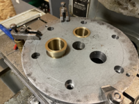
Bored the dynamic jaw plate for the first guide bar.
I was shooting for a light press fit, but overshot it.
Ended up with a slip fit.
-A slip fit might be better for assembly/testing, you can always use some Loctite green (bearing retainer) on it when you're sure it will work the way you want it to and/or if painting is done after initial fit-up testing. Just a suggestion, have a couple more if you want.
Yes, locktite or welding the pins to the jaw plate was my thoughts, We'll see after it all assembles, and function is checked.-A slip fit might be better for assembly/testing, you can always use some Loctite green (bearing retainer) on it when you're sure it will work the way you want it to and/or if painting is done after initial fit-up testing. Just a suggestion, have a couple more if you want.
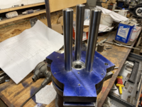
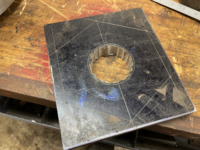
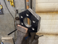
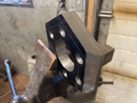
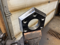
Finished up the thrust bearing cap.
Bored, drilled and countersunk.
Cut to shape with a portaband, dressed with a 4-1/2" side grinder, then grained with a belt sander
Bored, drilled and countersunk.
Cut to shape with a portaband, dressed with a 4-1/2" side grinder, then grained with a belt sander
Attachments
-
 tempImageIm7hz8.png3.2 MB · Views: 97
 -
 tempImageMgaUpe.png2.4 MB · Views: 88
 -
 tempImageG3VTRl.png2.2 MB · Views: 87
 -
 tempImageGKh8bY.png2.5 MB · Views: 88
 -
 tempImagegYyDSr.png2.3 MB · Views: 95
 -
 tempImagenG1nOV.png3.1 MB · Views: 104
 -
 tempImagex0T0T4.png2.7 MB · Views: 104
 -
 tempImageufhXIs.png2.8 MB · Views: 125


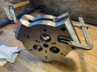
You win some and you lose some.... today was not your day....Got the 8" and 5" jaws let into the dynamic jaw plate, after busting a tap.
I guess I had it coming, for using a dull tap.

Lynn
RoninB4
Well-known member
-They work right up until they don't. Sometimes I'll grind off the tip up to the first full thread or two if it doesn't feel right and I'm desperate. You can also see a dull tap begin to "wind up" a bit. Tap brand? Just curious.I guess I had it coming, for using a dull tap.
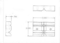
Had a good chat with my partner Kevin about the 3" jaw design, today.
They will have a rabbet cut in the top, 2 ea horizontal V- grooves and 1 ea vertical v-groove.
I'm tickled that Kevin will be making them at Millscott East.
I sketched a rough concept and Kevin drew it up proper, with some needed changes.
He also schooled me on tap drill size, thread class and tap design.
I can't count how much I've learned from him, through the years.
Finished up letting in the 3" jaw on the dynamic jaw plate and drilled the screw holes.
They will have a rabbet cut in the top, 2 ea horizontal V- grooves and 1 ea vertical v-groove.
I'm tickled that Kevin will be making them at Millscott East.
I sketched a rough concept and Kevin drew it up proper, with some needed changes.
He also schooled me on tap drill size, thread class and tap design.
I can't count how much I've learned from him, through the years.
Finished up letting in the 3" jaw on the dynamic jaw plate and drilled the screw holes.
Attachments


paulsomlo
Well-known member
Are you doing all the milling on the Moore?
PugetDude
ALLIANCE MEMBER
This vise (like the first one) belongs in the Alasksonium. Absolutely awesome work again Royce; you and Kevin make a great long distance design/build team.
Looks like you got lucky with the tap breaking off above the surface… mine usually break off below the surface where it’s a ***** to get them out.
Looks like you got lucky with the tap breaking off above the surface… mine usually break off below the surface where it’s a ***** to get them out.
Thanks Puget, I sure enjoy our collaborations.This vise (like the first one) belongs in the Alasksonium. Absolutely awesome work again Royce; you and Kevin make a great long distance design/build team.
Looks like you got lucky with the tap breaking off above the surface… mine usually break off below the surface where it’s a ***** to get them out.
Yes, luckier than a two peckered dog


PugetDude
ALLIANCE MEMBER
Royce, I must have missed it but where are you doing all this machining? Home or at work? ( not many jig borers in home shops)
Looks great, looking forward to the rest of the build.
Looks great, looking forward to the rest of the build.
Home shop Puget, the jig borer was made in 1969 and came from the University of Alaska.Royce, I must have missed it but where are you doing all this machining? Home or at work? ( not many jig borers in home shops)
Looks great, looking forward to the rest of the build.
It came up for auction awhile back and nobody bid on it, lucky I am.
Thank you
Royce
Attachments

Last edited:


paulsomlo
Well-known member
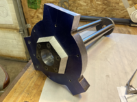
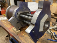
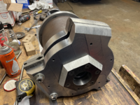
I'm still having a hard time conceptualizing how this is going to look and mount to a bench. Or is it going up with the space shuttle?
It won't be mounted to a bench, it will mount to a stand.I'm still having a hard time conceptualizing how this is going to look and mount to a bench. Or is it going up with the space shuttle?
There is a couple concept sketches of the stand on the first post of this thread, that may help understanding.
PugetDude
ALLIANCE MEMBER
The space shuttle doesn't have the payload capacity for this one.I'm still having a hard time conceptualizing how this is going to look and mount to a bench. Or is it going up with the space shuttle?
paulsomlo
Well-known member
So, it's for holding the space shuttle?The space shuttle doesn't have the payload capacity for this one.


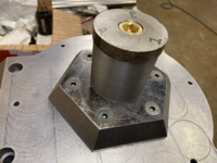
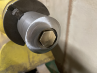
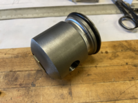
Spindle end progress.
Swapped out the brass flush plug with a hex plug for aesthetics.
Radius'd the end on the wood lathe with a side grinder [Kevin Scott trick #39]
Cut an o-ring groove to keep trash out of the thrust bearing.
Cut another groove to slough debris away from the spindle.
Swapped out the brass flush plug with a hex plug for aesthetics.
Radius'd the end on the wood lathe with a side grinder [Kevin Scott trick #39]
Cut an o-ring groove to keep trash out of the thrust bearing.
Cut another groove to slough debris away from the spindle.
Attachments



PugetDude
ALLIANCE MEMBER
You might be able to knurl the pins to increase their diameter where they go into the bore to tighten up the fit- or peen the bore a with a sharp ***** punch in evenly spaced increments- (I like to use a couple of rows) then press the pins into the upset bore. Loctite if necessary.Yes, locktite or welding the pins to the jaw plate was my thoughts, We'll see after it all assembles, and function is checked.