Thanks Puget, if there is too much deflection in use, I'll do something along those linesYou might be able to knurl the pins to increase their diameter where they go into the bore to tighten up the fit- or peen the bore a with a sharp ***** punch in evenly spaced increments- (I like to use a couple of rows) then press the pins into the upset bore. Loctite if necessary.

You are using an out of date browser. It may not display this or other websites correctly.
You should upgrade or use an alternative browser.
You should upgrade or use an alternative browser.
New Millscott project
- Thread starter royce
- Start date

RoninB4
Well-known member
Shape of the screw? Acme, modified Acme, Square, Butress? Idle minds want to know....
Looking good Royce.
Looking good Royce.
RoninB4
Well-known member
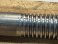
Acme
-An excellent choice sir. Rolled instead of cut.....?

PugetDude
ALLIANCE MEMBER
Hard to beat an Acme thread for this application. Fast acting, good clamping force with little turning effort.
Worked on the spindle today.
After second guessing myself for an hour, cut and faced the spindle down on both ends.
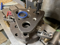
Drilled a pocket for spring and ball detent on the jaw end.
Turned the tail end down to bushing diameter and drilled and tapped the end, 3/8-16 for an end stop and thrust washer.
After second guessing myself for an hour, cut and faced the spindle down on both ends.
Drilled a pocket for spring and ball detent on the jaw end.
Turned the tail end down to bushing diameter and drilled and tapped the end, 3/8-16 for an end stop and thrust washer.
Attachments




matt_i
Well-known member
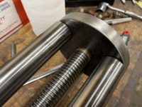
Fantastic and I'm looking forward to every update! Did you buy the bronze block pre-tapped in Acme or did another shop do that for you? Making that one internal thread is a pretty challenging detail...I've had some various vise-fab dreams and that's where I always get stuck. Acme can be tapped but requires a multi-stage affair to get it working correctly...Single point or CNC thread milling seems like a more reasonable solution.
Thanks Matt,Fantastic and I'm looking forward to every update! Did you buy the bronze block pre-tapped in Acme or did another shop do that for you? Making that one internal thread is a pretty challenging detail...I've had some various vise-fab dreams and that's where I always get stuck. Acme can be tapped but requires a multi-stage affair to get it working correctly...Single point or CNC thread milling seems like a more reasonable solution.
The screw and nut came from an outfit called Dependable Acme, they are in New York.


After discussing with Kevin about the finer points of silver brazing, here is the joint criteria and brazing procedure.
The spindle is 1.249 Dia.
The bore is 1.255 Dia. x 1.60 deep
This leaves an annular space of .003
That calc's out to .0189 cu in which equates to about 6" of 1/16 56% silver solder.
Preformed a 7"coil of solder to rest on the shoulder of the end bore.
Slathered the bore and spindle with white brazing flux prior to assembly.
Having not silver brazed anything with this much mass, I was a little concerned about getting enough heat on the spindle inside the knob end, without burning the flux.
Used 2 weed burners for both the initial preheat and to bring the knob end up to temp.
The spindle was heated with a #6 welding tip.
The joint was heated to temp, until a ring of solder could be seen at the bottom of the joint.
Then rotated the joint 1/2 turn, while continuing to heat, adding another couple inches of solder at the top of the joint.
It went well and I feel that this a good stout joint
The spindle is 1.249 Dia.
The bore is 1.255 Dia. x 1.60 deep
This leaves an annular space of .003
That calc's out to .0189 cu in which equates to about 6" of 1/16 56% silver solder.
Preformed a 7"coil of solder to rest on the shoulder of the end bore.
Slathered the bore and spindle with white brazing flux prior to assembly.
Having not silver brazed anything with this much mass, I was a little concerned about getting enough heat on the spindle inside the knob end, without burning the flux.
Used 2 weed burners for both the initial preheat and to bring the knob end up to temp.
The spindle was heated with a #6 welding tip.
The joint was heated to temp, until a ring of solder could be seen at the bottom of the joint.
Then rotated the joint 1/2 turn, while continuing to heat, adding another couple inches of solder at the top of the joint.
It went well and I feel that this a good stout joint
Attachments


PugetDude
ALLIANCE MEMBER
That is really a professional looking silver brazing job, Royce.
I haven't brazed anything since High School; and mine didn't look anything like this then.
I haven't brazed anything since High School; and mine didn't look anything like this then.
Thanks PugetThat is really a professional looking silver brazing job, Royce.
I haven't brazed anything since High School; and mine didn't look anything like this then.
I was apprehensive about it, but it went better than planned.
Now we'll see if it comes off in my hands under load!
PugetDude
ALLIANCE MEMBER
I just don't know how to respond to this.Now we'll see if it comes off in my hands under load!
Scott
KMScott
Well-known member
Looks real good Royce. Nice seeing the braze underneath like that. Such a fun project.
Shiftless
Well-known member
Fantastic work you guys…what a team!
(Need to heat up a big chunk of metal? Just set it up in between 2 weed burners! The term “cross-fire” comes to mind)
(Need to heat up a big chunk of metal? Just set it up in between 2 weed burners! The term “cross-fire” comes to mind)


RoninB4
Well-known member
Looks great, does it meet your expectations? Howzabout the intended mounting location?
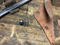
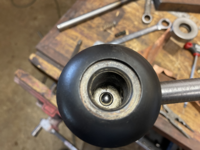
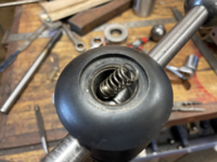
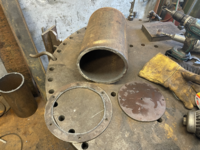
Fit and installed the springs on the detent balls, installed the pin wipers in the bearing cap, Installed O-ring on spindle knob.
There was a noticeable increase in friction with the pin wipers.
The spindle drag with the O-ring installed is too strong, so I'll replace it with a smaller one.
There was a noticeable increase in friction with the pin wipers.
The spindle drag with the O-ring installed is too strong, so I'll replace it with a smaller one.
Attachments



PugetDude
ALLIANCE MEMBER
For the first time ever I’m a bit disappointed Royce. Your guide set up is just too damn gorgeous to cover up. Now toss that cover in the scrap heap and make a lexan shroud
Yeah. It looks pretty light duty anyway…
PugetDude
ALLIANCE MEMBER
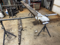
Dug some tube out of the snow bank for the stand.
96 here today…


Had 85 here today.... supposed to be down to 45 by next Monday... RollerCoaster weather pattern!!!Hey, it hit 40 at my place today, loving me some long warm days.
Lynn
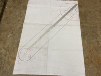
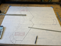
This stand is not like any I have seen or built.
The dual columns pivot at the base as well as at the vise.
This is to make the elevation adjustable.
Anyhow, got the column and base geometry hammered out and dimensioned today.
Need to figure out the bearings on the pivots next.
The dual columns pivot at the base as well as at the vise.
This is to make the elevation adjustable.
Anyhow, got the column and base geometry hammered out and dimensioned today.
Need to figure out the bearings on the pivots next.
Attachments

WoodsTruck
Well-known member
- Joined
- Jan 12, 2013
- Messages
- 1,040
Looking forward to the mount.
You will have the clamping surface set up to have the vise flat as well as vertical?
You will have the clamping surface set up to have the vise flat as well as vertical?
And this instantly popped into my tiny skullYes and any angle in between
