
You are using an out of date browser. It may not display this or other websites correctly.
You should upgrade or use an alternative browser.
You should upgrade or use an alternative browser.
New Millscott project
- Thread starter royce
- Start date


WoodsTruck
Well-known member
- Joined
- Jan 12, 2013
- Messages
- 1,040
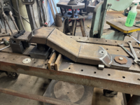
It's amazing. Living life through your camera lens didn't do the size of this project justice until you start mating up the pieces and reality starts to sink in on how large this thing will eventually be.
PugetDude
ALLIANCE MEMBER
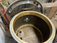
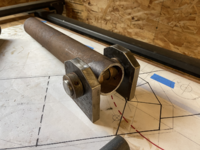
Without a way to indicate and line bore the axle assembly you’ll probably have to hone the bores to get your axle to slide through. I’d probably jig it like you are doing with a sectional dummy axle on the bores that would allow for easy disassembly after welding. Weld, drive the dummy axle out, then hone to get the real one to slide in. Stub axles would make this a lot easier if your design permits.
Project is looking awesome!
Scott
Project is looking awesome!
Scott
Scott, they are stub axles, pressed into the hub.Without a way to indicate and line bore the axle assembly you’ll probably have to hone the bores to get your axle to slide through. I’d probably jig it like you are doing with a sectional dummy axle on the bores that would allow for easy disassembly after welding. Weld, drive the dummy axle out, then hone to get the real one to slide in. Stub axles would make this a lot easier if your design permits.
Project is looking awesome!
Scott
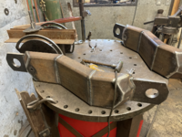
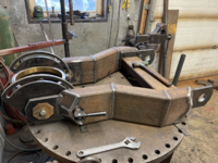
They will be welded to the inside of the hub.
I'm banking on the machine work to the hub being true, if that proves to be off, I'll have to open up the bearing bores in the ears to help correct.
At least, that's what I'm thinking.



PugetDude
ALLIANCE MEMBER
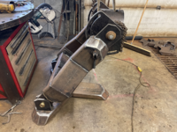
That thing is a beast, Royce. I wasn't really visualizing the scale until this last batch of pictures.
Awesome work!
Awesome work!
+1BEAST!!!


PugetDude
ALLIANCE MEMBER
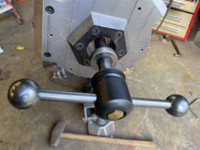
Pretty good haul, Royce. Can't wait to see what you do with the handwheels and the landing gear.Went on the hunt for a spring today, no luck.
Did find a 5 ton ball screw jack on a surplus lift and landing gear for a high deck.
Should be able to make one or the other work.
Like the Vise-grip ground clamp. I should do something similar.
I have high hopes the ball screw jack can work in this application, it is so smooth.Pretty good haul, Royce. Can't wait to see what you do with the handwheels and the landing gear.
Like the Vise-grip ground clamp. I should do something similar.
The ratchet mechanism is backwards, If I'm thinking right, the worm gear can be swapped end for end to change force direction.
Nothing more irritating than a bum ground, the vise grips stop all that ****.
Attachments




PugetDude
ALLIANCE MEMBER
Royce, now you're just showing off...
2 anvils?
Seriously?
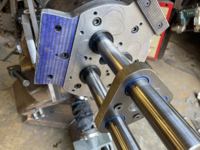
Looks amazing; incredible machining and fabrication skills on full display.
2 anvils?
Seriously?
Looks amazing; incredible machining and fabrication skills on full display.

txvwnut
Well-known member
So now that the prototype is done when will the production begin on a consumer version, and will there be a pre-production sale.
That thing is cool as hell.
That thing is cool as hell.
Jayman17
Well-known member
That is an awesome vise and stand Royce, I’d say that is quite the accomplishment even by someone as talented as you. Any plans for retractable casters?
Jay
Jay
WoodsTruck
Well-known member
- Joined
- Jan 12, 2013
- Messages
- 1,040
I'm not sure how big the fish are in Alaska, but that is a healthy fly tying clamp.

PugetDude
ALLIANCE MEMBER
What are your plans for it now that it’s finished, Royce?
Heck yea and thank you.
Top of jaws 30" to 48"
Ya know, you're missing one last item.
An detachable auto leveling linkage.


James-W
Well-known member
I must say that is one heck of a vise. I give you top honors for originality, craftsmanship, and for being incredibly creative. I think you have a real winner and if I were in a position to do so, I would give you a prize. But that being said, I don't think it is something that would be marketable. What I mean is, with all the highly machined parts and all the heavy duty parts, I am guessing the vise would likely sell for somewhere around the $4K to $5K dollar range. I doubt many people are going to want to spend that much money on a vise, even one as well made as this one is. But it sure looks cool and I bet it works even better. Kudos on that job, you outdid yourself.
James-W
Well-known member
The two of you sure make a great team and there is no question about it, you do marvelous work. My hat is off to both of you.Thank you James,
It was not built for market, but for the sheer joy of creating.
Kevin and I started chatting about this project around 6 months ago and to see it now is so fun.
It was a huge challenge and my partner is the finest kind