To avoid these ads, REGISTER NOW!

Not Rocket Science...

matt_i

Well-known member
Joined
Mar 14, 2008
Messages
10,722
Location
SE Michigan
This is very cool and will be very useful in the future! I had never considered inverting standard trolleys to be the bogey wheels :thumbup:

So here's an idea to pollute your mind...:D

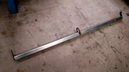
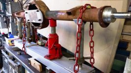
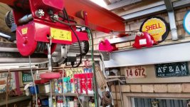
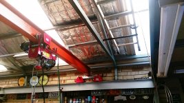
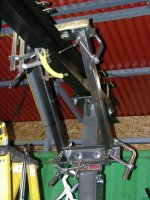
Consider you are almost to the point of having a power-travel bridge. You just need a long shaft which could be a tube like even a thinwall conduit for the loads involved and some traction wheels of same OD...could be caster wheels or the like.

You can drive it from anywhere but center would be best to equalize the torsion. If you find the proper chain sprocket you can slip it on and weld it into best position. There have to be some supports for the long shaft but they don't need to hold a lot of weight. Some simple tube steel arms.

You mentioned VFDs and gearboxes, you don't need an exotic VFD, just a 1/4hp motor will do this job and some reduction, some via the chain drive and some via the gearbox and some via the VFD. Its a perfect application to go after two or three travel speeds via setpoints programmed into the VFD itself....just have to have it respond to the proper button or input.

In any case you'd have a crane up there with the big boys and you wouldn't have to worry about racking. A big crane would have more distance between the end trucks but this costs you access to things set near the walls.

Keep the pics coming please, fantastic build!
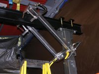
 
To avoid these ads, REGISTER NOW!

Old Man Roger

Well-known member
Joined
Apr 6, 2017
Messages
17,409
Location
Palm Coast Florida
Thanks Roger, a point worth considering since it ain't difficult to do.
What I have discovered so far is the need to keep the trolleys in unison, so one does not het ahead of the other a cause some sort of racking.
They both need to remain at 90 degrees to the track as well as the gantry beam at all times.

Here is a pic of my cheap *** bump stop, of which I need 4, being one at each end of both tracks.

I also needed to add to the end of one track some steel angle bolted to the center web of one of the tracks to ensure there was no possibility that a trolley could over run the end of the track and fall.
Only one scenario for that as the other 3 track ends terminate against very solid other members should the bump stop fail.

Next step is to install my winch and get power similar to my previous pic's for the tracks, but to the gantry beam now.

Sorry if any of my pic quality is a bit off, I had glare and sometimes darkness issues which I have tried to improve with my auto correct function...

Would increasing the length of each dolly help with racking?
 
OP
F

fiftyv8

Well-known member
Joined
Dec 29, 2018
Messages
237
Location
Perth
Thanks Matt_i, I am doing my best.
So far things are falling into place considering this is a proto-type for me.
I did spend a lot of time figuring and measuring etc.

What I did not mention, mostly because it was no fun, was that I had to remove a section of other old roof support stuff, most of which was left over from the old roof structure, sounds simple, but bad luck for me was that some of these members carried services such as power lines and I have reticulated air lines that also run in that roof space.

That is actually one reason why the big main beam I mentioned at the start of this thread remained in the roof space.

The other thing that I have had to think about and move around was lights.
Everything looked pretty clear but once I considered the traversing of this unit which will move in about 16 feet in two directions, there was a few items that needed to be removed or relocated.
 
Last edited:
OP
F

fiftyv8

Well-known member
Joined
Dec 29, 2018
Messages
237
Location
Perth
Roger, I did consider that, when everything was still on the ground, but once I got things connected up in the air, it became very obvious to me that racking was only going to be minimised/eliminated by the solid strength of the connection between each trolley and the gantry beam.

I have minimised this issue by adding a small flat bar gusset at each trolley end with the gantry beam and it seems to be doing the job.

The other thing that became obvious and fortunately that occurred before things were put together and up in the air, was the fact that there was going to be a strong possibility that the level between the two tracks may not be absolutely perfect.

So I built in a kind of moving joint at the trolley to beam connection at one end only in the hope that if there was any slight mismatch of levels there was going to be a point that would allow things to have a little bit of flexibility during traversing.

Its tricky as it is supposed to be a simple gantry and not ROCKET SCIENCE, but small things start popping into your mind as it starts to come together.
I am trying not to over think it.

Plus any changes or mods are going to be a big pain in the *** up 9+ feet of the ground.
 
OP
F

fiftyv8

Well-known member
Joined
Dec 29, 2018
Messages
237
Location
Perth
Matt_i, as for your idea of additional driven movement it sound great, but for now I think I will remain satisfied with what I am about to have here.

A third driven direction would definitely be a luxury I could live with and you have provoked my thinking, but for now I must focus on the tasks at hand.
It would definitely need to be electric and the idea of various speeds would be a real necessity to make it functional.

For what I have now, I expect to just be using a primitive pull chord to move the two trolleys forwards and backwards...
 
OP
F

fiftyv8

Well-known member
Joined
Dec 29, 2018
Messages
237
Location
Perth
Roger, I used a heavy duty gate hinge to give one trolley a little up and down movement if there was anywhere that the two beams did not quite align.

Both beams are as level as I could possibly get them, but could be a whisker off level with each other, meaning one track could be slightly higher or lower than the other.

Also a pic of the flat bar brace, it is nothing spectacular, but did make a huge difference to locking in that perpendicular effect that I needed at both trolleys.
 

Attachments

  • Girder Gantry (39).jpg
    Girder Gantry (39).jpg
    69.6 KB · Views: 87
  • Girder Gantry (42).jpg
    Girder Gantry (42).jpg
    75.3 KB · Views: 90
OP
F

fiftyv8

Well-known member
Joined
Dec 29, 2018
Messages
237
Location
Perth
fiftyv8 - that gantry crane is bad ***!

Thanks Larry, I live in hope that it will be very much more versatile than a floor crane and a lot more instant when required for duty.

It will easily be out of the way but always within arms reach when required.
That is why I put a lifting loop on the top of my bead roller unit.

I'm pretty sure any items I will be owning that are heavy will get a lifting point fitted.

This old back of mine ain't what it used to be and I really do like doing stuff the easy way if possible and at waist height.

I have been checking out a source for a variety of slings ready for use.

I anticipate that this unit will be able to easily lift off and on a car body and engine and even a chassis or differential to help make installing stuff so much easier.

I have already found some material to make a spreader bar for lifting an old car body such as a Model A or T Ford...
 
OP
F

fiftyv8

Well-known member
Joined
Dec 29, 2018
Messages
237
Location
Perth
Oh, I misunderstood. I was thinking level from front to back, not side to side. I will shut up now..lol

No problem, all reasonable comments accepted and ask questions if I don't explain things to your understanding.:thumbup:

It may help somebody else as well...:beer:
 

BukitCase

Well-known member
Joined
Apr 11, 2017
Messages
1,075
Location
Oregon
Another :beer: here, I just came across this thread a couple days ago - thought for a minute I'd made 'way more progress on one of my OWN projects than I remembered... we've both come to nearly identical solutions, including anti-racking, upside-down trolleys, anything we can to save aging backs, etc...

My crane will be going in one of two hi-cube containers, at least 30 feet long in the weld shop one - other container will be lockable tool storage, machining - and eventually a 40'x60' enclosed concrete slab (see sketch) We live on 10 acres that's constantly tryin' to become a jungle; 2 tractors, backhoe, dump truck, 50' manlift, etc, and most of 'em are as much "project" as they are "helper"...

My main computer boot drive went so far south a few weeks ago I can't even find any of nearly a decade worth of my files using a drive converter and separate machine, so just a few pics from getting parts cut out and a paint sketch of where everything's gonna go, and a shot of where two containers are located/leveled up - about all I have for now.

My main question - Do you have more info on this - "that fancy plastic power cable caterpillar looking track for the cable to follow the moving beam. "

I'm gonna need to run power full length of the rails for a 1 ton hoist, but NOT for travel; only for hoist power. For side to side trolley movement I'll probably just buy a length of coil cord, or use more of the caterpillar track.

Since both containers are exactly level, the crane should move fairly easy - I'm just tired of freakin' chain fall hoists :mad:

Anyway, a few pics - I also have a CAD drawing or two, but too busy setting up a new Win10 desktop machine for Video/Audio editing to find enough time to convert to "web friendly" formats for awhile.

Thanks for any info you may have on the caterpiller track, and again, great job... Steve
 

Attachments

  • ContainerShop-2.jpg
    ContainerShop-2.jpg
    94.9 KB · Views: 72
  • ContLvl-2.jpg
    ContLvl-2.jpg
    150.1 KB · Views: 85
  • ContLvl-7.jpg
    ContLvl-7.jpg
    148 KB · Views: 73
  • DSCN2874.jpg
    DSCN2874.jpg
    147.4 KB · Views: 67
  • DSCN2873.jpg
    DSCN2873.jpg
    141.6 KB · Views: 73
  • DSCN2872.jpg
    DSCN2872.jpg
    155.3 KB · Views: 73
  • DSCN2871.jpg
    DSCN2871.jpg
    154.4 KB · Views: 72
Last edited:
OP
F

fiftyv8

Well-known member
Joined
Dec 29, 2018
Messages
237
Location
Perth
BukitCase, thanks for your kind words and thoughts.

Yes, this method of trolley on top seems to be a great solution for the working man to create a simple but good quality lifting system.

It looks to me that you will be really handling some heavy stuff and I like those container lift jacks you have there.

I from memory, I spent less that $100 on all my caterpillar plastic cable carrier material.
I got it from China, it has taken some time to arrive but has been one of the best discoveries I made and was absolutely perfect for my needs on this project.
Up until then, I was at a real loss as how to manage my moving electrics.
I was reluctant to spend big $'s engaging somebody to solve it for me and a buddy of mine said, it would be great if somebody made some sort of track similar to what you see in the older printers etc.
Then the penny dropped and I went searching, it did not take long to find it once I got a handle on what words to call it...

If you want to find some of this stuff, just go onto USA eBay and search using the following phase and at lot of choices will come up.

Plastic R28 Chain Drag Wire Towline Carrier Cable Track

The R28 represents the sizing scale.

Spend some serious time working out what length you will need as it will be longer than just you track run and also take some serious small measurements to work out what size section of track will work best for your needs.

I am not near to my stuff right now to give exact sizes, but I can tell you I purchased a wider track for the one that runs under my trolley in the pic's as I was concerned if it was too narrow it may flop over should it ride up too high, while the plastic track for the gantry beam I plan to sit in a "U" channel so it will be less likely to flop and hence I ordered a slightly smaller size.

Just be sure whatever cable you are planning to use will be able slide inside the plastic track and have clearance for movement.
 
Last edited:
OP
F

fiftyv8

Well-known member
Joined
Dec 29, 2018
Messages
237
Location
Perth
Here is a pic of it for the audience.
 

Attachments

  • CablePlasticTrack.jpg
    CablePlasticTrack.jpg
    81.8 KB · Views: 23

BukitCase

Well-known member
Joined
Apr 11, 2017
Messages
1,075
Location
Oregon
"I like those container lift jacks you have there." Thanks, those are just Harbor Freight 20 ton air/hydraulic bottle jacks - the "toe jack" add-ons are all made of 3/4"x3" flat bar, except for one piece of 3/8" x 3 which got a hole bored in it about 1/8" larger than the top screw on the jacks - that piece was welded under the horizontal piece the jack pushes on, so the screw head sits in a pocket to keep it from sliding off. That size FB is a snug fit into the corner pockets of a container, so when being lifted it sort of binds in the hole.

The pic just shows them in the fork pockets for that job. Trust me, that was NOT the FIRST stage of leveling :rolleyes:

If anybody's interested in building those specifically for container use, I have more build pics; just ask.

I checked out the cat track on ebay, and I'm getting the impression your beams have a wider flange than mine - now I'm not sure a track that's wide enough for a #12/3 SO cord will fit comfortably between trolley rollers when they're adjusted to the beams (mine are 3.3" wide, 6" tall, 13#/foot)

So it looks like I better get a bit further along on my crane before choosing, but I have your thread bookmarked so once I know more I'll still be able to find what I need; thanks for that.

Better hit the sack for now, still need to research SSD's for the new A/V computer, they're MUCH faster for rendering video than the 7200 rpm 1 TB drive it came with. Later... Steve
 
OP
F

fiftyv8

Well-known member
Joined
Dec 29, 2018
Messages
237
Location
Perth
BukitCase, what a bummer regarding the cat track.
I hope you can work out a solutions that remains simple and cost effective.
Keep us posted on your choice of method, maybe we can all learn something in the process.

Good luck,
Russ.
 
OP
F

fiftyv8

Well-known member
Joined
Dec 29, 2018
Messages
237
Location
Perth
Well, I have my winch drive unit in place now.
Now I just have to figure out the next stage of my power cable to the gantry beam.
I have it worked out in my mind but just have to get it to work in reality...

You will note in the close up pic of the winch unit, I needed to add a pair of skate board wheels to one end as when power applied to the beam drive particularly when driving in one direction the unit would tend to tilt up/rock on the beam and lose traction.

By added the wheels they keep the unit level and ensures better traction.
This is a characteristic that should only occur when it does not have weight on the hook.
However, this circumstance would still be annoying to me and just did not feel right.

I also am not impressed with the quality of the rubberised insulation on all cable attached to the electric motors and can see them being replaced in time as I expect that they will perish with heat.

I also note that even though the unit is rated to lift 1 ton in weight, the hook is not rated to 1 ton, something else that will need to be up graded.

Oh the joys of purchasing Chinese made items...
 

Attachments

  • Girder Gantry (37).jpg
    Girder Gantry (37).jpg
    114.2 KB · Views: 62
  • Girder Gantry (20).jpg
    Girder Gantry (20).jpg
    153.2 KB · Views: 55
Last edited:

BukitCase

Well-known member
Joined
Apr 11, 2017
Messages
1,075
Location
Oregon
Russ, I useta be pretty sure my daddy never made it to Australia, but now I'm startin' to wonder :rolleyes:

Now, this is just gettin' SILLY :D ...Steve
 

Attachments

  • DSCN3248.jpg
    DSCN3248.jpg
    152.6 KB · Views: 62
  • DSCN3250.jpg
    DSCN3250.jpg
    150.3 KB · Views: 57
  • DSCN3253.jpg
    DSCN3253.jpg
    155.5 KB · Views: 57
  • DSCN3255.jpg
    DSCN3255.jpg
    149 KB · Views: 55
OP
F

fiftyv8

Well-known member
Joined
Dec 29, 2018
Messages
237
Location
Perth
Holy Moses, are we twins or long lost kin.
Talk about being half way around the world and progressing as if we were neighbours or closer.:confused:

It sure makes me feel better that I was not the only one seeing an issue with stability on this unit.

I went low bucks, but your effort looks to be top notch...
I did my unit up in the air which was not all that much fun, but it is done now...:bowdown:

I am gob smacked...:headscrat

What part of OR are you in?
I have spent quite a bit of time around the Estacada area and Wildcat Mountain. Purchased my current old F100 that I drive to this day from Beaverton OR, have broken down in a town called Ritzville and was made an honorary hot rod club member during my stay there and purchased a Model A coupe from Portland years earlier.:thumbup:

That is just for starters.

Maybe we are kin...... hahahaha.:beer:
 

Attachments

  • 27042015620.jpg
    27042015620.jpg
    102.9 KB · Views: 34
  • Towing 004.jpg
    Towing 004.jpg
    51.7 KB · Views: 38
  • F100 001.jpg
    F100 001.jpg
    160.4 KB · Views: 41

BukitCase

Well-known member
Joined
Apr 11, 2017
Messages
1,075
Location
Oregon
Second attempt at a reply, been using wife's laptop since my main machine crashed (she prefers her 10" pad anyway) - this one's a Win 7 Toshiba, and apparently Micro-Slop isn't REALLY done with Win 7, 'cause this POS just dumped me out of everything I had open and SHUT DOWN to finish installing "updates" I NEVER ASKED FOR (ZERO notice til it had already started), just moments before I wuz ready to submit my post :mad:

My own fault, I shoulda given this machine a thorough enema BEFORE expecting it to work like I want - it's now about 15 pounds of useless **** LIGHTER, updates are NEVER gonna happen again. I also didn't realize this site apparently does NOT do an "auto-save" like some I'm used to, 'cause I came back after the dump, logged in and NADA. Oh well, here goes Plan B...

"your effort looks to be top notch" - Thanks, but mine's still sitting in one of the 5 containers waiting for me to get back to it and yours is WORKING; lot to be said for THAT :D

"What part of OR are you in?" - We're on 10 acres about 15 miles east of Albany, about 80 miles south of Portland. If you were in Estacada very long, you might remember the Safari Club - my band used to play there every couple months in the early '80's; interesting place, kinda rowdy back then.

Our daughter lives in Beaverton, too much traffic for my liking these days so she gets to come HERE for visits :rolleyes:

Back to the hoist thing - the one in the pics (to be DUPLICATED for the container crane) is actually part of the mods I started on one of the HF gantry cranes - they include 8" casters instead of the stock 5", 2 foot longer/heavier I beam with adjustable length so I can get my Case 580B between the posts, MUCH heavier beam attachments with square tube gussets that're spaced wide enough to clear either hoist so as NOT to limit travel along the I beam -

Still to do is replacement of the INCREDIBLY HOKEY height adjustments, probably will involve a pair of 8 ton air/hydraulic jacks instead of mickey mouse winches. No surprise to me that I foolishly thought modding a so-so crane would be faster than starting from scratch and building one RIGHT :rolleyes:

I saved the lighter I beam from the original HF crane, it'll become a 500-ish pound jib that'll stow inside my wood shop doors with the ability to swing outside far enough to pick stuff off a trailer and set it inside on the concrete (or pallet jack) -

anyway, 'nuff blather, here's a few pics (so you can see it ALMOST happened, at least - looks like most of 'em are BEFORE weld-out :=) the last pic's where that crane is - entire roof is built modular (.120" wall 2" tube) so I can unbolt sections and move it with the loader when I finally figger out where I WANT it :=) - for now I can at least do some equipment repairs without gettin' drowned...Steve

BTW, those legs are splayed out to give me enough room to scrape that area down with the box blade, just in case the whole thing stays there long enough for me to pour a slab; right now there's about a 6" slope end-to-end, not the best for a crane on wheels...
 

Attachments

  • DSCN3102.jpg
    DSCN3102.jpg
    151.1 KB · Views: 54
  • DSCN3197.jpg
    DSCN3197.jpg
    106.1 KB · Views: 52
  • DSCN3205.jpg
    DSCN3205.jpg
    145 KB · Views: 51
  • DSCN3242.jpg
    DSCN3242.jpg
    154.7 KB · Views: 49
  • SmContRoof-1.jpg
    SmContRoof-1.jpg
    159.5 KB · Views: 48
Last edited:
To avoid these ads, REGISTER NOW!
OP
F

fiftyv8

Well-known member
Joined
Dec 29, 2018
Messages
237
Location
Perth
BukitCase, sure looks sweet to me.
What kind of weight are you expecting to lift with it???

Albany, yes driven thru there a couple of times now.
I got a buddy in Keizer as well, always a good stop for a HF store as OR has no taxes...
 

BukitCase

Well-known member
Joined
Apr 11, 2017
Messages
1,075
Location
Oregon
"sure looks sweet to me.
What kind of weight are you expecting to lift with it???"

HF rates it at a ton, I upped the beam size to one that REALLY will handle that much or more, even at the longer span, and mounts between uprights and beam are probably 4 TIMES as strong as original, so, probly at least 500# :evil:

My options so far (HF ratings) are 1 ton electric and/or chain fall, also have their "2 ton" chain fall if necessary to go more than 1 T, but it's a double reduction so painfully slow. My gusset tubes are wide enough to clear any of the above (by about 1/4") and the larger casters are rated at 1000# each.

I figure that as long as I don't try to use it as a jack to lift the entire backhoe it might hold...

Oh, one other "mod" I forgot - NONE of the original bolts were used to assemble, all are at least Grade 5, all that fasten beam to uprights are Gr.8. Those herky looking mounts can be just loosened and slid on the beam to change the span -- right now span is about 15" less than max because of the stuff I've got stored next to the container.

Eventually the crane will go next to the two containers in the first pics, at that time it'll probably just get maxed out on span and stay there.

Oh, BTW there's now a HF in Albany itself, nice short trip now :D

We got a couple inches of powder snow today, only happens in this area maybe every 2-3 years - didn't last long, at my age that just makes it prettier :bounce: ...Steve
 
OP
F

fiftyv8

Well-known member
Joined
Dec 29, 2018
Messages
237
Location
Perth
Thanks for the info top up Steve.:)
I ain't never seen snow in OR, but I can say I've seen every kind of rain known to man there.
That weather kind of started to do my head one time when it just would not stop all day...

I love the Portland Swap Meet and I do think I recall the Safari Club in Estacada you mentioned. :bounce:
I stay mostly at Eagle Creek when in OR. which is just down the road a ways...

Keep up the good work,:thumbup:

Russ.
 
OP
F

fiftyv8

Well-known member
Joined
Dec 29, 2018
Messages
237
Location
Perth
No progress to share just yet, I am still working on my power cable supply to gantry beam.
I will have some pic's very soon, please stand by...
 
OP
F

fiftyv8

Well-known member
Joined
Dec 29, 2018
Messages
237
Location
Perth
Well, I am just about done with this Gantry Crane Project.
I have managed to get both directional power supplies working and tracking with the movement range of the setup.

I must say I am pleased with the finished product and will find lifting work for it almost immediately, so I can leave my floor crane folded up and out of the way on most occasions.:)
 

Attachments

  • Girder Gantry (35).jpg
    Girder Gantry (35).jpg
    146.4 KB · Views: 80
  • Girder Gantry (29).jpg
    Girder Gantry (29).jpg
    58.2 KB · Views: 76
  • Girder Gantry (36).jpg
    Girder Gantry (36).jpg
    146.9 KB · Views: 77
  • Girder Gantry (31).jpg
    Girder Gantry (31).jpg
    146.8 KB · Views: 75
OP
F

fiftyv8

Well-known member
Joined
Dec 29, 2018
Messages
237
Location
Perth
Here are a couple of pic's of my Ford 9" diff straightening and narrowing jig.
So far I have only compiled the alignment bar and control points that indicate whether the housing is straight.

The next step is to make up a stand where the housing can be held and jacked at certain points to get the straight alignment back.

This stand will also be used to hold the housing when cut and narrowed and welded back into its new width.

The alignment bar and centers indicate whether the exercise has been successful by showing that all is true and in a straight line...
Tricky business.:headscrat

I may venture later to building a support jig which allows me to transfer brackets from a different make and model diff and then weld them accurately onto a Ford 9" diff.

The Ford 9" diff is a very common choice as an alternative these days particularly because it handle serious HP well and has many ratio options as well as brake options and axle lengths.

This should keep me off the streets for a while now...:beer:
 

Attachments

  • DiffJig (4).jpg
    DiffJig (4).jpg
    107.1 KB · Views: 48
  • DiffJig (6).jpg
    DiffJig (6).jpg
    100.9 KB · Views: 49
  • DiffJig (7).jpg
    DiffJig (7).jpg
    100.4 KB · Views: 46

2oolhound

Well-known member
Joined
Dec 18, 2010
Messages
5,918
Location
BC Canada
Nice work! Check out this spreader design. Note how the slings come off the top so you don't lose valuable inches of lift.

attachment.php
 

Attachments

  • Spreader_0143 copy.jpg
    Spreader_0143 copy.jpg
    148.6 KB · Views: 320
OP
F

fiftyv8

Well-known member
Joined
Dec 29, 2018
Messages
237
Location
Perth
2oolhound, that looks pretty neat and easy to use.
Great for lifting decent weight.

I made my own spreader bar, as I am not lifting stuff that is too heavy.
I use it to lift old car bodies from the late 1920's thru to early 1030's.
It is a great help and I have raised ends to hook my slings over similar principle to what you have shown.

My bar is made from heavy wall 2" x 2" square tube and is about 6' long.
I had thought about making it adjustable, but since all the bodies are about the same width, there was hardly any point.

Since my gantry is still quite new to me, time will tell if I need to make further improvements to my lifting methods etc.

I scored a good array of new low price slings which was a blessing...
 

Attachments

  • IMAG1370.jpg
    IMAG1370.jpg
    73.6 KB · Views: 34
OP
F

fiftyv8

Well-known member
Joined
Dec 29, 2018
Messages
237
Location
Perth
Following on from my post here regarding my Ford 9" diff straightening jig, I attach several more pic's for your enjoyment...:)

The housing bend indicated a misalignment of approx 1" at the outer bearing hole.
It was so bad I needed to remove the axle seal for the alignment bar to be able to go all the way thru both ends.

Jacking alone was not able to move this bend back straight, so I added a small amount of heat in the appropriate location and it soon moved as required.

It was then noted that the opposite end was also out slightly which I corrected by jacking alone.

Now I have a diff house of worth and will eventually attempt to narrow it according to my future needs later.
 

Attachments

  • IMAG1230.jpg
    IMAG1230.jpg
    108.6 KB · Views: 55
  • IMAG1231.jpg
    IMAG1231.jpg
    106 KB · Views: 52
  • IMAG1234.jpg
    IMAG1234.jpg
    67.9 KB · Views: 49
Last edited:
OP
F

fiftyv8

Well-known member
Joined
Dec 29, 2018
Messages
237
Location
Perth
Just for the record, during the jacking to straighten this diff housing it was noted that the tie down chains stretched a full 1/2" on either side.

I'm sure that I am using the wrong type of chain and that small link chain would be less likely to stretch...

Since I am not going to be doing such work regularly, I will just run with what I have for now.
 

matt_i

Well-known member
Joined
Mar 14, 2008
Messages
10,722
Location
SE Michigan
Nice work! Check out this spreader design. Note how the slings come off the top so you don't lose valuable inches of lift.

attachment.php

Imo that would be ideal if there was a punched plate along the top so that the load center could be changed to improve balance just by the spot where the crane hook was attached. The holes could be closer if it was punched so a screw-pin anchor shackle could be used instead of directly having to seat the crane hook. We've all seen the load leveler with the continuously adjustable crank and threaded rod but a discrete set of holes would work nearly as well. :beer:

@ FiftyV8 I really like the cat-track, where did you find the geared trolley for the traverse? Nice job on the tweaking jig, I bet those wide links deformed to more narrow profile under load :)
 
OP
F

fiftyv8

Well-known member
Joined
Dec 29, 2018
Messages
237
Location
Perth
My unit is a Chinese import which I purchased in Australia where I live.
My unit at that time was offered with an additional drive motor that allowed it to traverse on the girder by electric power.

I have done a quick search since reading your post and can not seem to find this model offered any more either in Australia or the USA.

Either way these units are darn cheap IMHO and side traverse could be easily engineered using a girder trolley and even a chain drive should you feel the need for a powered drive.

Two thoughts I can offer are;

1. The electric cable insulation (rubberised) is not good quality and could possibly need replacing over time and to extend that time treat it gently at all times.

2. Check the hook supplied as my unit cam with a 1/2 ton hook although the unit is rated to lift 1 ton. I purchased a replacement stainless steel 1 ton hook from China for a few dollars.

Just do an initial eBay search using the title "Electric Hoist Winch" and you will see many different versions offered at low bucks...
 
OP
F

fiftyv8

Well-known member
Joined
Dec 29, 2018
Messages
237
Location
Perth
Here is a pic I found of my unit from the internet.

Just remember if you do get one, always pull it by the hook or install a draw rope/chord so you not get in the habit of trying to pull by the remote hand piece...

For the few $'s extra I paid, I think it was well worth it:thumbup:
 

Attachments

  • GirderCable02.jpg
    GirderCable02.jpg
    24 KB · Views: 23
Last edited:
OP
F

fiftyv8

Well-known member
Joined
Dec 29, 2018
Messages
237
Location
Perth
Just a change in pace here and back onto the topic of bead rollers.

If anybody out there thinks they could help me as I am only a self taught home machinist, I seek a link that could help me get a handle how to machine custom bead rolls.

I know I made one already but that was touch and go as I kinder just did it by eye.

However, if I need to make a certain sized bead and transfer that into reality what are the proper steps in achieving a nice curved inner and outer shaped roll that complies to dimensions???

Many thanks.
__________________
Russ.


The more that you learn, the more your realise that you don't know...
 
OP
F

fiftyv8

Well-known member
Joined
Dec 29, 2018
Messages
237
Location
Perth
BUMP...

I'm hoping we have a machinist out there who could offer some words of experience.
 

pepi

Well-known member
Joined
Mar 27, 2013
Messages
2,883
Location
Woodstock, GA
That's just scary.. an insurance claim just waiting to happen.

"Real" plate clamps use the weight of the plate being lifted to apply mechanical force to increase the grip.

It's like any other tool, use the right one for the job at hand.


Have the same thought ...
 
OP
F

fiftyv8

Well-known member
Joined
Dec 29, 2018
Messages
237
Location
Perth
That is a little harsh, as I am the only person using my shop and the clamp was designed to lift my heavy piece of plate that I use on a temporary table I work on once in a while.

I have used it many times now, without a hitch and prior to making this clamp I was using two vice grip pliers with a looped rod between them, which to me was much more scary and hence I moved to what I have.

I don't lift it that high and have worked with cranes and heavy lifting in my work and can say they are supposed to be extra safe, but would you get me under one of those loads, no as I would not even get under a patent clamping plate device.

My risk assessment and my construction and I have proved that it works and not once has there even been a hint of any movement or slip.

I respect your point of view and I guess we should leave it at that...
 

matt_i

Well-known member
Joined
Mar 14, 2008
Messages
10,722
Location
SE Michigan
However, if I need to make a certain sized bead and transfer that into reality what are the proper steps in achieving a nice curved inner and outer shaped roll that complies to dimensions???

Hi, there are a couple of methods, first you can use a round file with the part spinning slowly in the lathe....or you can grind a round nose tool and plunge it into the work to get a radius, but that can also lead to chatter due to trying to cut metal on a large radiused tool. You can also look up a radius turning tool or ball turning tool to get ideas on how to make a custom lathe tool to generate radii.

At the end of the day, I would say that having a screw thread to be able to alter the distance between the two rolls is more important than having the exact same profile. There has to be a little clearance between the two rolls anyway.

I would just work with low carbon steel 1018 or hot rolled until you get your geometry right, eventually you can use something like A2 tool steel that's easily air-hardened with a torch to make a set of harder rolls that will give you more mileage.
 
To avoid these ads, REGISTER NOW!
Top Bottom