
You are using an out of date browser. It may not display this or other websites correctly.
You should upgrade or use an alternative browser.
You should upgrade or use an alternative browser.
One year later 40'x80'
- Thread starter fnieto
- Start date


shortykorte
Well-known member
Very nice. Nice having mobile equipment.
Sent from my iPhone using Tapatalk
Sent from my iPhone using Tapatalk
zmotorsports
ALLIANCE MEMBER
Excellent work as always Paco.
Sent from my iPhone using Tapatalk
Sent from my iPhone using Tapatalk
1/2 Cup
Member Emeritus
fnieto just checking in, top job on the brackets and casters..
Nothing like being able to move things around to suit your needs in a shop.
Regards
Nothing like being able to move things around to suit your needs in a shop.
Regards
Those lifters are insanely nice as are the rollers for the aaaaa roller ") . How many did you end up fabricating? And congrats on the new 252. I've had my 251 for around 15yrs and love that unit. For what I build it covers all my needs and has never ever left me stranded unlike the red unit it replaced.
. How many did you end up fabricating? And congrats on the new 252. I've had my 251 for around 15yrs and love that unit. For what I build it covers all my needs and has never ever left me stranded unlike the red unit it replaced.
. How many did you end up fabricating? And congrats on the new 252. I've had my 251 for around 15yrs and love that unit. For what I build it covers all my needs and has never ever left me stranded unlike the red unit it replaced.Those lifters are insanely nice as are the rollers for the aaaaa roller
LXCam,
I built 28 units this time around but past production runs would normally be 60. Our largest single order was 86 units back in 2005. Been building these since 2003.
Thanks for the kind words. The Millermatic 252 is a nice compliment to the 350P.
Lincoln make good machines but I've been a true blue guy since 87.
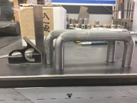
Here some detail photos of the inits. The pulse MIG really does a nice job eliminating unwanted spatter.
Thanks for looking.
Attachments


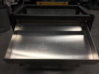
Couple of ongoing projects.
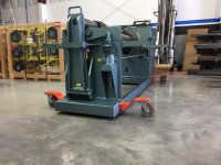
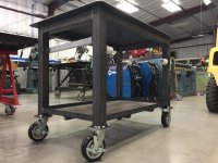
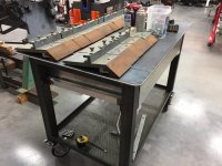
First one is a Lathe/mill support cart that can be used to transfer heavy chucks and larger tooling on to the mill. It also has a kneeling drawer to house 5C collets and metrology tooling.
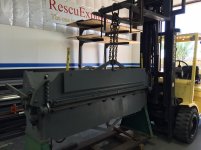
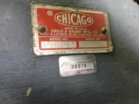
The second project is the rebuilding of a Chicago Dreis&Krump box&pan brake I purchased at auction. Its a 6' with 3",4",5" and 6" fingers built in 1977 and originally sold to the USAF. Second owners where the City of Gilbert AZ where they sold it on Public Surplus.
Having the extra space is nice for working on multiple projects including vehicle maintenance without tripping over stuff.
I will start with the lathe/mill cart.
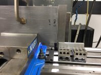
Main frame is made of .125"x2.5" square tubing 1/4"x 1.5" angle and 1/4" steel top plate. The rollers where made using precision bearings and deleon. The track is aluminum as is the drawer. A fair amount of machining has gone into this project and I build as I go without drawings.
I will have to post multiple times as I have too many pictures to share and limited to five photos per post. so here it goes.
First one is a Lathe/mill support cart that can be used to transfer heavy chucks and larger tooling on to the mill. It also has a kneeling drawer to house 5C collets and metrology tooling.
The second project is the rebuilding of a Chicago Dreis&Krump box&pan brake I purchased at auction. Its a 6' with 3",4",5" and 6" fingers built in 1977 and originally sold to the USAF. Second owners where the City of Gilbert AZ where they sold it on Public Surplus.
Having the extra space is nice for working on multiple projects including vehicle maintenance without tripping over stuff.
I will start with the lathe/mill cart.
Main frame is made of .125"x2.5" square tubing 1/4"x 1.5" angle and 1/4" steel top plate. The rollers where made using precision bearings and deleon. The track is aluminum as is the drawer. A fair amount of machining has gone into this project and I build as I go without drawings.
I will have to post multiple times as I have too many pictures to share and limited to five photos per post. so here it goes.
Attachments


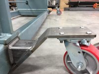
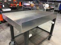
The base shelf is 14ga. perforated (scrap) supported by the angle grid and sits flat. I will use this area for less used tooling such as face plate,steady rest follow rest etc. The iron worker made short work of notching all the weld joints on the angle iron as well as castor flanges. The smaller rollers where turned and bored to take a press in bearings and glide between two opposing tracks. The hight if the top is 33" and the mill table can be lowered to match that height for vise transfer of heavier rotary table. The 1/4" top edges where bull nosed using a flap disc and the corners have a 1.5" radii.
Attachments


zmotorsports
ALLIANCE MEMBER
Beautiful work as always Paco.
Damn, that cart is **** as hell.
Damn, that cart is **** as hell.
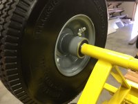
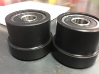
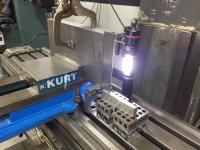
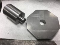
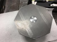
The front bottom rollers where done the same way as the smaller track rollers as far as bearings go but at a 3" finish diameter. Securing the large rollers required a hub made from left over 1.5" INVAR stock. Drilling the main frame to accommodate the hubs required a precise hole so I used the mag drill to accomplish this turning the frame on its side. I also used a clamp to back up the mag base as the material was only 2.5" and 1/8" thick. I used the 5C collet block to indicate the hubs on the mill and drill/tap the three holes 120º apart.
Then transferred them to the main frame securing with counter sunk Allen screws. The hub stick out was calculated to clear the upper tracks and end up with all four rollers shoulders in the same plane to capture the drawer. The drawer has not been built at this point.
Then transferred them to the main frame securing with counter sunk Allen screws. The hub stick out was calculated to clear the upper tracks and end up with all four rollers shoulders in the same plane to capture the drawer. The drawer has not been built at this point.
Attachments


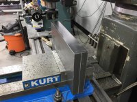
A 4x8 sheet of .100 aluminum was purchased and sheared per my calculations allowing for bending. It needed to fit the slot I had already made with the rollers so it was what I consider a critical measurement. I used a buddies B&P brake to fold up the sides. I was currently bidding on the B&P brake I now own and my apron brake was not up to the task for bending boxes. The aluminum tack is .560" above center line at the front to give me a 25º kneel when the drawer is out. A access hole was drilled on the rear track for assembly/disassembly.
At this point I realized the rear portion of the drawer needed a scab sheet to stiffen up the area that supports the rear rollers. A single piece was used with two 90º bends and married to the inside of the drawer and TIG welded inlace as wells the corners.
At this point I realized the rear portion of the drawer needed a scab sheet to stiffen up the area that supports the rear rollers. A single piece was used with two 90º bends and married to the inside of the drawer and TIG welded inlace as wells the corners.
Attachments


Next up was to design a 5C collet rack for my 65 piece set. I calculated all the hole locations for the 1.25" collet holes and standoff mounting holes on a sheet of paper to use on the mills DRO. The sheet used was cut using a jig saw and squared up on the mill on two sides. I mounted a bolster in the mills vise to provide a large surface to support the sheet. I failed to include the smaller roller hubs built the same way as the 3" hubs. These mount to the rear side of the drawer. They too are secured with counter sink Allen screws. I used some tools from my past aircraft days for counter sinking all aluminum.
To be continued.
To be continued.
Attachments

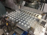


After drilling out 80 collet holes a quick pass using a de burring tool cleaned them right up. Then transferred the standoff hole to the drawer and mounted the rack.
The bottom screw holes are also flush. With 80 holes, it leaves me 15 extra for future specialty collets. The to bent sides (right and top) will block any items from rolling under the rack.
The bottom screw holes are also flush. With 80 holes, it leaves me 15 extra for future specialty collets. The to bent sides (right and top) will block any items from rolling under the rack.
Attachments


Next up was the drawer face. I had some 1/8" aluminum sheeting left over from a job so again I used a jig saw and ripped it length wise and cut the 3/4" radii on four corners.
Laid out on the protective film and mounted it using the same type of fasteners. For the drawer pulls, I wanted a beefy feel. I took some 5/8" CR round bar and cut to length. Drilled/tapped (1/4-20) both ends and knurled the center using a fine pattern. Lastly, I used the iron worker to break the 90º to complete the pulls/handles.
I still have a fair amount of work to complete this cart but holding off until my new lathe arrives. It should hit the shore in LA in early Jan and once it clears customs, I'll make to trip to bring her home. My current lathe weighs 2K pound (1440) and the new machine comes in at 3700 (1640) with a through spindle bore of 2-1/16". My Christmas gift from my wife. A lot of my current tooling for the tailstock is 3 m/t while the new machine is 4 m/t and the next phase of the cart build is a rack that will house all of that tooling as well as the QCTP goodies.
Thanks for looking.
Attachments


On to the Dreis&Krump brake.
I basically purchased this brake sight unseen with only four ****** photos on the auction web page for review. It all seemed to be there and I had little reservation with a max bid of $1500. These things fetch a fair amount used and new simply not feasible for me.
The 150 mile one way trip went well for the most part but the guy operating the fork lift had no idea how to pick this machine to load on to my tailer. Luckily I had with me a some rigging equipment and after having to talk him down he allowed me to rig it for loading. This equipment comes in at 3700#.
After spending several hours trying to adjust the folding apron and clamp within recommended tolerances, I realized all but on finger extensions where sprung/bent. Most of the nose bars are in excellant shape with only a few requiring resurfacing. I called Dreis& Krump and they still support this machine with parts and they where kind enough to email me a copy of the parts breakdown with P/N's. They want $21/inch for the nose bars so thats not happening. The extensions they sell are 3/4" hot rolled and they get a **** ton of money for those as well. The bushing they now sell are Oilite and they ask way too much for a complete set. I decided to tear apart the entire machine to check the pivot point tolerances. Most bushing have a max play of .001/1"diameter. I then realized why I could not get the adjustment I was after.
They where worn badly. Made up some tools on the lathe to pound out the pivot bushings/pins.
Attachments


Farmall450
Well-known member
Wow, nice shop OP. Also digging the Millermatic and the Hyster, both nice units!
For the finger extensions:
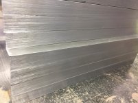
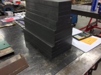
I sourced some 3/4" x 12" cold rolled flat bar six feet in length and used the Ellis 1800 band saw to cut the 3",4",5" and 6" widths. This was by far the largest piece of CR I have dealt with so far. The Ellis was to its max cut capacity as well.
Once the multiple fingers where cut, I used a shell mill to face cut them to proper dimension in pairs. Surprisingly, the saw set up yielded .001-.002" difference in 12" (flat cut) but they did have a slight taper to the cut of about .003" in 750". Still not bad considering the length of cut. The max hight on this saw is 9" so I could only cut it flat. Being cold rolled (CR) i was able to use the factory edge to set up the pairs square prior to face milling. The light came in handy to verify the set up. A machinist square was used along with a jack. The 2.5" shell cutter used was insert type TPG334 at 426RPM and 10 IPM power feed feed.
Attachments
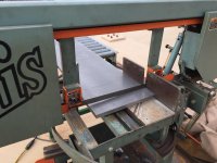
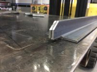
To cut the material to proper length of 10.5" with a 41º bevel the Ellis was used again. With the machined sides and to prosper width dimensions I was able to set up the pieces on edge.
I laid out the first one and set up a stop for the remaining 13 fingers.
The cut result was excellent with negligible variance if at all.
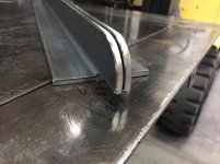
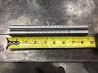
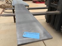
The green finger is original and the only survivor. I used this as a standard for the measurements for the new fingers. The last photo shows the 1.5" drops.
I laid out the first one and set up a stop for the remaining 13 fingers.
The cut result was excellent with negligible variance if at all.
The green finger is original and the only survivor. I used this as a standard for the measurements for the new fingers. The last photo shows the 1.5" drops.
Attachments


Wow, nice shop OP. Also digging the Millermatic and the Hyster, both nice units!
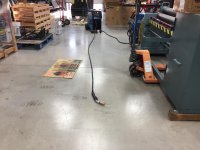
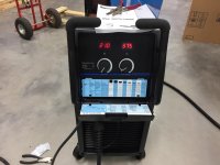
Thanks man, last October I added the Millermatic 252 to compliment the Miller 350P I use for heavier welding. The Hyster 50 has been a back saver as I work alone. I'm still waiting for the $300 rebate from miller for that 252

Next up was drilling/tapping (3/8-16) and counter boring the fingers. I used the DRO for all operations. The second and third photo shows the nose bar and clamp bracket in place. All the extensions still need the steps milled to complete them.
Waiting on a roughing end mill for those operations. I'm really stoked how the bevels turned out using a bandsaw. No machining required there.
Waiting on a roughing end mill for those operations. I'm really stoked how the bevels turned out using a bandsaw. No machining required there.
Attachments


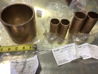
Took a break from the mill and hit the lathe after sourcing the bushing locally. They came out of Michigan and ran a total of 100.** including shipping. Dries& Krump wanted close to $400 plus $50 for shipping. Same Oilite ISO/SAE rating.
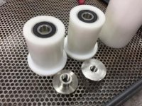
I could nor source the two 4" x 1.5" ring bushings but was able to purchase a 4"x5" single bushing I would make two from. This large bushing cost $45 while D&K wanted $76 ea.
I could nor source the two 4" x 1.5" ring bushings but was able to purchase a 4"x5" single bushing I would make two from. This large bushing cost $45 while D&K wanted $76 ea.
Attachments


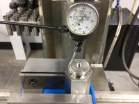
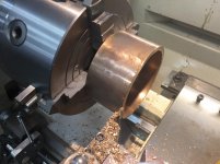
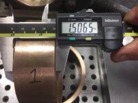
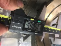
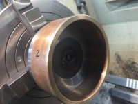
The large bushing was chucked in to the Bison 4 jaw combination scroll chuck and indicated within .0005. A groove was cut to provide a bevel matching the factory edge. A paring tool was then used slightly off center of grooves to preserve the bevel. This also allowed me to take a slight face cut to dimensions. Rinse and repeat for second ring bushing. The last photo (upside down sorry) shows the original bushing measurement (still installed) of 1.5065". Bushing #1 and #2 matched. Any closer and I be off
This stuff parted under cross feed at 300 RPM and dry as it's self lubricating.
Thats all for now on the brake project.
Turn and burn!
Paco
This stuff parted under cross feed at 300 RPM and dry as it's self lubricating.
Thats all for now on the brake project.
Turn and burn!
Paco
Attachments


Farmall450
Well-known member
Thanks man, last October I added the Millermatic 252 to compliment the Miller 350P I use for heavier welding. The Hyster 50 has been a back saver as I work alone. I'm still waiting for the $300 rebate from miller for that 252
The 252 is a sweet machine. I have an older 200 (still 230 amp) but I miss the digital controls of the newer units.
The 252 is a sweet machine. I have an older 200 (still 230 amp) but I miss the digital controls of the newer units.
My first machine was a millermatic 200 my wife bought me for Christmas of 87. That machine a 4"Makita grinder and a 14" Makita chop saw started my shop journey. That was a great machine and gave me 15 years of faithful service. I sold it for $800 to friend who still uses it part time. The digital readouts are nice as is the gun on demand feature when running a spool gun. The P350 is another animal all together and has handled everything I had thrown its way.
Lincoln makes fine machines these days for less money, but I'm true blue.
Lets just see about that rebate they promised me
Farmall450
Well-known member
My first machine was a millermatic 200 my wife bought me for Christmas of 87. That machine a 4"Makita grinder and a 14" Makita chop saw started my shop journey. That was a great machine and gave me 15 years of faithful service. I sold it for $800 to friend who still uses it part time. The digital readouts are nice as is the gun on demand feature when running a spool gun. The P350 is another animal all together and has handled everything I had thrown its way.
Lincoln makes fine machines these days for less money, but I'm true blue.
Lets just see about that rebate they promised me
Yeah, I'd like to invest in a spool gun. Haven't used one since high school.
I have a Lincoln tombstone, does that count???
Yeah, I'd like to invest in a spool gun. Haven't used one since high school.
I have a Lincoln tombstone, does that count???
Tombstone are tried and true. I learned to arc weld with one back in 78. Hard to beat a transformer machine. I'll let you in on a little secret, I own a Lincoln weld pac 100 110 mig loaded with 10# spool of flux core. I've owned this machine since 1992 and have ran countless 10# spools with it. Miles of wire without a hiccup so long as you have a good power supply. I think I have only replaced the contact tip once or twice. Its my go to for small outdoor yard repair.
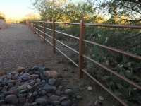
I fenced my entire property with this machine ( 2 days) but it was powered by a Miller bobcat 250. The nimble torch is great for stuff like this. The photo only shows one side of the property. It was over 800' in total. The first 110 mig I purchased was a Miller Cricket back in 89, that machine was a POS. The new Lincoln Power Migs are pretty darn nice.
Attachments
rmack898
Well-known member
Nice job on the brake Paco.
Just curious, if you have a 350P why you needed to get a 252?
I have a 251 and am planning to get a 350P in the near future and getting rid of the 251. Is there something that the 350P can't do that warrants the need for the 252 or do you just like having the redundancy?
Just curious, if you have a 350P why you needed to get a 252?
I have a 251 and am planning to get a 350P in the near future and getting rid of the 251. Is there something that the 350P can't do that warrants the need for the 252 or do you just like having the redundancy?
Nice job on the brake Paco.
Just curious, if you have a 350P why you needed to get a 252?
I have a 251 and am planning to get a 350P in the near future and getting rid of the 251. Is there something that the 350P can't do that warrants the need for the 252 or do you just like having the redundancy?
Thanks Mac,
The 252 purchase was based on a couple of things.
1) A backup machine (like you said) and to be used at the other end of the shop in the automotive bay (convenience).
2) A decent year in sales/income requires investing in the shop. With a career in Public safety and two other businesses, Uncle Sam always has his hand out for more. I don't mind greasing the wheel, but those fools find a way to screw the little guy. Seems the harder we work, the more we pay for the not so hard worker. Thats all I can say about this without getting political so I'll leave it at that.
You'll love the 350P, its a different animal in pulse mode.
Last edited:
Farmall450
Well-known member
That is one hell of a fence. Keep up the nice work!
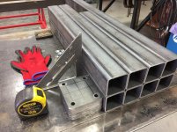
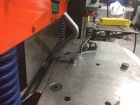
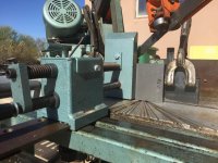
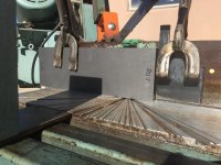
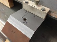
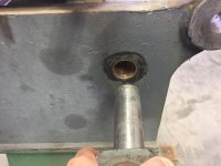
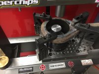
Made a tool to press out the 4" bushing on the link pivot on the B&P brake. I used a piece of .750" CR bar and cut a rough profile on the band saw staying close to the layout line. Drilled out the center to 7/8" using a annular cutter. Found a piece of 2" CR round in the scrap bin and turned the end to fit snuggly into the hole. welded the piece in and chucked it onto the lathe to turn the OD .150" smaller than the OD of the bushing to be pressed. Turned a shoulder to fit ID of bushing (.001 under). Used a condemned hydraulic cylinder to cut a sleeve that matched the profile of the link's OD and ID just large enough to pass the bushing through. Used the jig block to secure the whole enchilada and set it up on the press. Worked well.
Attachments


rmack898
Well-known member
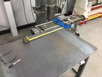
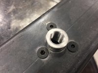
I like that jig block Paco, is that shop made?
What are the dimensions, hole spacing, and thread size? I might have to put making one of those at the top of my to do list for the new year.
What are the dimensions, hole spacing, and thread size? I might have to put making one of those at the top of my to do list for the new year.
zmotorsports
ALLIANCE MEMBER
I like that jig block Paco, is that shop made?
What are the dimensions, hole spacing, and thread size? I might have to put making one of those at the top of my to do list for the new year.
I was wondering the same thing. May have to machine me something like that as I don't like having holes in my welding table but could use a fixture plate like that many times.
I like that jig block Paco, is that shop made?
What are the dimensions, hole spacing, and thread size? I might have to put making one of those at the top of my to do list for the new year.
Hi Mac,
I purchased it on Ebay several years back when things where cheaper. I'm on shift today but will measure it tomorrow morning when I get home and post up the answers. I use it a lot on the pressing and layout. I gave under $20 for it (not including shipping).
Paco