To avoid these ads, REGISTER NOW!

Opening up a wall

SickSpeedMonte

Well-known member
Joined
Feb 28, 2017
Messages
81
Location
MD
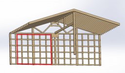
We just moved in to our new place and I started working on the shop. It started as a pole barn and had a garage added to the end of it where a sliding door was. The sliding door was removed and a wall was framed up. Both spaces were insulated and sheathed with corrugated steel. I want to create a pass-through for vehicles to get to the barn side. (There is another sliding door still on the other side of the barn that was also framed over to make the barn into a climate controlled gym, but no driveway and soft ground over there)

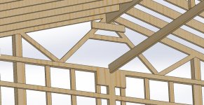
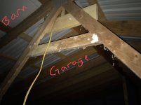
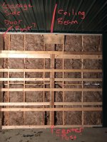
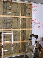
I found today that the barn side has trusses and the garage has rafters. The ridge beam for the garage is supported by the last truss. There is also a beam running directly below the ridge beam on the ceiling that supports it. Below that ceiling beam, there is a pieced together post of sorts made of two 2x6's. They are not continuous as one breaks at the girts and the other breaks at the fire break. I think it would have mad a lot more sense to put a 6x6 here instead, going all the way to the ridge. There are also a lot of girts on the garage (green) side. I'm curious if these were added to support that broken up center post. It seems like an afterthought.

The garage is deep, so if I can remove one of the original posts that I believe was for the sliding door, I could still have enough width to turn a car into the barn side. I would leave at least one wall stud beyond the central load-bearing post, as they are tied together with a short 2x12 at the top.

Am I missing anything? Any advice? Should I do anything to shore up that center post?
 

Attachments

  • EDE14DCF-F140-4AD4-9D64-249CA0C75085.jpg
    EDE14DCF-F140-4AD4-9D64-249CA0C75085.jpg
    92 KB · Views: 164
  • 57BAFABC-5D6B-4A2F-B386-89443008E478.jpg
    57BAFABC-5D6B-4A2F-B386-89443008E478.jpg
    118.9 KB · Views: 157
  • DD37957D-C1B3-4897-ABFF-C3DBC0D49C41.jpg
    DD37957D-C1B3-4897-ABFF-C3DBC0D49C41.jpg
    113 KB · Views: 163
  • 07CFC4F6-42BF-4E6C-81A6-F7DD7524BD64.jpg
    07CFC4F6-42BF-4E6C-81A6-F7DD7524BD64.jpg
    68.5 KB · Views: 154
  • 569BB67F-D5B4-4548-AB69-FE258F95F18F.jpg
    569BB67F-D5B4-4548-AB69-FE258F95F18F.jpg
    104.2 KB · Views: 159
  • 62F871C0-5785-4A8A-A7F1-30776C9E38EE.jpg
    62F871C0-5785-4A8A-A7F1-30776C9E38EE.jpg
    74.1 KB · Views: 159
To avoid these ads, REGISTER NOW!

fourbyford

Well-known member
Joined
Aug 3, 2017
Messages
913
Location
North Idaho... almost Canada!
...not sure I'm completely following either the description or pics but I do have a couple of comments.
1st, I would be concerned that the last truss on one side is supporting the ridge beam for the other side. Trusses are designed to support a required load (wind, snow) over a given span. To add an additional load from an adjacent roof, in my estimation, would clearly exceed the design specs for the original truss. This situation COULD be minimized with vertical support... or with SUBSTANTIAL reinforcement of the truss to resist shear forces. I, personally, would go with the vertical support. While it is more than likely you could open up a pass through between the two sides, care should be taken to support the ridge.
HTH
...D
 

Pluribus

Well-known member
Joined
Dec 16, 2012
Messages
2,143
Location
Skagit County, WA
^^What fourbyford said, and I'll add...

Not an engineer, but I'd be tempted to figure out how to support a big-*** header between what I think are the door posts you refer to, and get the load from the ridge beam transferred properly down to that instead of the truss carrying it.* You could also just drop a post straight down, if you don't mind an offset door, but then you'll end up with a much smaller opening with that and the existing posts.

Obviously this existing setup has worked for some time, but it's hokey AF, IMHO.

*"Correct" answer is to contact an engineer, but I don't think that's what you're asking.
 
OP
S

SickSpeedMonte

Well-known member
Joined
Feb 28, 2017
Messages
81
Location
MD
...not sure I'm completely following either the description or pics but I do have a couple of comments.
1st, I would be concerned that the last truss on one side is supporting the ridge beam for the other side. Trusses are designed to support a required load (wind, snow) over a given span. To add an additional load from an adjacent roof, in my estimation, would clearly exceed the design specs for the original truss. This situation COULD be minimized with vertical support... or with SUBSTANTIAL reinforcement of the truss to resist shear forces. I, personally, would go with the vertical support. While it is more than likely you could open up a pass through between the two sides, care should be taken to support the ridge.
HTH
...D

I agree with both if you on adding load to the truss that may exceed it's design load.

I'll try to model it so its clearer what's going on.

I think the opening could actually be a bit larger if I kept/added a real center post and removed one of the old 6x6's. The 16x8 roll-up door is to the right on the other side of the wall in this picture. All of the attic pictures in the OP were taken from the access hole circled.
 

Attachments

  • 444035F2-43EA-4ECD-B6A0-2284A1732C06.jpg
    444035F2-43EA-4ECD-B6A0-2284A1732C06.jpg
    155.9 KB · Views: 115
  • C1A399F0-996A-48E2-A90C-7686038A053F.jpg
    C1A399F0-996A-48E2-A90C-7686038A053F.jpg
    155 KB · Views: 149

fourbyford

Well-known member
Joined
Aug 3, 2017
Messages
913
Location
North Idaho... almost Canada!
Hey Speed,
Nice set up ya got there... I'm liking the floor!! Anyways, I'll expand a bit and agree with what Pluribus said...
To properly support the "framed" roof, you need to transfer the load from (both) ends of the ridge beam to the ground. In a perfect world, the most efficient way to do that would be to have a properly sized post (or column) extend from the bottom of the ridge beam (and securely attached to prevent twisting or shifting) to some sort of properly prepared base, footing, foundation or post hole... again, securely attached. When this is not possible, we go straight down, as far as possible, to an adequately sized header that is properly supported at each end with a post (or load bearing wall) that transfers the load to the prepared base. As long as you're keeping support under your loads (using adequately sized framing members) you should be fine to open up a doorway. One other thing you didn't mention... depending on how the roof is framed, collar ties are important. If you have a finished ceiling in that area, you're using them as ceiling joists... may not hurt to double check the method of attachment. If there's any doubt, as Pluribus mentioned, probably best to consult an engineer... or the dreaded building department.
Have fun, looks like you're going to have a great shop!
 

fourbyford

Well-known member
Joined
Aug 3, 2017
Messages
913
Location
North Idaho... almost Canada!
...just re-read your original post...
If it were mine, I would replace the cobbled up post with a pressure treated (rated for ground contact) 6x6 (at a minimum). The PO's cobbled up mess has obviously been standing, but add a heavy snow load and some wind and all bets are off! As I mentioned earlier, we want solid support under a load to transfer the load in as direct a route as possible all the way to the ground. You also mentioned a "beam" under the ridge beam... I would also check methods of attachment on that setup. It sounds as if, after installing the original ridge, they thought it was undersized and decided to beef it up... this may or may not work... depending on the sizing of the framing members and the method of attachment. This will go back to my comment about collar ties... if the ridge beam is not adequately sized, collar ties become critical to prevent the center of your framed walls from bowing out. And, while you're at it, I would double check how they supported the ridge beam at the far end. Might as well find all the questionable stuff and attack it now... once and done!
...D
 

mcclaar

Member
Joined
Mar 12, 2009
Messages
11
Location
Illinois
I'm looking to do something similar in the next year or two. I currently have a polebarn type garage that I want to add another stall and a half to.
 

fourbyford

Well-known member
Joined
Aug 3, 2017
Messages
913
Location
North Idaho... almost Canada!
...OK... one more go... I think I've finally had enough coffee and gotten most of the cob webs out... lol
If you replace the center post... from the ground all the way up to support the ridge beam UNINTERRUPTED (you may need to find a different way to attach the girts) you should be good to remove one (or both) of the "side posts". It appears those were there to frame the opening and, as long as the truss is intact, they do nothing to support a vertical load. Just curious... you refer to a ceiling beam... in one pic I see some sort of post extending from the ridge beam to the ceiling beam. Is there a post directly beneath that to transfer that load to the ground?? If not, something you may want (or need) to think about!
...D
 
OP
S

SickSpeedMonte

Well-known member
Joined
Feb 28, 2017
Messages
81
Location
MD
Thanks for the help (and compliments) everyone! You guys are awesome. There are no collar ties on the garage side, but there are ceiling joists connecting one wall to the other. Wouldn't that prevent the walls from bowing out?

The center post (4x4) going from the ridge beam to the ceiling beam beneath it is not supported below the ceiling. I'll try to get up there again today and get some pictures of the far side post supporting the other end of the ridge beam.

The garage was added on in 2016, so we could certainly have a larger snowfall than we have in the last 2-3 years. I'm not sure how I could support it solidly at the bottom though. The two older 6x6 posts should be set in the ground like the rest of the pole building posts.

Edit: those old door posts don't fall at an intersection in the truss. They are a little more inboard, but the drawings aren't dimensionally accurate.
 

Attachments

  • BarnGarageOpening.jpg
    BarnGarageOpening.jpg
    97.1 KB · Views: 46
  • GarageFramingClose.jpg
    GarageFramingClose.jpg
    136.4 KB · Views: 43
  • GarageFraming.jpg
    GarageFraming.jpg
    152 KB · Views: 42
  • BarnGarageFraming.jpg
    BarnGarageFraming.jpg
    92.8 KB · Views: 40
  • BarnGarageFraming2.jpg
    BarnGarageFraming2.jpg
    117 KB · Views: 47

fourbyford

Well-known member
Joined
Aug 3, 2017
Messages
913
Location
North Idaho... almost Canada!
Nice drawings... clears things up nicely!
-if the ceiling joists run, uninterrupted, from one side wall to the other and are properly attached to the wall/rafters, they will prevent the walls from bowing
-the concept of the "ceiling beam" (with the post from the ridge beam resting on it) COULD be valid... provided that the beam is substantial enough to carry the load. It's hard to know what that span is but, looking at your drawings, seems the ceiling beam is undersized. A heavy enough load at the center of the roof will try to deflect BOTH beams downward as it is built. This could be corrected by installing a post directly under the post coming from the ridge beam... and going directly into the ground. But, I'll guess you really dont want a post in the middle of your floor... so you could turn the two beams (ridge and ceiling) into a "truss" by adding web and gussets... think of the "W's" in a conventional roof truss. You would just be making a huge rectangular truss running down the center of your building. I wont go into extreme detail on that idea here... you can PM if interested...
-once you've supported the ridge beam, I cant see anything that would prevent you opening up the area you've indicated... should be a good project!
 
OP
S

SickSpeedMonte

Well-known member
Joined
Feb 28, 2017
Messages
81
Location
MD
I went back up today and the ceiling beam looks like a 2x12 and a 2x10. The weird part is it looks like a single piece of lumber with a notch cut out, rather than two separate pieces put together. I didn't see any fasteners holding two boards together or an obviuos joint. (Pic 1)

The post connecting the ridge beam to the ceiling was just a 2x4.

The 6x6 at the far end is not continuous. (Pics 2 and 3) It rests on top of the wall.

There are two more 6x6's on either side of it on that end wall. Those might be continuous. (Pic 4). They are not symmetric about the center post and dont seem to serve a purpose above the ceiling.

The ceiling rafters are 2x8's and are not continuous from wall to wall. They attatch to the ceiling beam with joist hangars. So it looks like I should have collar ties.

If I install a new post to replace the pieced together 2x6's that break at the girts and firebreak, how do I attach it at the floor? Do I need to cut a hole and poor a footer for it? Could I use a post bracket like on a deck?
 

Attachments

  • 42A0FCAB-036D-40D0-9BA3-26938A636BA1.jpg
    42A0FCAB-036D-40D0-9BA3-26938A636BA1.jpg
    96.4 KB · Views: 37
  • 1D5AE741-3B33-4D4F-8171-6E87DF973ED3.jpg
    1D5AE741-3B33-4D4F-8171-6E87DF973ED3.jpg
    53.2 KB · Views: 35
  • 9A8F8EC7-4A20-4A1A-A020-32BAAA045A7C.jpg
    9A8F8EC7-4A20-4A1A-A020-32BAAA045A7C.jpg
    96.4 KB · Views: 32
  • 7D7AA5CB-7D62-4109-B8F0-0CA94D2457AA.jpg
    7D7AA5CB-7D62-4109-B8F0-0CA94D2457AA.jpg
    56.9 KB · Views: 33
Last edited:

fourbyford

Well-known member
Joined
Aug 3, 2017
Messages
913
Location
North Idaho... almost Canada!
...well... where to start...
I'll offer some advice that is my take on what I'm seeing through some pics and my understanding of the situation. Also, when I'm building, I tend to take the "belt and suspenders" approach... I don't like surprises...
From the pics, i honestly dont know what has kept this end of your building standing... i think if you would've had a severe winter (like we get out here) you may be looking at a collapsed roof. I think your situation is urgent...
-as far as how to attach the load bearing 6 x 6 that you will replace... the "business" end of it needs to rest on undisturbed (or compacted) ground. It's hard to say what's underneath your slab. You MAY be able to get by with using a post bracket, which might keep it from shifting side to side... but, keep in mind, this post is supporting a ridge beam that is carrying a significant load from the roof above. If the soil under your slab was never properly prepared, a heavy snow load on the roof could exert enough force on the concrete to fracture it and cause your roof to sag. The issue here is that this building is somewhat a hybrid... part post framed and part conventional framed. In this instance, if the building were mine, I would cut through the floor enough to dig a post hole deep enough to get below frost line (although in the center of a conditioned space, that may or may not be an issue... I would do it anyway)... compact the bottom of the hole and either pour it full of concrete (as a pier) or set the post and concrete it in. The problem on that end is solved. Cut your door opening and call it a day.
The other end, however, is another story. From the pics, it looks as if they notched a 6 by and set the ridge beam into it (at least I hope it's set in), then, my guess is that the lower end is attached to a girt or is resting on something that's not capable of carrying the roof load. As mentioned in above posts, our goal is to support the load of the roof through substantial framing members all the way onto a foundation or footing. If the post that supports the ridge on that end does not go all the way to the foundation, it should be resting on a header adequately sized to carry the roof load over the span between the vertical posts extending into the ground. The simplest solution would be to install a 6 x 6 post from a post hole (as before) to the ridge. If that is not possible, a header supported by the existing 6 bys with the "ridge post" properly attached should suffice. Keep in mind... with all these connections, gussets will be required to prevent framing members from shifting.
Finally, I don't know that you need to replace your ceiling joists... we just need to ensure that they solidly tie the end of a given rafter to the end of the opposing rafter to prevent the walls bowing out. You may be able to develop a plywood gusset that would span the ceiling beam and tie the ends of the ceiling joists together... or maybe a metal tie plate tieing the ends of the joists to the beam from the underside.
I realize that my observations are not the best news you could've gotten (sorry) but, better to identify and correct problems before they might result in damage or injury.
Let me know if I can be of any further help... if I was closer, I'd come for a short visit and we'd git r' dun...
Be sure to post progress... and pics!!
...D
 
To avoid these ads, REGISTER NOW!
OP
S

SickSpeedMonte

Well-known member
Joined
Feb 28, 2017
Messages
81
Location
MD
I need to take off the panel on the end wall and see what's in there. I'm so tired of finding surprises with this place... the house was a whole other ball of wax.

I am setting this shop up for metal work. I have a CNC plasma table that I built from scratch. Maybe the first project will be some brackets that tie one ceiling rafter to the other. The rub is there is blown-in insulation up there, so pulling the ceiling metal down will be a big job. I'd rather do collar ties and the truss idea between the ridge and ceiling beams.

I'm going to pull down more interior wall panels and see what's going on.
 

fourbyford

Well-known member
Joined
Aug 3, 2017
Messages
913
Location
North Idaho... almost Canada!
...just thinking... if you do the center "truss" idea (of tieing the ridge and ceiling beams together) the collar ties become less of an issue and your existing ceiling joists would probably be adequate (although I'd still look at their connection to the beam).
 
OP
S

SickSpeedMonte

Well-known member
Joined
Feb 28, 2017
Messages
81
Location
MD
I appreciate you taking the time to help me think through all of this.

I'll figure out what to do about the free-standing end once I open up the wall over there.

As for the connection to the barn, I'm hesitant to do any ground work right now. It's done nothing but rain for 6 months here (record shattering rain fall numbers last year, this year isn't looking much better so far) and our ground is completely saturated. Our property has a creek running through the back of it and some more drainage work needs to be done to help the area around the shop. We had to dig a couple of 2-3' deep holes to repair a sump line and they filled in with water right up to the surface overnight. I can't imagine concrete curing properly in those conditions.

I'm wondering if I would be better off using the existing 6x6 posts and putting a header over them to support the ceiling/ridge beams. The truss between the two beams would give the shear stiffness along the axis of the ridge. This might not be advisable as the 6x6's are on the inside of the last truss and the ridge beam starts on the outside.

I did find a local engineer that will do a site visit for ~$400...
 

fourbyford

Well-known member
Joined
Aug 3, 2017
Messages
913
Location
North Idaho... almost Canada!
I had briefly considered ways to maybe stiffen the last truss to be able to support the load. One thing I thought of was to "skin" the truss with plywood... glued and nailed possibly on both sides which would essentially turn it into a solid element and significantly increase its strength. Maybe a combination of that and using the existing 6 bys could solve the problem... ditto for the other end. I'm still rather concerned with the length of the ridge with questionable collar support. I think the $400 would be money well spent to get an engineer out there to assess the building and make a recommendation. You can make him aware of the concerns and I'm sure he'll come up with solutions.
I'm definitely with you as far as the conditions you're dealing with. I'm continually trying to improve the buildings around our place (we've been here a bit less than 6 years)... hardly a day goes by that I dont find some little "surprise" left by a previous owner. And, each spring, we deal with ground water issues as well. The first year I was here, my post holes turned into water wells. Oh well, a good problem to have, I guess.
Hey, it's cool that you built your own plaz setup. That's something I've considered... I have the fabrication and machining skills but I'm pretty clueless as far as logic circuits are concerned. Are you using lead screws driven by stepper motors? How are you controlling them? Which software?
Anyways... glad i can be of some help with your issue. I feel like I'm at a bit of a disadvantage cause I'm a couple thousand miles away and cant crawl around the building to check things out. My buddy (from back "home") and I always say that it helps to just have someone to bounce ideas off of... I think that's my primary role here... you got this!!
Keep us posted!
...D
 

kbs2244

Well-known member
Joined
Nov 11, 2006
Messages
14,065
I think you owe fourbyford a few breakfast tacos for that review of your problem.

The key thing is the change from truss to ridge beam construction and the need for centered support.

If you can accept an off center door everything will be easier.
 
OP
S

SickSpeedMonte

Well-known member
Joined
Feb 28, 2017
Messages
81
Location
MD
Lol breakfast tacos. I do owe him a beer, or at least some help with a plasma table when the time comes.

I built my chassis to this design
https://www.instructables.com/id/CNC-Plasma-Table/

It runs pulleys. With a jet cutter, you don't really need the torque from a screw drive, but you want speed. Especially for thinner material that you have to cut faster. That's not to say that you can't do it with screw drives, and you'd probably have less backlash. This is a little cheaper I guess. It runs V-groove bearings on 2X2 box tube turned diagonally. One day I will use this one to build another one, and I will probably make a 4X8 or even a 5X10. I'll use linear bearings next time and something beefier for the drive. Maybe ball screws, maybe just bigger pulleys/belts. This works, but if you want to do really fine detail, the backlash could be better. I run two X-axis steppers and one Y, all big (3 Nm?) NEMA 23's. Overkill, I'm sure, but the price wasn't much different. The Z-axis is a smaller stepper, I forget off the top of my head what it is, and that is a screw drive with awl thread and a captured, floating nut.

It's actually controlled by an Arduino Uno with USB into my laptop. I liked being able to CAD in the old house, make the CAM files, and then go out into the garage, plug the laptop in and burn. There's no tower that has to stay in the shop and get files transferred onto it. I have a GRBL shield (another board with pins that fits directly onto the UNO), and originally had 8825 drivers. Drivers take step pulses and a direction (high/low) signal and a DC power input to run the motors with current that can't go through the control board.

The Uno is running GRBL firmware, which is mostly used for printers and some routers. The 8825 motor drivers connected right to the shield, but weren't skookum enough for my giant NEMA 23's (should have known just by looking at them... but the spec's checked out). I swapped them out to TB6600's and stopped loosing steps/overheating drivers.

The tricky part with using 3D printer firmware was the Z-axis. With a plasma, the Z-axis has to be both open-loop and closed-loop, depending on the situation. The X and Y axes are both open-loop full-time. Printers, routers, mills, are all open-loop, meaning you put in a command and the machine does it with no feedback to modify the toolpath. The Z-axis on a plasma is controlled with feedback from the arc voltage while cutting to maintain a set arc length. So my controller sends Z steps and Z direction signals through relays. The relays are controlled by the coolant pin on the Uno. Normally, the steps/dir are passed from the Uno through the relays to the drivers. That allows the CNC (Uno) to control the Z for clearance moves during rapids, and to probe the material before each pierce. The Z axis hardware floats on bearings. The CNC drives it down into the workpiece until it touches and keeps going until a limit switch opens. Then it sets the Z height to some negative number (whatever it takes to go from touching the work to opening that switch). Then it can go to pierce height, start the arc, lead-in and drive down to cut height. At that point, the "coolant" is turned on, switching control of the Z-axis driver to a Proma torch height controller (THC). The Proma gets a divided arc voltage from my Powermax 45XP power unit and adjusts the Z axis height to maintain that arc voltage to the target voltage, within a tolerance. With the THC, if the bed isn't 100% parallel to the axes, or the work warps from the heat, you still maintain the desired arc height for a clean cut.

It would probably be easier to use an old tower with a printer port running Mach CNC software, rather than the Uno/GRBL route. It's been done, for plasma, a million times so you don't have to figure this stuff out on your own. The printer/serial port also runs at a higher signal voltage than USB, which increases your signal to noise ratio and makes interference less of an issue. I had to shield/ground all of my cabling and drive a separate ground rod just for the table to ground the EMI.

I got a lot of my hardware on ebay, waiting 3 weeks for orders from China. Order spares, it's saved me a few times. I figure all-in, I probably have $1,500 in the table. The plasma was $2,200 with a machine torch. I spent a few hundred more to have a hand torch too. They can be very easily swapped on the Powermax. I had the laptop. For CAD, you can download Draftsight 2D for free. Inkscape is another free program that can create .dxf (vector files) that can be used to cut. It's more of a graphic design program, so its good for anything decorative like signs. For CAM, I spent $120 on SheetCAM, and it was money well spent. The CAM program takes your CAD file and turns it into a toolpath. You can get a free trial version that just limits how many lines of G-code it will make. There is a text file called a Post-Processor that takes that toolpath and turns it into G-code, which is what the CNC controller reads. SheetCAM comes with maybe 40-50 post-processors which are set up for different CNC controllers (such as Mach or GRBL). The post-processor can be customized, which is how I tell the controller when to turn on the "coolant" to trade control of the Z-axis, and how to probe the material.

I'm probably rambling now... if you get into building one, you'll have questions. I'll do my best to help you out if you need it!
 
Last edited:

fourbyford

Well-known member
Joined
Aug 3, 2017
Messages
913
Location
North Idaho... almost Canada!
Hey... thanks for the detailed info! I need to download this post for future reference. I am familiar with CAD/CAM software... and G Code. In a former life I was a machinist in an R&D shop and did a bit of production work... CNC turning center and machining centers and a LOT of one-off manual work. Haven't done a lot with plaz tho. Something I could definitely use these days!
Hope you're able to resolve the issues with your shop... I know how aggravating and disruptive it can be... having something like that hanging over your head. I've been plugging away at a shop project... wiring, installing permanent air lines (inside the walls) insulation and osb to cover the walls. The job itself is issue enough but we've finally gotten some winter here... cold, snow, more cold, even more snow... and just everyday life sometimes slows my progress to a crawl. I just want to get this phase wrapped up so I can get back to the other ten (pressing) things on the list! lol
Be sure to let me know how the visit with the engineer goes!
...D
 
OP
S

SickSpeedMonte

Well-known member
Joined
Feb 28, 2017
Messages
81
Location
MD
Ah, cool. You'll pick it up quickly. It's not as complicated as it seems.

It sure is disruptive. I still own my old house (unfortunately), but the good news is I still have my shop set up there. I was hoping to open up this wall, run some circuits, and bring my equipment over. I do fabrication on the side, and I would really like to get this shop useable. I haven't even been able to make it out to look at the other wall since the weekend... had to disassemble our oven last night to replace the insulation because the PO's mouse policy was open-border, and then finished up the pantry for the missus.
 

fourbyford

Well-known member
Joined
Aug 3, 2017
Messages
913
Location
North Idaho... almost Canada!
Wow! ...your life sounds a lot like mine!! Hmmm... what was it Red Green said... If the women don't find ya handsome, they should at least find ya handy!
That's definitely my motto!!!
...D
 
OP
S

SickSpeedMonte

Well-known member
Joined
Feb 28, 2017
Messages
81
Location
MD
Funny, I just saw Red Green on my youtube recommended videos yesterday. They're watching...

I don't know why it didn't dawn on me sooner, but my mentor at work mentioned years ago that he designed a building for our organization once... and he's a PE/PhD engineer. He came over yesterday and took a look. Good news is, it's not going to be too difficult to remedy the situation.

The 2X12 ridge beam is an LVL, 24' span. The ceiling beam is another 2x12 LVL and a 2x9.5" LVL run parallel. I ran the snow load numbers this morning and calculated the material weights. I need to figure out how to tell what the spec is on the LVLs, but it's possible that the ridge and ceiling beams are properly spec'd. I counted 13-14 plies on each beam.

https://www.bc.com/content/uploads/2018/09/E-spec-guide-BCI-and-VL.pdf (Page 28)
I used 30 psf ground snow load (I'm in the 25 psf zone but close to the border), Ce 1.0 (exposure factor), Ct 1.2 (temperature factor for unheated), Is 1.0 (importance factor), and came up with 25.2 psf for my sloped roof. Then calculated material weights for the roofing/ceiling metal and joists. I calculated 11,650 lb total on the beams, not counting the weight of the beams themselves. 24 ft span. So that's a sum of 485 lb/linear foot.

To support the beams at the divider wall, he said to get another 2x12 LVL and hang it between the 6x6 posts above the ceiling and then support the truss and ridge beam with it. That's a 10' span, so the LVL is plenty. Another just below the ceiling to support the ceiling beam, and then I could have a clear span between the 6x6 posts.
 
Last edited:

fourbyford

Well-known member
Joined
Aug 3, 2017
Messages
913
Location
North Idaho... almost Canada!
Awesome news! Sounds as if you'll be able to get your building functional (and the doorway you want) with a minimal outlay of time/money/materials... and the HUGE peace of mind of knowing that all is well. Was nice of your co-worker to come out and look things over!
Be sure to post up some pics of your project!
...D
 
To avoid these ads, REGISTER NOW!
Top Bottom