To avoid these ads, REGISTER NOW!

Outlet wiring question

To avoid these ads, REGISTER NOW!

wyliesdiesels

Well-known member
Joined
Aug 14, 2012
Messages
19,994
Location
Modesto, CA
No other breaker in that box or the well house. The wires on the upper left side of the box (with yellow wire nuts) go to the outlets.

Yes, I'll post a pic of the main panel interior tomorrow.

So then they hooked up the wires from both circuits to the 30a breaker?

Looks like #12 which is a code violation.

This needs to be fixed.
 

AntonLargiader

Well-known member
Joined
Nov 20, 2016
Messages
1,372
Location
Charlottesville, VA
The feed from the house to the outlets is one thing. As already said, it could be on a 30A breaker which is wrong. But as for why the receps aren't working right, I would just replace them and you can verify the wiring as you do so. The one you show looks like it has gotten water or something else in past the cover. IMO it's WAY better to use a GFCI breaker (rather than GFCI receps) for outdoor circuits, so maybe you can power that circuit from a GFCI breaker in your main panel. That would fix both problems at once.
 

teamextreme

Well-known member
Joined
Aug 10, 2013
Messages
867
Location
Lakewood, CO
You have another feed from the house serving the outlets.

Winner. There is a black and white #12 that come into the panel with the #10 feed wires for the pump that just splice in the box and go out to feed the outlets. So there is likely another breaker in your main panel feeding just the outlets. Trace that feed conduit back to the main and see where the #12 black and white wires go. My guess is another breaker. None of this helps as to why the outlets are not working correctly, but it's a start to figure out how they're fed.
 
OP
L

L5wolvesf

Well-known member
Joined
Dec 4, 2011
Messages
1,831
Location
Northern AZ
Re the attached pics.

The main panel is the one with my finger pointing to the 2 pole well house breaker. There is a pic of the conduit that leads out toward the well house.

There looks to be a lot more wires going into the exit conduit on the right than what comes out in the well house. That is likely because the RV space circuit goes out that general direction too – but not in a straight line with the well house. If a diagram would help to 'see' that layout let me know.

The RV space has the 1 round receptacle and the smaller box below that is a GFCI outlet. It is the 30 amp breaker in the main panel just below the well breaker – it is in the off position.

The breaker to the RV space is always off when the RV is not occupied. I haven’t had it on for a couple years now. I don’t see, or know, that it has any direct connection to the well house.
 

Attachments

  • Main panel Well breakers.jpg
    Main panel Well breakers.jpg
    62.2 KB · Views: 68
  • Main panel wire exit.jpg
    Main panel wire exit.jpg
    94.4 KB · Views: 64
  • RV outlets.jpg
    RV outlets.jpg
    132 KB · Views: 58

mike93lx

ALLIANCE MEMBER
Joined
Dec 9, 2013
Messages
37,422
Location
Richmond, VA
IMO, this sounds like it is above your skill level for electrical work.

I think you need to bring in a pro to evaluate.
 

wyliesdiesels

Well-known member
Joined
Aug 14, 2012
Messages
19,994
Location
Modesto, CA
Ok so you have 2 sets of conductors going into the well house but only one breaker(30amp) feeding it and there isnt 2 hots on one pole of the 30a breaker so we dont know how the outlet circuit gets power.

At this point you need to trace the black and white wires for the outlet circuit.

Does it come into the main panel at the same place as the pump wires? Theres too many wires to be able to tell just looking at pics.
 
OP
L

L5wolvesf

Well-known member
Joined
Dec 4, 2011
Messages
1,831
Location
Northern AZ
People are going to get tired of looking at too-close-up pics that don't show what's really going on.

On the main panel pics I figured the pics needed to be up close so the wires could be seen as clearly as possible. On the RV receptacles pic I can't back up any further, the RV is there.
 
OP
L

L5wolvesf

Well-known member
Joined
Dec 4, 2011
Messages
1,831
Location
Northern AZ
IMO, this sounds like it is above your skill level for electrical work.

I think you need to bring in a pro to evaluate.

If it is beyond rewiring the outlets yes. But I would like to know what to tell a pro may be wrong with it. Currently, the pump works and so do the outlets.
 
OP
L

L5wolvesf

Well-known member
Joined
Dec 4, 2011
Messages
1,831
Location
Northern AZ
Ok so you have 2 sets of conductors going into the well house but only one breaker(30amp) feeding it and there isnt 2 hots on one pole of the 30a breaker so we dont know how the outlet circuit gets power.

At this point you need to trace the black and white wires for the outlet circuit.

Does it come into the main panel at the same place as the pump wires? Theres too many wires to be able to tell just looking at pics.

I'll see what I can figure out at the main panel with that mess of wires. I tried to move them a bit but it is packed pretty tight. And it is almost as messy as the well breaker box.
 
OP
L

L5wolvesf

Well-known member
Joined
Dec 4, 2011
Messages
1,831
Location
Northern AZ
Winner. There is a black and white #12 that come into the panel with the #10 feed wires for the pump that just splice in the box and go out to feed the outlets. So there is likely another breaker in your main panel feeding just the outlets. Trace that feed conduit back to the main and see where the #12 black and white wires go. My guess is another breaker. None of this helps as to why the outlets are not working correctly, but it's a start to figure out how they're fed.

I'll see if I can find it if there is one.
 

checkthisout

Well-known member
Joined
Sep 5, 2008
Messages
5,232
Your tester is faulty.

What issue were you having that made you test them in the first place?
 

teamextreme

Well-known member
Joined
Aug 10, 2013
Messages
867
Location
Lakewood, CO
If the well house outlets "work", then start shutting off breakers until they shut off, that will tell you how they're fed.
 
OP
L

L5wolvesf

Well-known member
Joined
Dec 4, 2011
Messages
1,831
Location
Northern AZ
If the well house outlets "work", then start shutting off breakers until they shut off, that will tell you how they're fed.


this. and see if they are on the same/different circuit from the pump
one you've identified circuits it will probably be easier for people to help you diagnose

There is one unlabeled breaker in the main box that may be it.
 
OP
L

L5wolvesf

Well-known member
Joined
Dec 4, 2011
Messages
1,831
Location
Northern AZ
Found the breaker that feeds to the well house outlets – it is in the main panel. It is an unmarked 20 amp single pole. It started raining again so I didn’t open the panel.

Does this tell you anything good or bad or about the original question about the outlets which was . . .
On 2 outlets the tester reads “open hot” (but they work), on 1 outlet the tester’s first light is red, no others are on.
 
To avoid these ads, REGISTER NOW!

LS6 Tommy

Well-known member
Joined
Dec 27, 2013
Messages
26,162
Location
Northern NJ
There's a lot of "WOW" in those pics. I'd get a decent electrician in there pretty quick.

Tommy
 
Last edited:
OP
L

L5wolvesf

Well-known member
Joined
Dec 4, 2011
Messages
1,831
Location
Northern AZ
Test voltage at the outlet from hot to neutral, hot to grnd and neutral to grnd

Will do Thank you. I have an ‘I’m not an electrician’ question on the test procedure. Should I pull out the outlet and test where the wires attach or test via the plug side?
and
Should I do all 3 outlets AND the light or??
 
OP
L

L5wolvesf

Well-known member
Joined
Dec 4, 2011
Messages
1,831
Location
Northern AZ
There's a lot of "WOW" in those pics. I'd get a decent electrician in there pretty quick.

Tommy

Yeah it is sloppy. If the fix for the outlets is a simple rewire I'll tackle the box clean up myself. I was around for a similar situation elsewhere.
 

ard

Well-known member
Joined
Feb 16, 2015
Messages
4,391
Location
Sierra Foothills... California
you could plug a light into any of the receptacles in the shed.

Turn off 15 or 20A breakers until the light goes off. THAT will tell you which breaker supplies that 120V black wire out to the shed.
 
OP
L

L5wolvesf

Well-known member
Joined
Dec 4, 2011
Messages
1,831
Location
Northern AZ
based on that, you need to open all boxes and fix a miswired neutral. Likely at box #2


There should NEVER be potential between neutral and ground.

So now you know whats wrong just have to find the cause...

#2 was the one with an odd reading on my tester and one I can not recall ever using. I will check it out tomorrow. Thank you.
 
OP
L

L5wolvesf

Well-known member
Joined
Dec 4, 2011
Messages
1,831
Location
Northern AZ
The feed from the house to the outlets is one thing. As already said, it could be on a 30A breaker which is wrong. But as for why the receps aren't working right, I would just replace them and you can verify the wiring as you do so. The one you show looks like it has gotten water or something else in past the cover. IMO it's WAY better to use a GFCI breaker (rather than GFCI receps) for outdoor circuits, so maybe you can power that circuit from a GFCI breaker in your main panel. That would fix both problems at once.

I checked out the #2 outlet yesterday and the black and white wires are in the wrong places on at least one side of the outlet.

Before I get to rewiring I have a couple questions.
1. As suggested above would it be better to have a GFCI breaker for this circuit; 3 exterior outlets (1 is a GFCI but I will be removing it) and 1 light. That sounds correct, I just want to verify?

2. If I do change the breaker to a GFCI is using the GFCI outlet I mentioned on the inside a good or bad idea?

Thank you for the help so far.
 
OP
L

L5wolvesf

Well-known member
Joined
Dec 4, 2011
Messages
1,831
Location
Northern AZ
After some delays due to weather, work and other things I finally got back to this. I did some of the cleanup of the wiring for the outlet circuit (put the wire coming out of the subpanel in conduit, rerouted it and eliminated an unnecessary outlet).

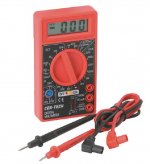
I then wired in a GFCI outlet as the first one in the circuit (as previously suggested). To verify it was wired correctly I plugged in my tester and got an “open hot” reading. I tested with the meter and the reading between the ground and hot side is still reading 121 volts. Since the outlet was an old one I put on a new one (not GFCI) – the meter was still reading 121 volts between the ground and hot side. Thinking it could be something on one of the outlets down line I took the wiring down line off – still the same.

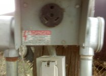
So I still have a problem, but different than before. Previously the outlet in that box read first light red no others lit (no idea what that means) – now it reads as “open hot”. The voltage readings are the same as before – 121 volts between the ground and hot side of the outlet. So, the way I see it now is the problem has to be somewhere in the subpanel in the well house and/or the main panel. I wired the line from the subpanel to the outlet the same as it was before; white to white, black to black, and ground to the ground bar (close up of ground bar attached).

The question is what are the possible causes for the ground getting 121 volts?
One thing I noticed when stripping back insulation was the clear layer of insulation over the colored (black or white) has become deteriorated (like it had been in the AZ sun) and detached from the wire. My questions on that are:
1) Is this “normal” (the wire is likely from the late 90s and none of the wire has been exposed to sun?
2) Is the colored (black or white) insulation sufficient to insulate the wires?

Your help is appreciated.
 

Attachments

  • Well Breaker box ground bar.jpg
    Well Breaker box ground bar.jpg
    118.5 KB · Views: 32

mike93lx

ALLIANCE MEMBER
Joined
Dec 9, 2013
Messages
37,422
Location
Richmond, VA
I am confused. You will always see power between hot and ground on a live circuit.

The neutral and ground are connected at the main panel....
 
OP
L

L5wolvesf

Well-known member
Joined
Dec 4, 2011
Messages
1,831
Location
Northern AZ
I am confused. You will always see power between hot and ground on a live circuit.

The neutral and ground are connected at the main panel....

Actually you just un-confused me. The outlets down the line were originally wired wrong via the first outlet. So now it is correct. But, why does the tester read "open hot".
 

wyliesdiesels

Well-known member
Joined
Aug 14, 2012
Messages
19,994
Location
Modesto, CA
Hot to ground SHOULD read 120v

Do you have a multi-meter?

Test neutral to ground. Should be 0v

then test Hot to neutral. should be 120v

Have you tried the tester on a known good outlet?
 
OP
L

L5wolvesf

Well-known member
Joined
Dec 4, 2011
Messages
1,831
Location
Northern AZ
Hot to ground SHOULD read 120v

Do you have a multi-meter? Yes

Test neutral to ground. Should be 0v

then test Hot to neutral. should be 120v

Have you tried the tester on a known good outlet?

Since these outlets worked I thought all of them here were good. I'll check it.

I'll retest things tomorrow. Thank you
 
To avoid these ads, REGISTER NOW!
Top Bottom