To avoid these ads, REGISTER NOW!

Overseas Jack Rebuild Help Tutorial.

OP
H

Hiball

Well-known member
Joined
Apr 30, 2009
Messages
14,026
Location
Missery
Hi Hiball,

I have one of these older jacks and I am having difficulty lowering my jack. The release gear attached to the handle is not sitting flush inside the gear attached to the jack and is just spinning freely without engaging the other gear. Is there anyway to reposition one of the gears so they are sitting flush inside one another?
If memory serves, the upper gear/stem sits in a hole (bottom) and most are held in place with a cotter key. I’m assuming you haven’t removed the lower release gear and didn’t get it seated deep enough upon reassembly and that’s causing the issue?
 
Last edited:
To avoid these ads, REGISTER NOW!

oreo9

Member
Joined
Sep 12, 2022
Messages
6
If memory serves, the upper gear/stem sits in a hole (bottom) and most are held in place with a cotter key. I’m assuming you haven’t removed the lower release gear and didn’t get it seated deep enough upon reassembly and that’s causing the issue?
Thanks for your reply @Hiball. I have never disassembled the jack nor did my father when he was alive (it was his jack and it passed down to me). I am not sure if he got the jack new or used, but am 100% positive he never disassembled it. I definitely would have remembered that. So are you saying I need to reseat the gear? And if so, is it the upper gear or lower gear in the photo I shared?
 
OP
H

Hiball

Well-known member
Joined
Apr 30, 2009
Messages
14,026
Location
Missery
Thanks for your reply @Hiball. I have never disassembled the jack nor did my father when he was alive (it was his jack and it passed down to me). I am not sure if he got the jack new or used, but am 100% positive he never disassembled it. I definitely would have remembered that. So are you saying I need to reseat the gear? And if so, is it the upper gear or lower gear in the photo I shared?
It’s hard to tell how far the two gears are off, when you lower the handle can you get the gears to mesh up by simply turning the handle one way or the other? If you follow the upper gear down, you find that the bottom stem protrudes thru the bottom of the handle assemble and is secured with either a cotter pin or I’ve even seen some that have a nut. It prevents the assembly from riding up too high. EBE810A0-0BD9-4ABC-B7D2-652E15D5CE68.jpeg
 

oreo9

Member
Joined
Sep 12, 2022
Messages
6
It’s hard to tell how far the two gears are off, when you lower the handle can you get the gears to mesh up by simply turning the handle one way or the other? If you follow the upper gear down, you find that the bottom stem protrudes thru the bottom of the handle assemble and is secured with either a cotter pin or I’ve even seen some that have a nut. It prevents the assembly from riding up too high. EBE810A0-0BD9-4ABC-B7D2-652E15D5CE68.jpeg
So I thought the gear you circled was the gear with the cotter pin as the other gear looks bolted/screwed to the base of the floor jack.

In the image I shared, the bar was in the upright position and sitting all the way down flush on the square nut that you have to tighten/loosen to raise/lower the jack when you turn the handle. When I took the photo, I turned the bar both clockwise/counterclockwise and the gear you circled turned fine both clockwise/counterclockwise, but the bottom gear that you didn’t circle did not turn as the top gear was not making contact with it. This is when the bar is in the upright position. When I lower the bar and turn the handle, the two gears seem to come slightly closer together, but not enough to turn the bottom gear. I thought though, most people lower the jack when the handle is in the full upright position like in my image. Is that not true?
 

oreo9

Member
Joined
Sep 12, 2022
Messages
6
I gave a Chinese jack to a friend years ago that the gears no longer meshed. I didn't need it anymore & never looked a the problem. he managed to fix it, don't remember what he did .
Good to know there is a way to fix it. Now I just need to figure out how.
 
OP
H

Hiball

Well-known member
Joined
Apr 30, 2009
Messages
14,026
Location
Missery
So I thought the gear you circled was the gear with the cotter pin as the other gear looks bolted/screwed to the base of the floor jack.

In the image I shared, the bar was in the upright position and sitting all the way down flush on the square nut that you have to tighten/loosen to raise/lower the jack when you turn the handle. When I took the photo, I turned the bar both clockwise/counterclockwise and the gear you circled turned fine both clockwise/counterclockwise, but the bottom gear that you didn’t circle did not turn as the top gear was not making contact with it. This is when the bar is in the upright position. When I lower the bar and turn the handle, the two gears seem to come slightly closer together, but not enough to turn the bottom gear. I thought though, most people lower the jack when the handle is in the full upright position like in my image. Is that not true?
When you have the handle in the upright position, It’s common for gear mesh to be off a bit and hard to operate, but the handle should operate both gears. The majority of time you are operating the release the handle will be in the operating range of the actual pump piston. IF you follow that upper gear/stem down, you need to make sure the stem is secured thru the lower assembly. It also appears that the handle assembly is missing the bolt to secure the handle, with the handle pinned it also keeps the stem/gear secured.
 
Last edited:

oreo9

Member
Joined
Sep 12, 2022
Messages
6
When you have the handle in the upright position, It’s common for gear mesh to be off a bit and hard to operate. The majority of time you are operating the release the handle will be in the operating range of the actual pump piston. IF you follow that upper gear/stem down, you need to make sure the stem is secured thru the lower assembly. It also appears that the handle assembly is missing the bolt to secure the handle, with the handle pinned it also keeps the stem/gear secured.
I think you are right because the handle comes out of the lower assembly easily. If I bring the handle down to be in the range of the pump piston I have to be extra cautious not to accidently pull the handle out of the lower assembly otherwise the lower assembly will snap back up to the upright position. If the jack is in far underneath the car with lower assembly only slightly sticking out from under the car, I have found it hard to get the handle back into the lower assembly as it is in the upright position and when I try to get the handle in, it hitting the front or side of the car depending on where I placed the jack. I don’t think my dad got the jack new then because that bolt to secure the handle was never there when he got it.
 

oreo9

Member
Joined
Sep 12, 2022
Messages
6
I think you are right because the handle comes out of the lower assembly easily. If I bring the handle down to be in the range of the pump piston I have to be extra cautious not to accidently pull the handle out of the lower assembly otherwise the lower assembly will snap back up to the upright position. If the jack is in far underneath the car with lower assembly only slightly sticking out from under the car, I have found it hard to get the handle back into the lower assembly as it is in the upright position and when I try to get the handle in, it hitting the front or side of the car depending on where I placed the jack. I don’t think my dad got the jack new then because that bolt to secure the handle was never there when he got it.
So I found this video on YouTube where the guy in the video has the exact same problem as me. A couple of guys commented in the comments section to tighten the bolts on the side of the jack. I will try that on the weekend and see if that fixes it.
 
OP
H

Hiball

Well-known member
Joined
Apr 30, 2009
Messages
14,026
Location
Missery
So I found this video on YouTube where the guy in the video has the exact same problem as me. A couple of guys commented in the comments section to tighten the bolts on the side of the jack. I will try that on the weekend and see if that fixes it.
We aren’t talking about a lot of moving parts/adjustments that affect how the gears line up. It should be fairly obvious, but making sure that upper gear and most importantly the bottom stem is seated and secured is a easy check.
 

sdowney717

Well-known member
Joined
Mar 17, 2010
Messages
964
The speed side is pretty simple, What you are looking for is a setting (seat pressure) that allows the lift arm to raise and hold its own weight/return spring pressure.

1. Make sure the jack has sufficient oil and he been bled.

2. With the lift arm down, Not under load, turn the handle clockwise to full stop and operate the jack. You are looking for the lift arm to raise substantially. If you don’t get the quick lift feature you need to increase seat pressure by tightening the adjustment clockwise, Reset the lift arm and work in 1/4 turns till the lift arm rises and doesn’t fall under its own weight. It’s best to start light and work your way up.

If you overtighten the valve, you stand a chance of damaging the components and rupturing the quick lift tube, too light and it will suffer performance wise.
I may have just busted whatever tube you are mentioning on the Speedy Lift floor jack I have.
Jack was jerking up with handle till hit the load. Then it was very hard to lift the load up, lots of force on handle to lift car. Hande was like bending under the pressure.
Then when i backed it down, it refused to drop after tire hit the floor. Then it went to raise jack again and some big POP sound and the jack was working real well, lifted car without bending the handle down almost effortless. But now no speedy lift at all. Works like a non speedy jack.

Can you tell me how to replace that speedy lift tube?
The jack has always been jerky on the speedy lift and a pain to use. Like with jack just sitting there, push handle down and front wheels lift off the ground. I oly looked at using it again when the other floor jack broke.

But now works decently.

I took off the cylinder and painted it and took out each valve, everything inside looked clean. I do think it may have been low before on oil.
Refilled with power steering fluid.

Here it is, and what model is the jack? IT has an MVP pump
And which adjustable valve is the one for speedy lift?
1678989591518.png

1678989650645.png

1678989693390.png


1678989729215.png
 

sdowney717

Well-known member
Joined
Mar 17, 2010
Messages
964
Shinn Fu filed the patent for 'speedy lift' in 1998
Found this patent was filed in Taiwan.
Here it is and it shows how it works, there is a central tube that runs up inside the main ram. What happens is the handle plunger piston and the ram tube diameter are close to the same size, a move of the handle plunger piston down also displays about the same oil up the little tube, thus lifting the ram a lot.
I think that tube popped on my jack.
I think it popped the tube as the valves were not set to transfer the handle plunger piston pressure to the main ram.

It is maybe a threaded tube, might be repairable. Later this summer I might open it up and see, depends how busy I get. It may also be thick walled. Right now the Jack tries to do a speedy lift when all the way down.

I uploaded the Shinn Fu PDF on the speedy lift.

Patent here, google does not show it
Taiwan patent office shows the drawings for 431443 patent

1679340004245.png

1679340235119.png
 

Attachments

  • TB000430807_GN__1_087211660_431443.pdf
    673.5 KB · Views: 11

sdowney717

Well-known member
Joined
Mar 17, 2010
Messages
964
I translated the chinese patent text using Chinese OCR to text set to simplified chinese, then took the chinese text to english using deepl translator.
I also translated using google translate
So here are some text files.
One text file was set to traditional chinese.
They are all differ a little. But you can sort of understand the patent, how the jack works.

websites used
OCR to text
deepl translator
google translate

You kind of hope for better translation, but It may be impossible without a bilingual person looking at it.
 

Attachments

  • Using simplified chinese from web s.txt
    31.5 KB · Views: 3
  • translated.txt
    30.8 KB · Views: 7
  • deepl translation.txt
    33.7 KB · Views: 6
OP
H

Hiball

Well-known member
Joined
Apr 30, 2009
Messages
14,026
Location
Missery
It’s not that complicated of a system, there are probably 50+ threads here at GJ showing the inner workings of the single pump/quick lift jacks. If your tube is ruptured, it can be replaced with a donor, I just don’t know how much effort I would personally put into it.
 

sdowney717

Well-known member
Joined
Mar 17, 2010
Messages
964
It’s not that complicated of a system, there are probably 50+ threads here at GJ showing the inner workings of the single pump/quick lift jacks. If your tube is ruptured, it can be replaced with a donor, I just don’t know how much effort I would personally put into it.
I put in whatever effort is needed when I feel like it.
It actually works as it is. Just no speedy lift.
I also think the over load is the one on the far right and the speedy lift setting is right to the left of the relief valve (down valve)
I noticed that ball guide had wear, and none of the others did.
So it was bypassing the pressure a lot there, which makes me think it is the speed jack pressure setting.

For me, jack might sit there a few days, a few months or a few years.
Does tube thread in to the base?
It is metric sized?
When they rupture, do they split as in form a crack along the tube or do they just snap off?
I was thinking I could silver braze it and smooth it again. I have no donor parts.
 
OP
H

Hiball

Well-known member
Joined
Apr 30, 2009
Messages
14,026
Location
Missery
I honestly don’t work on them enough to remember what side is what, I can tell by looking at the components of the valve. The tube doesn’t thread into the base, if memory serves it held in place by a washer/orings that is secured by cylinder threading into the block. The tubes that I’ve seen that are ruptured (here) also show it blown out at the tip, normally followed by difficulty retracting the jack etc, Without tearing it down, it’s all speculations. It’s not a bad system, but to work properly, it requires the correct setting, a good main ram seal that can pull enough vacuum to fill the cylinder when the quick tube does it’s job.
 

sdowney717

Well-known member
Joined
Mar 17, 2010
Messages
964
Maybe it just blew some oring. Jack does not hang up going up or down it is smooth. I am using it right now, it works good.

I was thinking the shiny worn look on the ball guide must be the load sense valve for the speedy lift as it will be bypassed every stroke of the handle when under a load, where it then sends the oil flow pressure to the main ram cylinder, you would think then it will be subject to more wear. that adjustment valve is right next to the control valve (immediate left) for dropping the jack down.

The other far away valve all by itself shows no wear. Like it never opens much, made me thing that is max weight overload.
If I ever take it apart, I can trace the oil flow path, then I will know for sure.

Both those valves have the same sized spring, and that spring is strong.
The valve next to the drop valve has a cap screw cover then an adjustment screw for spring pressure.
The other far valve, far right, (max load set valve?), has no cap, the screw is its own cover.

And since I picked the jack up from down the street years ago as it was being thrown out, I have no idea if anyone did anything with these valves.
 
Last edited:

Dinosaw

New member
Joined
Mar 24, 2023
Messages
4
Location
Charlottesville, VA
Well after numerous requests ive decided to put together a tutorial that will assist you do it yourselfers resurect/maintain your Taiwan Jack. This tutorial will cover the Main version of these jacks and i will try to include any variances that you might encounter. Again your jack might be different in color or possible fastener type but it will share the same hydraulic system along with location of key componenets for your typical Overseas 2-3 ton floor jack, This doesnt include Quick Lift Jacks as they will be a tad bit different and include another valve system. If you have any questions feel free to contact me with a Picture and I will assist you. Enjoy GJ and Have a Happy Holidays.

DSC00947.JPGDSC00948.JPGDSC00949.JPG

This is your typical Overseas design that i had sitting in the back of the shop, I had cabbaged the rear casters off this jack and it was a perfect candidate for this write up.

Well to start off you will need to remove the handle assembly, I used a impact to speed up the process.

DSC00950.JPG

Once both upper bolts are removed you can remove the Handle assembly and the handle return spring, On some jacks you will have 2 of these, 1 on each side. This particular model only has 1.

DSC00954.JPGDSC00955.JPG


Handle assembly Gone.


Next you will remove the lower bolts, these are fastened by a 3/8 allen head so you can get to them without removing the wheels. While you are here you will notice the silver bar at the rear of the jack this is just a stiffening brace held on by nuts that protrude thru the frame, this needs to come out.


Once you remove all bolts you can pick up on the rear of the frame and slide it forward, This will expose the next step.


Using a Prybar or Screwdriver slip the return spring off, On some jacks there will be 2 of these, This one has only 1.

Using a Cotter Key remover tool or side cutters Pull the key out.

We are now ready to head over to the vise.

Once secured in the Vise you can pull the Pump straight out, There will be no seals on it as they are inside Jack.


This particular style uses a flat recessed seat that uses a ball to seal the unit, There are different models and yours might have a Needle valve instead of this one. If thats the case there wont be a small ball as indicated by the next Pic. Remove the ball and keep it seperate.


Next step is to take the working valve apart, This particular model uses a allen head, Most use standard screwdriver Head.


After removing the socket head you will need a small pen magnet to remove the inner workings. This particular model uses 2 balls, the biggest ball on top and the smaller ball in the bottom seat. (keep these ball seperate from other parts) There will also be other styles in different models etc, Some will use spacers in between the balls and even springs can be found etc. Regardless keep track of how things come apart and in which order and you will be good.


The next valve to the right of the release is your overload valve, i cant tell you how many jacks ive had brought in that the only thing that was wrong was this valve had backed itself off and wouldnt let the jack lift the apropriate tonnage. Anyways First you must take the Dust cover off, Sometimes it will have a warning "DO NOT ADJUST" sticker on it. As you can see there is another Standard Screwdriver Socket inside the Valve, Using a small enough screwdriver so that you dont muck in the internal threads up. IMPORTANT****** First count the revolutions it takes to tighten the inside set screw completely down, On this particular jack it took 6. That is too many and as i stated earlier these do back off over time. If your jack was working fine except for leaking write down how many revolutions it took and upon reinstallation set it back to factory settings. If you dont remember or fail to head this warning 2 full turns back from full set is a good starting point. The overload is very important and is designed to keep you from overloading the jack and possibly rupturing a seal. This is why it is important you follow the tonnage guidlines and DO NOT crank this down all the way. There is NO way to set this Properly without having a Test station.


This is the workings of a typical overload, You will have a small ball that sits in the seat, A Upper seat with a *** to sit inside the heavy spring, Then top piece and as you can guess the *** goes down inside the spring and set screw tightens down on top of the flat. Sometimes theses are tricky to reinstall so here is a hint: Insert the small ball verifying that its is in the seat, Grab some wheel bearing grease or a heavy grease, Dab a little on the tip, insert into the spring and do the same for the top piece then drop as 1 piece down int the valve. Ive seen people get that first piece in there sideways and then when you crank the set screw down it damages things. Take your time and visually check what your doing.


Next you will need a Pipe Wrench or the apropriate Socket to remove the Tank nut. Keeping a pan handy to catch the oil.


Once you unthread the Tank nut the pressure will be released from the resevoir and you dissasemble.


And here we are at Paydirt, We finally got to the Ram Cup to verify what version we have. This particular version is the Oring sitting inside the Hollow Cup shell. It by far is the Most common found in 95% of your newer jacks and is Not the Best designed sealing surface, but it is Cheap.


Verify that there is no internal Damage, The jack was full of oil so there wasnt any Rust or Pitting. Looks Good:thumbup:

Ok now that we have the jack apart lets get working on removing the seals, 1st off lets remove the Orings on the Pump. Using a small Pic (I prefer the Snap on angle) Dig the Orings out being carefull not to damage the Backups, As they can probably be re-used. This particular jack has 2 Oring grooves machined inside, Some only have 1. If you have 2 the order of the Oring/backup is ORING on bottom in each groove and beveled side down Backup on top of the Oring. Lost? Keep Following?


Its hard to determine by these pics but this is a backup, Its not broken its split to allow easier installation. A back up has a flat side and a beveled side to allow the oring to sit inside and keep it properly shaped under pressure.

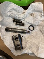
This Picture shows everything that came out of the Pump side.

Next seal is the Tank Nut seal, Using a Pic Remove this and set aside.
Hiball,
Really appreciate this writeup. I have a Craftsman 2 ton 214.12400 jack that has traveled to most of the race tracks that I ran back in the 80's and 90's with my vintage Mustang. Rebuilding it is sort of a personal project. The only 2 pieces I can't find are the slotted backup o rings for the pump. Do you know of a source for this pieces? They look OK in the pump, but I want to replace the o rings. Any tip for removing them without damaging the backups.
 

sdowney717

Well-known member
Joined
Mar 17, 2010
Messages
964
I honestly don’t work on them enough to remember what side is what, I can tell by looking at the components of the valve. The tube doesn’t thread into the base, if memory serves it held in place by a washer/orings that is secured by cylinder threading into the block. The tubes that I’ve seen that are ruptured (here) also show it blown out at the tip, normally followed by difficulty retracting the jack etc, Without tearing it down, it’s all speculations. It’s not a bad system, but to work properly, it requires the correct setting, a good main ram seal that can pull enough vacuum to fill the cylinder when the quick tube does it’s job.
I think the main ram seal must be good, it does not leak down. AND this, I can lift the front saddle of the jack up and it stays up, like it fills cylinder with oil. That is one way to set the jack higher before you start pumping the handle, which I have done a couple times lifting the car and it then lifted the car fine.
 
To avoid these ads, REGISTER NOW!
OP
H

Hiball

Well-known member
Joined
Apr 30, 2009
Messages
14,026
Location
Missery
Hiball,
Really appreciate this writeup. I have a Craftsman 2 ton 214.12400 jack that has traveled to most of the race tracks that I ran back in the 80's and 90's with my vintage Mustang. Rebuilding it is sort of a personal project. The only 2 pieces I can't find are the slotted backup o rings for the pump. Do you know of a source for this pieces? They look OK in the pump, but I want to replace the o rings. Any tip for removing them without damaging the backups.
Are you talking about the split type backups that mate to the Oring?
 
OP
H

Hiball

Well-known member
Joined
Apr 30, 2009
Messages
14,026
Location
Missery
That's the piece I need. Through the jacket is labeled as a 214.12400 it looks more like the 214.12000 I see in some of the parts diagraphs.
Thanks, B

In all honesty, they offer No sealing properties, the split style is easier to install versus the one piece BN. I’d reuse them if they aren’t damaged, just pay attention to the orientation, Once side is flat, the other concave to accept the Oring and keep it from distorting under load, thus they are directional.
 

sdowney717

Well-known member
Joined
Mar 17, 2010
Messages
964
I resused that kind of seal before. If it is not leaking or worn out. They made or make millions of jacks like that.
 

Superdavey

Active member
Joined
Apr 23, 2016
Messages
44
Location
Canada
In all honesty, they offer No sealing properties, the split style is easier to install versus the one piece BN. I’d reuse them if they aren’t damaged, just pay attention to the orientation, Once side is flat, the other concave to accept the Oring and keep it from distorting under load, thus they are directional.
By "BN" are you referring to Buna-N backup rings?

I recently rebuilt a Blackhawk B76411 that had a badly damaged backup ring on the pump piston housing. I wasn't able to source the original style of backup ring that I guess is made from teflon? The best I could find was a "Buna-N" backup ring. Its definitely a lot softer than the original one however it seems to hold up. I've been able to lift my F150 with the jack and no issues so far.

Is it okay to use the softer "Buna-N" backups on these jacks?

I also had hissing sounds coming from the jack when pumping under load ( I think I probably damaged the valve seats after I tried to clean the bores with a powered wire brush). Thanks to you guys, I ended up following the lapping guide from the other thread and epoxied the check balls to hollow aluminum rods I picked up from Amazon. Used the purple valve grinding compound that was water based to lap the valve seats. I ended up doing all all of the seats while I was at it ( I think my problem was the safety valve check ball not seating properly). I put new balls and tapped them in gently. The jack works great now ... No hissing or any other issues what so ever now.

I have the tension on the safety valve screw at 1 and a half turns from bottomed out. It was set at 2 turns however it seems pretty weak for a 2 ton at 2 turns... won't get my pickup truck off the ground at that setting. Turn and a half can get my pick up lifted with no issues. Is it possible I have it set too much at turn and a half for this jack?
 
OP
H

Hiball

Well-known member
Joined
Apr 30, 2009
Messages
14,026
Location
Missery
@Superdavey Yes, the BN backup is fine as long as it’s the right size to mate to the Oring.

It’s Impossible to say whether or not the Overload is set correctly without a test station. If the jack previously could lift your truck and after the rebuild it struggled, I’d say you are OK. The job of the overload is to prevent cylinder pressure from exceeding seal capacities. It’s possible that when you lapped the seats you increased depth and that’s why your original setting failed to allow you to lift the truck. I don’t believe your are in any danger of your jack failing because of a 1/2 turn extra, just remember Jacks are for lifting, Jack stands for supporting.
 

1964Fastback

New member
Joined
Jun 28, 2023
Messages
3
Hey All! New member - wow, great thread on hydraulic jacks.

I'm rebuilding my old Hollywood Accessories 649N 2 ton floor jack from the late '70s/early '80s. I'd like to thank 4xdog for uploading the manual and sticker jpg. I converted the manual to a pdf to make it easier to print out and use while I work on the jack. I'll try to upload it here.

I think I've got the o-rings covered, but was wondering if someone had a source for a couple of other parts. I need what's called the screen washer for the bottom of the pump piston chamber, #63 in the parts diagram. I measure it at .721" OD. Looks a little like an aerator for a faucet.

screen_washer.jpg

The other thing is the cup seal for the pump piston, #75. Measurements are .472" OD, .229" ID, .272" height.

cup_seal.jpg

I've tried the local hydraulic suppliers and they didn't have either of those. One place was at least able to help with some of the other o-rings.

There's one other screen washer, #82 at the bottom of the ram cylinder. I haven't bothered to unscrew the ram cylinder yet to get measurements until I figure out if these screen washer things are even available.

Thanks!

Pat
 

Attachments

  • hollywood_accessories_floor_jack_649N_manual.pdf
    2.8 MB · Views: 10

1964Fastback

New member
Joined
Jun 28, 2023
Messages
3
Update on the rebuild of my Hollywood Accessories 649N 2 ton floor jack above.

Here's the part numbers and sources for the parts I used:

#55 & #56 - Replaced both with MU25X35X10 from Hydraulic Parts Supply, Sawyer KS
#75 - HW 69407 cup 11.9 mm from HPS above

#43 - 314MMB70 Metric Buna o-ring 31 x 4 mm from oringsandmore.com, Henrico VA, 804-741-1521
#73 - 63MMB70 Metric Buna o-ring 6 x 3 mm also from oringsandmore.com

#61 - This is the o-ring that fits in the pump cylinder housing and wipes the pump piston. I measured this as 12 mm ID and 2.5 mm cross section but this was too big. It would not fit in the groove in the housing. I happened to have an o-ring that did fit, that I picked up locally, but unfortunately I don't have the measurements.

#63 - I couldn't find any screen washers this size. I replaced it without the screen, using a 7/16" copper washer from Harbor Freight assortment 67526. The washer measures about .707" OD and .482" ID. I annealed this to red with a propane torch.

I also couldn't find a big screen washer for the bottom of the ram cylinder, #82 in the drawing, so I didn't bother taking the ram cylinder out and just flushed it good with brake cleaner. And I reused the two giant fiber washers, #81, at the ends of the oil chamber. Thankfully no leaks around either of these.

Finally, I initially reused the rubber sleeve-type seal around the release valve. The drawing seems to show an o-ring for this, but that's not how my jack was built:

IMG_20230623_091348.jpg

Anyway, the original seal weeped some. I read elsewhere that someone used vacuum line to make a new one, and that's what I did. I had various vacuum lines laying around. I found some that had an OD that I could just work down past the threads in the jack, and that made the ID a tight fit over the end of the release valve. I don't know the size, though. Apparently it's the one piece of line on the planet that doesn't have the manufacturer's name and size printed all along it.

Anyway, hopefully this information will help the next person working on this model jack!

Pat
 
Last edited:

Arne73

Well-known member
Joined
Mar 20, 2010
Messages
1,477
What oil are you guys using after a rebuild?
I have 2 jacks on the bench and that's kinda holding me up.
I have plenty of transmission fluid (dexron 3 and up) as well as hydraulic fluid.
 

1964Fastback

New member
Joined
Jun 28, 2023
Messages
3
I'm not an expert so I just went to Autozone and picked up a quart of Fram Hydraulic Jack Oil. I'm sure there are other things that will work, are cheaper, etc. but I didn't want to over think it. Someone would have a hard time convincing me my choice was "wrong" though.

Pat
 

Arne73

Well-known member
Joined
Mar 20, 2010
Messages
1,477
I'm not an expert so I just went to Autozone and picked up a quart of Fram Hydraulic Jack Oil. I'm sure there are other things that will work, are cheaper, etc. but I didn't want to over think it. Someone would have a hard time convincing me my choice was "wrong" though.

Pat
Pat-
Sounds like a good choice to me. I'd like to thin out my accumulated oil if possible.
 

wwk68

Well-known member
Joined
Mar 18, 2021
Messages
52
Location
Midwest
I've got a 3 ton Central Hydraulics floor jack losing height when under load. Exact same design as others on this thread.

Looking for a rebuild kit, but this is the only thing that I find on Lazzar's website:


They do have a full seal kit for the 2 & 3/4 ton ($50 bucks). Would this work for the 3 ton?


Anyone know of a cheaper alternative kit?
 

paulsomlo

Well-known member
Joined
Jul 16, 2013
Messages
3,852
Location
Northern Colorado
I've got a 3 ton Central Hydraulics floor jack losing height when under load. Exact same design as others on this thread.

Looking for a rebuild kit, but this is the only thing that I find on Lazzar's website:


They do have a full seal kit for the 2 & 3/4 ton ($50 bucks). Would this work for the 3 ton?


Anyone know of a cheaper alternative kit?
Try Hydraulic Parts Supply in Sawyer KS, Phone: (620) 594-2247
 

Option01

New member
Joined
Apr 5, 2024
Messages
1
Hello, I've got an old 649N floor jack that was my dad's. It recently started weeping oil out of the seam around the piston so I took the piston out and found that its cup seal was mostly missing (see in pic below). I found a seal kit for sale online so it shouldn't be a problem to put a new seal on there but I assume I need to get the remains of the old seal out of the piston port? If so, can anyone here advise me on how I can might be able to do that? Any help would be greatly appreciated.

Here is a link to the manual if that helps:
 

Attachments

  • IMG_4670.jpg
    IMG_4670.jpg
    1.1 MB · Views: 19
  • IMG_4671.jpg
    IMG_4671.jpg
    847.1 KB · Views: 19

Dinosaw

New member
Joined
Mar 24, 2023
Messages
4
Location
Charlottesville, VA
Finally got back to my jack rebuild project. I am still having issues after the rebuild. It's a Sears 2 ton Model 214.12400 from 1987. I replaced the O-ring on the hydraulic cylinder tube nut, the pair of pump shaft O-rings and backers, the sealing ring on the working value (small ball is first, the large ball on top. The Main ram seal Ucup seal was in great shape, so I left it in place.

I bench pumped the unit after filling and bleeding. With no pressure, the ram pumped out slowly, so I thought I was good to go. Reassembled the jack and the unit will not pump out the ram. Note, if I close the release valve an pull the lifting assembly up, the unit will support my weight (around 240), doesn't bleed down and there are no apparent leaks.

Any tips on what I may have done wrong and how I might get this unit working would be appreciated.
 

jlabelrecord

Member
Joined
Jan 7, 2025
Messages
11
It’s been a day since I’ve bought valve balls due to the large quantities they come in, but they are friendly with magnets so I’d rule out SS but definitely Polished. I can’t say I’ve ever needed to replace the washer under release mechanism, so can’t help you there. Did you lose it? Its not vital pressure point for the jack as the ball/seat holds the pressure till it lifts and then the pressure is guided towards the reservoir. I have on occasion have needed to add a Oring that matches the OD of the washer if I notice any seepage at the threads.
Not sure if this is still going but, I do get seepage through my threads on the relief valve nut on my Allied Hydraulic HDJ2-10 2 ton jack. I also noticed some coming out through the center post which I think I'd need a new o-ring? And at this moment my jack won't go back down after taking everything apart and cleaning. My release valve has a round coupler with a square in the middle. The "square" that goes into that washer is attached to the release valve. Am I supposed to have that all the way tightened up?
 

jlabelrecord

Member
Joined
Jan 7, 2025
Messages
11
Finally got around to test the jack on the project car.
Frist issue, as soon as it had just a little weight, oil started pouring out of the check valve screw. It stops after some major tightening, I don't remember it being that tight coming off.
Then it would just lift take the weight off the spring but would not lift the car. I started making 1/2 turns till I could raise the wheel. I made 1 and 1/2 turns. I only backed it off 2 turns, does that sound right.

All in all, it did raise the wheels, so it was strong enough to raise the driver side of a GP. I let sit there all day and it held. So I feel pretty good about it.
Did not see any leaks.

iBAoMO3Iq1hurmx-4D1SLgHFA=w1160-h880-no?authuser=0.jpg
Were you ever able to get the leak to stop? I have the same issue coming from the threads as well as on top of the gear! When putting your release valve back in, did you have the pin all the way tightend to the valve or leave it a little loose? Thanks!
 
OP
H

Hiball

Well-known member
Joined
Apr 30, 2009
Messages
14,026
Location
Missery
Not sure if this is still going but, I do get seepage through my threads on the relief valve nut on my Allied Hydraulic HDJ2-10 2 ton jack. I also noticed some coming out through the center post which I think I'd need a new o-ring? And at this moment my jack won't go back down after taking everything apart and cleaning. My release valve has a round coupler with a square in the middle. The "square" that goes into that washer is attached to the release valve. Am I supposed to have that all the way tightened up?
The washer needs to be seated in place by the Release threaded portion, if not, it will just simply spin and not allow the release stem to lower and raise when the gear is rotated. The most common issue people have when reinstalling the release assembly is that the stem bottoms out before the release assembly is seated. In order to properly seat the assembly, start with stem in height that will allow you thread the assembly in, all while keeping the square shank inside the washer. Once it bottoms out, rotate the gear to raise stem, while also rotating the assembly to till it’s completely seated.
 
To avoid these ads, REGISTER NOW!
Top Bottom