To avoid these ads, REGISTER NOW!

Power to Detached Garage / Shop

bronc076

Well-known member
Joined
Jul 17, 2023
Messages
190
Location
Ozarks
Some background information:

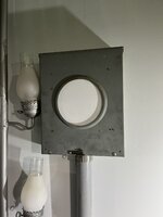
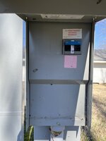
When our house was built back in the 1970s the electric meter was on the back of the house, the electric panel is located on the other side of the wall in the garage. Previous owners enclosed the porch so now the house has a "sun room." A couple years ago the electric company removed the meter from the sun room and placed it on a pedestal near the transformer which is in my neighbor's back yard. All cabling in my neighborhood is burried. This pedestal similar to the one linked below, it has a 200 Amp breaker to provide over-current protection. The power company moved the meter because the system for reading the meters was not working since it was now inside. The electrician removed the guts from the old meter socket, spliced the wires together, taped them up and screwed the lid on with a blank in the meter hole.

similar pedestal

I'm having a detached garage/shop built. I need to run power to the new building which will be approximately 10 feet from the sun room so probably no more than 50 feet total. My existing panel is pretty crowded and I don't want to fish big wires through it and install a big breaker. Lots of wires.

We do not have any type of electrical inspections where I live but I want to do this safely.

I'd like to remove the old meter socket in the sun room and install a "Terminal Box" (splitter box, bussed trough, I'm not sure what to call it) similar to the one linked below. This will feed two panels. So essentially I'll have two main panels, one in the house, and one in the shop. There will be no other metallic connections between the two buildings, no plumbing, gas lines, etc. The panel in the shop will have a UFER ground attached to rebar in the footer.

Is anything about this unsafe?

terminal box

or

Attached is a picture of what's going on in the sun room right now.

Can any of you recommend a terminal box that will handle the 2/0 AL wires. That's what's run underground even though it should be larger for a 200A service i'm sure we never draw anything close to 200 amps, probably not even a hundred.

Thanks
Rob
 

Attachments

  • IMG_5973.jpg
    IMG_5973.jpg
    564 KB · Views: 60
  • IMG_5974.jpg
    IMG_5974.jpg
    567.8 KB · Views: 59
To avoid these ads, REGISTER NOW!

dave*99

Well-known member
Joined
May 5, 2009
Messages
4,274
Location
Coastal NJ
The 200A breaker in the new pedestal is the first disconnect. You would need a 4 wire connection from that point to the panels in the new garage and the house to meet current codes. They should be subpanels with no bond between neutral and ground.

Consider running 4 wires feeders from the pedestal to the panels.
 

wyliesdiesels

Well-known member
Joined
Aug 14, 2012
Messages
20,067
Location
Modesto, CA
When they moved the meter to the pedestal and put in the 200a disconnect they didnt convert the main to a subpanel and 4-wire like they should have if it was just a few years ago unless youre on a pre-2008 code cycle

So as said above you need 4-wire from the disconnect not the old meter pan since its only 3-wire…

Also, if the main in the house doesnt have a disconnect thats another no-no…
 
OP
B

bronc076

Well-known member
Joined
Jul 17, 2023
Messages
190
Location
Ozarks
Yes I realize this is a code violation, the power company probably should have installed a new run, or billed me for it, or shut off my power until it's fixed. I'm not going to debate the rules, however I'm not sure what the danger is of not having my panel grounded to a pedestal in my neighbor's yard. If there were no disconnect, just a meter in a pedestal 3 wires would be run today on new construction.

I do fully understand the danger of jack-hammering out the floor of the sun room, ripping up the yard with a trencher, and the most dangerous part would be trashing my GF's flower garden. That would definitely be dangerous!

Any tips on a safe way to splice 2/0 wires? GFWNs? :)

Thanks for your help!
 

Attachments

  • image0(4).jpeg
    image0(4).jpeg
    1.8 MB · Views: 57
OP
B

bronc076

Well-known member
Joined
Jul 17, 2023
Messages
190
Location
Ozarks
Also, if the main in the house doesnt have a disconnect thats another no-no…
My main panel in the garage has a 200A main breaker. I'm not sure why there is a 200A breaker in the meter pedestal they installed. Probably what was available at the local electrical supply place.

Did I mention there is no inspection or code enforcement where I live?
 

PCustoms

Well-known member
Joined
Jul 23, 2011
Messages
23,318
Location
VT
Feed your garage from the pedestal then the house from the garage.

With a slab being poured you're going to have to do some digging anyway. Take the GF out and get some new flowers when you re-plant the garden. Otherwise find a new route for the conduit.
 
Last edited:

wyliesdiesels

Well-known member
Joined
Aug 14, 2012
Messages
20,067
Location
Modesto, CA
Yes I realize this is a code violation, the power company probably should have installed a new run, or billed me for it, or shut off my power until it's fixed. I'm not going to debate the rules, however I'm not sure what the danger is of not having my panel grounded to a pedestal in my neighbor's yard.
they dont have to abide by the NEC and most likely dont even care about a missing EGC or bonded neutral... their knowledge stops at the meter...
If there were no disconnect, just a meter in a pedestal 3 wires would be run today on new construction.
you dont want unfused wire running all over on a property. if theres an issue you have no way of shutting it off
I do fully understand the danger of jack-hammering out the floor of the sun room, ripping up the yard with a trencher, and the most dangerous part would be trashing my GF's flower garden. That would definitely be dangerous!

Any tips on a safe way to splice 2/0 wires? GFWNs? :)

Thanks for your help!

My main panel in the garage has a 200A main breaker. I'm not sure why there is a 200A breaker in the meter pedestal they installed. Probably what was available at the local electrical supply place.

Did I mention there is no inspection or code enforcement where I live?
doesnt matter and doesnt make it right to do it wrong.... you dont want a bonded neutral past the first disconnect.
 

dave*99

Well-known member
Joined
May 5, 2009
Messages
4,274
Location
Coastal NJ
Is anything about this unsafe?

I'm not going to debate the rules, however I'm not sure what the danger is of not having my panel grounded to a pedestal in my neighbor's yard.

You asked if there is anything unsafe and stated you are not sure of the danger in your plan to feed 2 buildings with 3 wires.

The code for 4 wires exists for a reason. Not just to sell more wire. In the 3 wire setup you propose, you have neutral current returning to the pedestal and creating a voltage drop across said neutral wire. In the house the neutral is bonded to the grounding conductor leading to your ground rods. All grounded equipment in your house, and the hose bibs on the exterior of the house take on the potential of the neutral.

The neutral potential (NEV or neutral to earth voltage) is equal to whatever voltage drop is across the neutral cable. This is a function of the total load in the garage and the house. This can result in a few volts on the hose bibs and create a shock hazard. Not a huge shock hazard, but an annoyance at minimum. And while you may not have experienced this to date, you will be adding more load with the garage.

And please do not install a swimming pool with this 3 wire system in place as you will have complaints from swimmers entering and exiting the pool.

This is a complicated topic. It is described in the engineering papers and standards about stray voltage.

And the UFER ground in the garage is another consideration. UFER grounds are very low impedance grounds and normally that is a good thing. I can't speak to your specific case but there are cases where you actually get a higher voltage on the hose bibs etc. by lowering ground system impedance. This happens because the neutral current returning to the substation increases due to the lower impedance ground. In essence, the neutral current from neighboring houses will flow through your neutral wire and into your low impedance ground. Again, another complicated topic.

This is one of those cases where you won't know you have a problem until it rears its ugly head. And an electrician shows up to help you figure it out and says "Where is the fourth wire?"

It took me a lot of words to say what Wylie said in one sentence:

doesnt matter and doesnt make it right to do it wrong.... you dont want a bonded neutral past the first disconnect.

YMMV
 
Last edited:
OP
B

bronc076

Well-known member
Joined
Jul 17, 2023
Messages
190
Location
Ozarks
It took me a lot of words to say what Wylie said in one sentence:
Yes but you took the time to explain it. Thank you for that.

I'll add a breaker to my panel and run 4 wires to the shop like a standard sub panel. I'm not going to run a ground from my house to the pedestal that the power company is going to bolt to the neutral lug. I'm not sure anything out there is done correctly. I've never felt a tingle at a hose bib but we had a blender when I was a kid that would zap you if the non polarized plug was 180* off! :)

Thanks all!
 

dave*99

Well-known member
Joined
May 5, 2009
Messages
4,274
Location
Coastal NJ
we had a blender when I was a kid that would zap you if the non polarized plug was 180* off! :)
I had the same blender... Osterizer from the 70's We tried to use it for frozen Margaritas in the backyard. The more you drank the less you felt the zap. Odd thing was the leakage current was just below the threshold of the GFCI.

1696593475714.png
 
OP
B

bronc076

Well-known member
Joined
Jul 17, 2023
Messages
190
Location
Ozarks
I am getting close to construction! The call before you dig guys came out and marked up my yard where all the utilities are, Don't you know the power from that pedestal parallels my back property line, makes a right angle towards the house and goes right under where the shop is going to be. Also, it appears to go under two huge trees which I guess were pretty small in the 70s when the house was built. I don't want power going under the shop and I'm sure the tree roots have encased the direct burial wires so I'm going to do new cable runs.

The 200A breaker in the new pedestal is the first disconnect. You would need a 4 wire connection from that point to the panels in the new garage and the house to meet current codes. They should be subpanels with no bond between neutral and ground.

Consider running 4 wires feeders from the pedestal to the panels.

This is what I want to do. I have a new path to my house panel planned through the yard, up the side of the house, and through the garage attic. One trench, 8 wires from the pedestal, 4 will peel off and go to the shop, 4 to the house.

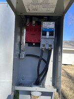
I'll get a pic of the inside of the pedestal, not sure how to hook multiple large wires to the breaker in there, probably some sort of lug I'm not familiar with. Also I'll have to remove bonding in my house panel but I think that will be easy. I seem to recall neutrals and grounds are on different busses already so it should be relatively easy, panel isn't "tidy" but pretty good.

Anyone see any potential issues? What lug is used to hook multiple wires to a 200A breaker properly?

Any wire recommendation? MHF is direct burial so I'd need it in conduit at the pedestal and up the wall on the outside of the house, how about through the attic? I know 4/0 for the hots but not sure what is needed for neutral and ground, looks like there are a couple choices, see attached screen shot.

Thanks!

BTW once the GF saw the cable run she was fine with trenching through the flower garden! :)

An added bonus is I can get the empty meter box off the wall in my sun room after those wires are dead.


IMG_0018.png
 
Last edited:

mike93lx

ALLIANCE MEMBER
Joined
Dec 9, 2013
Messages
37,840
Location
Richmond, VA
MHF requires conduit everywhere except underground. If you want to run something across rhe attic without conduit, switch to SER.

I would use the one with reduced neutral. It will make the wire a little less bulky

A Pic of the inside of the disconnect at the transformer would help, if you can get them. As for connecting those large cables together, split lugs with the right tape or Polaris connectors are the right way. Polaris are expensive, but simple
 
OP
B

bronc076

Well-known member
Joined
Jul 17, 2023
Messages
190
Location
Ozarks
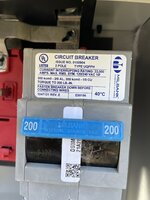
This just got a lot easier, I can add a 2nd breaker in the pedestal! Going to go with 4/0-4/0-2/0-4 Aluminum MHF and an additional 200 amp breaker for the shop circuit.


IMG_6546.jpeg


IMG_6547.jpeg

IMG_6548.jpeg
IMG_6549.jpeg
 
Last edited:
OP
B

bronc076

Well-known member
Joined
Jul 17, 2023
Messages
190
Location
Ozarks
I'll throw a couple ground rods out there too since the electrician working for the power company didn't do that when he installed the pedestal.

WOW that's an expensive breaker! I'm not sure this panel supports multiple 200 amp breakers. I'll have to research this pedestal. I don't need 200 in the shop, that's for sure.FullSizeRender.jpeg
 
Last edited:

dave*99

Well-known member
Joined
May 5, 2009
Messages
4,274
Location
Coastal NJ
This just got a lot easier, I can add a 2nd breaker in the pedestal! Going to go with 4/0-4/0-2/0-4 Aluminum MHF and an additional 200 amp breaker for the shop circuit.

WOW that's an expensive breaker! I'm not sure this panel supports multiple 200 amp breakers. I'll have to research this pedestal. I don't need 200 in the shop, that's for sure.

If I follow you correctly, you are referring to the 200A 2 pole Milbank breaker as the expensive one. I think you can't put 2 of those in there anyway. Because:

1708302941570.png

It would seem you are limited to 125A on the stabs available to power the shop.
At least that's how I read it.

Since the pedestal is rated for a maximum of 200A, plan accordingly.
 
Last edited:
OP
B

bronc076

Well-known member
Joined
Jul 17, 2023
Messages
190
Location
Ozarks
Thanks for the reply.

Yes I read that decal and did a lot of research today after I made those posts.

This evening I fired up everything in my house including electric heat, water heater, dryer, (gas oven left off), electric space heater, hair dryer, etc. Using my vintage analog current clamp I saw about 65 -70 amps on the phases in that bypassed meter box in the sun room. I might pick up a new current clamp and do it again but I'm not sure I could pull a constant 100A in this house if I tried.

My current plan is feed the house with 4/0-4/0-2/0-4 MHF (overkill but appropriate/code) from the existing 200A breaker, and for the shop feed I'll install a 90A Siemens QPH breaker and run 2-2-4-6 MHF to a 100A panel in the shop. My shop in AZ was fed with a 60A breaker and it never tripped in 20 years and I won't be doing much differently.

Does this seem like an appropriate approach?

Thank you!
 

dcg9381

Well-known member
Joined
Jun 20, 2018
Messages
11,883
Location
Austin, TX
Does this seem like an appropriate approach?
Well, Wylie is right that "load calc" is the right way to do it. I find these to be "very conservative" (meaning that are on the high side) - but their point is to be on the high side.

The one thing I see you missing in your "load test" is perhaps triggering aux heat strips (IE, emergency heat) - these can add a pretty good load, maybe 40-60A. Have an electric range? No electric oven. Electric dryer? Those are all power hogs.

You don't appear to have a huge power-hungry house. Absent an EV, a pool heater, a 50A hot tub, etc etc I'd guess that your SWAG is about right.

Really want to know you put a load measuring device on that box and get some real readings over time. That's how I do it. I use a "power monitor". Our peak loads at home are generally under 19KW but I don't let the house do emergency heat, we switch to propane during sub-freezing.

Again, swaggy, but I cannot outrun 90A in a 2400 sqft shop with AC, a hot tub, full kitchen, welder, etc.

I am not an electrician and my swag advice is worth exactly what you paid for it.
 

dave*99

Well-known member
Joined
May 5, 2009
Messages
4,274
Location
Coastal NJ
Thanks for the reply.

Yes I read that decal and did a lot of research today after I made those posts.

This evening I fired up everything in my house including electric heat, water heater, dryer, (gas oven left off), electric space heater, hair dryer, etc. Using my vintage analog current clamp I saw about 65 -70 amps on the phases in that bypassed meter box in the sun room. I might pick up a new current clamp and do it again but I'm not sure I could pull a constant 100A in this house if I tried.

My current plan is feed the house with 4/0-4/0-2/0-4 MHF (overkill but appropriate/code) from the existing 200A breaker, and for the shop feed I'll install a 90A Siemens QPH breaker and run 2-2-4-6 MHF to a 100A panel in the shop. My shop in AZ was fed with a 60A breaker and it never tripped in 20 years and I won't be doing much differently.

Does this seem like an appropriate approach?

Thank you!
The pedestal is rated 200A. The point of the load calc is to allow you to size the house breaker and the shop breaker properly.
200A plus 90A..... well that's way above the 200A rating of the pedestal.
 
To avoid these ads, REGISTER NOW!

dcg9381

Well-known member
Joined
Jun 20, 2018
Messages
11,883
Location
Austin, TX
The pedestal is rated 200A. The point of the load calc is to allow you to size the house breaker and the shop breaker properly.
200A plus 90A..... well that's way above the 200A rating of the pedestal.
He's got a 200A main breaker downstream of the pedestal and a 90A sub breaker from there... If I've got that right, he'll trip the main before he overloads the pedestal?

If he's feeding 90A + 200A from the pedestal, yea, that's not a good idea.
 

dave*99

Well-known member
Joined
May 5, 2009
Messages
4,274
Location
Coastal NJ
He's got a 200A main breaker downstream of the pedestal and a 90A sub breaker from there... If I've got that right, he'll trip the main before he overloads the pedestal?

If he's feeding 90A + 200A from the pedestal, yea, that's not a good idea.
I’m not 100% certain. I see a 6 stab bus fed from the top coming from the meter. 2 stabs carry the 200A main. The load cable exits at the bottom of the pedestal. The remaining 4 stabs are unoccupied and can be used for the shop.
 

wyliesdiesels

Well-known member
Joined
Aug 14, 2012
Messages
20,067
Location
Modesto, CA
Thanks for the reply.

Yes I read that decal and did a lot of research today after I made those posts.

This evening I fired up everything in my house including electric heat, water heater, dryer, (gas oven left off), electric space heater, hair dryer, etc. Using my vintage analog current clamp I saw about 65 -70 amps on the phases in that bypassed meter box in the sun room. I might pick up a new current clamp and do it again but I'm not sure I could pull a constant 100A in this house if I tried.

My current plan is feed the house with 4/0-4/0-2/0-4 MHF (overkill but appropriate/code) from the existing 200A breaker, and for the shop feed I'll install a 90A Siemens QPH breaker and run 2-2-4-6 MHF to a 100A panel in the shop. My shop in AZ was fed with a 60A breaker and it never tripped in 20 years and I won't be doing much differently.

Does this seem like an appropriate approach?

Thank you!
no, thats not how you do a load calc. a load calc is done by calculating the anticipated load.

this one works well


wyliesdiesels

Well-known member
Joined
Aug 14, 2012
Messages
20,067
Location
Modesto, CA
He's got a 200A main breaker downstream of the pedestal and a 90A sub breaker from there... If I've got that right, he'll trip the main before he overloads the pedestal?

If he's feeding 90A + 200A from the pedestal, yea, that's not a good idea.
incorrect. look at the diagrams of the panel he posted. his panel is wired in parallel. meaning the stabs on the left are not controlled by the 200a main. they are directly fed from the meter. "its called series wired P"
 

wyliesdiesels

Well-known member
Joined
Aug 14, 2012
Messages
20,067
Location
Modesto, CA
I’m not 100% certain. I see a 6 stab bus fed from the top coming from the meter. 2 stabs carry the 200A main. The load cable exits at the bottom of the pedestal. The remaining 4 stabs are unoccupied and can be used for the shop.
correct but those stabs are limited to 125a and the entire pedestal is limited to 200a. the 200a breaker does not feed the 4 stabs on the left since its wired in parallel per the diagram
 
OP
B

bronc076

Well-known member
Joined
Jul 17, 2023
Messages
190
Location
Ozarks
Thanks guys.

i pulled out my code book, read 220.82 and Annex D, looked at all my appliances, and came up with this. I didn't see Wylie's post till just now. If my math is right and I'm interpreting the book correctly it comes out to 115 amps load on the house. I'll bounce that off the link Wylie provided to check my math. Spreadsheet pic attached.
 

Attachments

  • IMG_0027.png
    IMG_0027.png
    1.3 MB · Views: 28
OP
B

bronc076

Well-known member
Joined
Jul 17, 2023
Messages
190
Location
Ozarks
Well, Wylie is right that "load calc" is the right way to do it. I find these to be "very conservative" (meaning that are on the high side) - but their point is to be on the high side.

The one thing I see you missing in your "load test" is perhaps triggering aux heat strips (IE, emergency heat) - these can add a pretty good load, maybe 40-60A. Have an electric range? No electric oven. Electric dryer? Those are all power hogs.

You don't appear to have a huge power-hungry house. Absent an EV, a pool heater, a 50A hot tub, etc etc I'd guess that your SWAG is about right.

Really want to know you put a load measuring device on that box and get some real readings over time. That's how I do it. I use a "power monitor". Our peak loads at home are generally under 19KW but I don't let the house do emergency heat, we switch to propane during sub-freezing.

Again, swaggy, but I cannot outrun 90A in a 2400 sqft shop with AC, a hot tub, full kitchen, welder, etc.

I am not an electrician and my swag advice is worth exactly what you paid for it.
You are correct we do not have a power hungry house except for electric heat which I augment with a fire in the fireplace when it gets below 20. No hot tubs or heated floors, just normal appliances and a gas range in a 1600 sqft house the two of us live in. I just posted two calculations using seemingly different methods, my interpretation came out higher but I errored on the high side and possibly missed something on the 2nd calc.
 

mike93lx

ALLIANCE MEMBER
Joined
Dec 9, 2013
Messages
37,840
Location
Richmond, VA
You are correct we do not have a power hungry house except for electric heat which I augment with a fire in the fireplace when it gets below 20. No hot tubs or heated floors, just normal appliances and a gas range in a 1600 sqft house the two of us live in. I just posted two calculations using seemingly different methods, my interpretation came out higher but I errored on the high side and possibly missed something on the 2nd calc.
I bet you would be hard pressed to find an instance when you are actually drawing over 60a.
 

dcg9381

Well-known member
Joined
Jun 20, 2018
Messages
11,883
Location
Austin, TX
incorrect. look at the diagrams of the panel he posted. his panel is wired in parallel. meaning the stabs on the left are not controlled by the 200a main. they are directly fed from the meter. "its called series wired P"
Thanks for the correction. In that case to stay safe, why not just drop the house main breaker to something lower than can support the wire size and run (I'm assuming) 60A over to the shop? That's what I'd do if split out of the pedestal and not behind a breaker.

Otherwise split it subsequent to the 200A main. We see this with 320A service and 2 x 200A panels. I assume there is a way to do this with 200A service for not a ton of change?
 
OP
B

bronc076

Well-known member
Joined
Jul 17, 2023
Messages
190
Location
Ozarks
Max load is 200a

Do a load calc on the house which will tell you what you have left for the shop.
The pedestal is rated 200A. The point of the load calc is to allow you to size the house breaker and the shop breaker properly.
200A plus 90A..... well that's way above the 200A rating of the pedestal.


I tried to interpret the NEC book and do a load calculation like in Annex D. It was a bit confusing as it appears there is a different calculation for services larger than 100A so I'm probably reading it wrong. The various percentages were confusing to a novice. Regardless both mine and the one using the Mike Holt link came in way under 200. This code book is tricky to understand, lots of references to other sections, it's a real page turner!

Typically the conversation here about loads and breakers and panel size winds up with "its perfectly fine for the sum of the breaker sizes to exceed the panel rating, breakers protect the wire down stream" I'd imagine that's only in a panel with a main, or a sub panel being fed from a breaker in another panel with appropriately sized breaker and wires. All for the purpose of preventing fire. Since I'm dealing with a pedestal fed directly from the meter with no main protection is there a part of the code that specifically deals with this application? While the chances of me drawing greater than 200A continuously ( or ever ) is extremely low, I'd still like to read the code. I do see the concern of having 290A worth of breakers in a 200A pedestal. Is this a code violation or just a bad practice? I do understand the risk to the pedestal.

Thanks!
[edit] this is all very educational and thank you for your input!
 

dave*99

Well-known member
Joined
May 5, 2009
Messages
4,274
Location
Coastal NJ
The pedestal is rated for 200A. Nothing upstream of the group of breakers protects the bus in the pedestal. You have to limit the breaker total to 200A.

In your service panel you have a main breaker. It protects the bus. Put 1000A worth of branch breakers in your main panel and the 200A main breaker limits the bus current to 200A.
 

wyliesdiesels

Well-known member
Joined
Aug 14, 2012
Messages
20,067
Location
Modesto, CA
The pedestal is rated for 200A. Nothing upstream of the group of breakers protects the bus in the pedestal. You have to limit the breaker total to 200A.

In your service panel you have a main breaker. It protects the bus. Put 1000A worth of branch breakers in your main panel and the 200A main breaker limits the bus current to 200A.
incorrect.

The bus in OPs pedestal (which is the service panel/main panel) is parallel wired. the 200a breaker only protects the bus feeding the 200a breaker. the 200a breaker does not feed or protect the other parts of the bus that feed the other 4 bus stabs.

if his pedestal was wired in series, then your comment would be correct. see the diagrams the OP posted in #15

also you are mixing up main panel/service panel and subpanel. the panel in the OPs house is NOT the main panel or service panel. it is a subpanel. The main panel/service panel is the pedestal.
 

dave*99

Well-known member
Joined
May 5, 2009
Messages
4,274
Location
Coastal NJ
incorrect.

The bus in OPs pedestal (which is the service panel/main panel) is parallel wired. the 200a breaker only protects the bus feeding the 200a breaker. the 200a breaker does not feed or protect the other parts of the bus that feed the other 4 bus stabs.

if his pedestal was wired in series, then your comment would be correct. see the diagrams the OP posted in #15

also you are mixing up main panel/service panel and subpanel. the panel in the OPs house is NOT the main panel or service panel. it is a subpanel. The main panel/service panel is the pedestal.
Maybe I didn't explain my thoughts clearly as I don't understand what is incorrect.

I tried to answer the OP's question about why you can put branch breakers in a hypothetical panel that total up much higher than the main. I was not referring to his panel. Hence my example. I was trying to differentiate why he can't fill the pedestal in the same fashion.

There is no breaker feeding the bus in the pedestal, rather you protect that bus by limiting the total loads you connect to it. The sum of the breakers on that panel bus should be limited to 200A.

Are all 6 stabs bussed to the meter lugs directly? Or are the 4 on the left separated from the 2 on the right?
 
Last edited:

wyliesdiesels

Well-known member
Joined
Aug 14, 2012
Messages
20,067
Location
Modesto, CA
Maybe I didn't explain my thoughts clearly as I don't understand what is incorrect.

I tried to answer the OP's question about why you can put branch breakers in a hypothetical panel that total up much higher than the main. I was not referring to his panel. Hence my example. I was trying to differentiate why he can't fill the pedestal in the same fashion.

There is no breaker feeding the bus in the pedestal, rather you protect that bus by limiting the total loads you connect to it. The sum of the breakers on that panel bus should be limited to 200A.

Are all 6 stabs bussed to the meter lugs directly? Or are the 4 on the left separated from the 2 on the right?
Awww ok i misunderstood you

All stabs are directly connected to meter pan since they are wired in parallel.
 
OP
B

bronc076

Well-known member
Joined
Jul 17, 2023
Messages
190
Location
Ozarks
Thanks guys I think I have a handle on this now.

There are no ground rods at the Pedestal which I need to fix. Is there another method besides driving rods into the ground? Can I put some length of cable in the ditch and backfill over it to meet the requirement? That would be easier.

Thanks!
 

dcg9381

Well-known member
Joined
Jun 20, 2018
Messages
11,883
Location
Austin, TX
There are no ground rods at the Pedestal which I need to fix. Is there another method besides driving rods into the ground? Can I put some length of cable in the ditch and backfill over it to meet the requirement? That would be easier.
Around here the ground is really hard, they put a jackhammer on top of the ground rod to drive it. You start on top of a ladder and drive them in.

You "should" do it. Do you "have" to do it? That's not clear to me, it was permitted (and likely inspected) at one time. Unless you're making a major change, you typically don't have to bring it up to code. Your shop should get it's own ground as a separate building.

Our pedestals are on concrete, there is a means of connecting a ground to the steel within the concrete (called UFER) but you have to set the up when it's poured and I'm sure there is some sort of minimum area.
 
OP
B

bronc076

Well-known member
Joined
Jul 17, 2023
Messages
190
Location
Ozarks
Do you guys know where the bonding screw is on this old CH panel? I'm going to need to isolate the grounds from the neutrals as this is becoming a sub panel. In an earlier post I said this was tidy in here but I must have been thinking of a different house. Honestly it would be easier to install a new isolated neutral bus on the right hand side and move the neutrals over. 220 circuits from top to bottom are furnace, range (off, got gas), water heater, dryer, air conditioner. I'd rather leave those big old wires alone and just move my neutrals over. I know typically adding a new ground bus is recommended, assuming I can't separate the existing busses.

IMG_6615.jpeg
 
Last edited:
To avoid these ads, REGISTER NOW!
Top Bottom