To avoid these ads, REGISTER NOW!

Pressure switch vs. 240 VAC mag starter question

FTG-05

Well-known member
Joined
Oct 11, 2012
Messages
1,548
Location
TN
I need help understanding how to connect my air compressor pressure switch to my magnetic starter for my franken-pressor.

It has a 5 HP IR motor (22.8 amps) with a 440A LeRoi-Dressor pump and an 80 gallon IR tank. When I bought it, it only had a pressure switch powering the motor. It worked, but from reading GJ, I knew that using only a pressure switch for a 5 hp motor was bad. Hence, I bought a new 25 amp pressure switch from Surplus Center and a 7.5 hp magnetic starter from Weg/Temco (the L-D pump can be used with a 5 or 7.5 hp motor; I wanted to be able to upgrade later if this motor went out).

Here is the pressure switch: https://www.surpluscenter.com/Water...our-Port-25-Amp-Pressure-Switch-4-1823-H4.axd

Here is the motor starter: https://temcoindustrial.com/weg-esws-50v24e-rm38-motor-starter.html

Pic of the inside of the pressure switch; ignore the current wiring, I'm going to redo it. The center two terminals are marked "Line"; the top two are marked "Motor" (the bottom two are for the grounds).

4SIkUnX.jpg


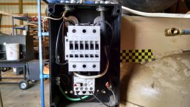
Pics of the motor controller (again, ignore the white wiring just below the top white box):

T1iWP8X.jpg


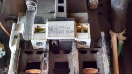
On top of the above pic is the coil, which is not visible. Here's a pic of the coil; note that this motor controller has a 240 VAC coil - which is where my question is going to come from. The lugs for L1 and L2 are just barely visible at the bottom of the pic. The coil terminals are marked "A1" (left) and "A2" (right):

ty7AJuK.jpg


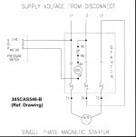
And here is the wiring diagram for this motor controller from inside the MC cover (it also repeated on the 2 page .pdf data sheet on the Weg/Temco MC site). Note the terminals marked "A1" and "A2" just above the center of the diagram.

MWHAnDf.jpg


So my question is as follows:

Since I have a 220 VAC motor controller coil, I then need 220 VAC delivered to the MC coil from the pressure switch - Yes?

And since a 220 VAC circuit consists of 2 wires (hot-hot; ignoring the ground):

I then need to have 220 VAC (hot-hot) to the two terminals marked "Line" on the pressure switch, then 2 wires (hot-hot) from the terminals marked "Motor" from the pressure switch going to the two terminals (hot-hot) to the MC coil terminal marked "A1" and A2" - Yes?

Or am I missing something and over complicating this?

Please help me get from the pressure switch to the motor controller without burning up the motor, the pump, my shop, my house and the surrounding 38 acres of my woods.

Thanks!
 
To avoid these ads, REGISTER NOW!

454ragtop

Well-known member
Joined
Mar 24, 2008
Messages
5,011
Location
Carver, MA
Pics aren't showing up, please post directly to the site.

By the way, you don't need a 25 amp pressure switch, the current needed to switch the mag starter is less than an amp.
 
OP
F

FTG-05

Well-known member
Joined
Oct 11, 2012
Messages
1,548
Location
TN
Well ****! Let me try again:

I need help understanding how to connect my air compressor pressure switch to my magnetic starter for my franken-pressor.

It has a 5 HP IR motor (22.8 amps) with a 440A LeRoi-Dressor pump and an 80 gallon IR tank. When I bought it, it only had a pressure switch powering the motor. It worked, but from reading GJ, I knew that using only a pressure switch for a 5 hp motor was bad. Hence, I bought a new 25 amp pressure switch from Surplus Center and a 7.5 hp magnetic starter from Weg/Temco (the L-D pump can be used with a 5 or 7.5 hp motor; I wanted to be able to upgrade later if this motor went out).

Here is the pressure switch: https://www.surpluscenter.com/Water-...-4-1823-H4.axd

Here is the motor starter: https://temcoindustrial.com/weg-esws...r-starter.html

Pic of the inside of the pressure switch; ignore the current wiring, I'm going to redo it. The center two terminals are marked "Line"; the top two are marked "Motor" (the bottom two are for the grounds). (See all pics below, in order).

Pics of the motor controller (again, ignore the white wiring just below the top white box):

On top of the above pic is the coil, which is not visible. Here's a pic of the coil; note that this motor controller has a 240 VAC coil - which is where my question is going to come from. The lugs for L1 and L2 are just barely visible at the bottom of the pic. The coil terminals are marked "A1" (left) and "A2" (right):

And here is the wiring diagram for this motor controller from inside the MC cover (it also repeated on the 2 page .pdf data sheet on the Weg/Temco MC site). Note the terminals marked "A1" and "A2" just above the center of the diagram.


So my question is as follows:

Since I have a 220 VAC motor controller coil, I then need 220 VAC delivered to the MC coil from the pressure switch - Yes?

And since a 220 VAC circuit consists of 2 wires (hot-hot; ignoring the ground):

I then need to have 220 VAC (hot-hot) to the two terminals marked "Line" on the pressure switch, then 2 wires (hot-hot) from the terminals marked "Motor" from the pressure switch going to the two terminals (hot-hot) to the MC coil terminal marked "A1" and A2" - Yes?

Or am I missing something and over complicating this?

Please help me get from the pressure switch to the motor controller without burning up the motor, the pump, my shop, my house and the surrounding 38 acres of my woods.

Thanks!
 

Attachments

  • IMG_20180403_112401322_HDR (Large).jpg
    IMG_20180403_112401322_HDR (Large).jpg
    146.8 KB · Views: 45
  • IMG_20180403_112335472_HDR (Large).jpg
    IMG_20180403_112335472_HDR (Large).jpg
    149.6 KB · Views: 45
  • IMG_20180403_112350404_HDR (Large).jpg
    IMG_20180403_112350404_HDR (Large).jpg
    148.3 KB · Views: 43
  • IMG_20180403_112445116 (Large).jpg
    IMG_20180403_112445116 (Large).jpg
    131.2 KB · Views: 61

TRWham

Well-known member
Joined
Aug 11, 2017
Messages
1,999
Location
East Cobb County, Georgia
You need only use one side of the pressure switch to control the contactor. Pick up your 240V voltage off of the line side of one leg (let's say L1) at your starter. Run that to the Line terminal on the pressure switch, then connect to the Load side of that same set of contacts and run it back to the contactor coil in the starter. Connect the other side of the coil to the other leg (L2) on the line side again. This wiring sends 240V to the pressure switch, which will then send it to the contactor coil whenever it is closed and calling for the compressor to run.

One thing you might be missing is if there are other control inputs (e.g. motor overload, oil pressure safety, manual switch) that should be wired so that they can also break the control circuit and shut off the compressor.
 
OP
F

FTG-05

Well-known member
Joined
Oct 11, 2012
Messages
1,548
Location
TN
You need only use one side of the pressure switch to control the contactor. Pick up your 240V voltage off of the line side of one leg (let's say L1) at your starter. Run that to the Line terminal on the pressure switch, then connect to the Load side of that same set of contacts and run it back to the contactor coil in the starter. Connect the other side of the coil to the other leg (L2) on the line side again. This wiring sends 240V to the pressure switch, which will then send it to the contactor coil whenever it is closed and calling for the compressor to run.

One thing you might be missing is if there are other control inputs (e.g. motor overload, oil pressure safety, manual switch) that should be wired so that they can also break the control circuit and shut off the compressor.

If I understand you right:

MC L1 to PS L1
PS M1 to MC A1
MC L2 to MC A2

MC = Motor Controller
PS = Pressure Switch
L1/L1 is the Line side of power from the CB box)
M1 = Motor side of PS
A1/A2 is the motor controller 220 vac controller

Sound right?
 
OP
F

FTG-05

Well-known member
Joined
Oct 11, 2012
Messages
1,548
Location
TN
Seems so, but you need to be sure. With no insult intended, I will say you seem a bit tentative regarding this wiring. Do you have anyone local you can consult and who can put his/her eyes on your installation?

None taken. And you're exactly right: I am very hesitant wiring this motor controller because it's wiring diagram makes no sense to me.

I've wired everything from the shop breaker box, to the compressor on-off switch, through the compressor breaker box (a late addition based on adding a compressor light circuit - safely - from a thread here on GJ). Everything works. Now, I just need to go from the Pressure Switch to the Motor Controller - safely.

220 VAC is nothing to play around with. Burning up a $120 motor controller isn't either, never mind a $500 5 hp motor.
 
Last edited:
To avoid these ads, REGISTER NOW!

TRWham

Well-known member
Joined
Aug 11, 2017
Messages
1,999
Location
East Cobb County, Georgia
How did you wire that compressor On/Off switch? Does it control the contactor via the coil? If so, you just need to put the pressure switch in series with it so that either can break the control circuit. If you are breaking the power from the panel directly with the switch, then that won't be an option.
 
OP
F

FTG-05

Well-known member
Joined
Oct 11, 2012
Messages
1,548
Location
TN
How did you wire that compressor On/Off switch? Does it control the contactor via the coil? If so, you just need to put the pressure switch in series with it so that either can break the control circuit. If you are breaking the power from the panel directly with the switch, then that won't be an option.

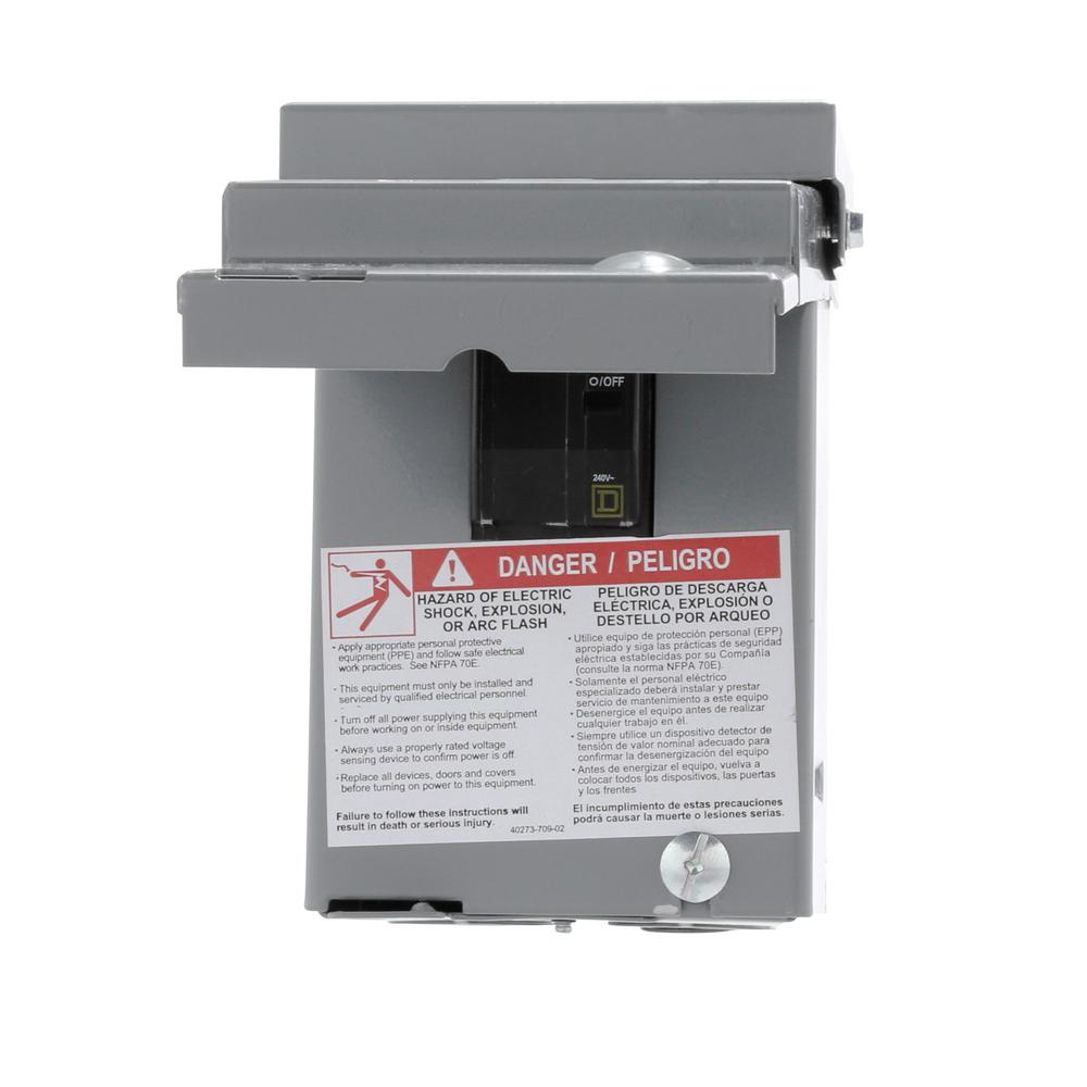
TR, it's a HD 60 amp non-fused power switch; somebody posted about it in another thread.

Pic and link: https://www.homedepot.com/p/Square-...kW-Non-Fuse-AC-Disconnect-QO200TRCP/202353314

square-d-electrical-disconnects-qo200trcp-e1_1000.jpg
 

TRWham

Well-known member
Joined
Aug 11, 2017
Messages
1,999
Location
East Cobb County, Georgia
That switch is killing the entire supply to the compressor. If you follow that Eaton diagram for the pressure switch you'll be in business. The control logic is the same.
 
OP
F

FTG-05

Well-known member
Joined
Oct 11, 2012
Messages
1,548
Location
TN
That switch is killing the entire supply to the compressor. If you follow that Eaton diagram for the pressure switch you'll be in business. The control logic is the same.

That's the point. Other than providing power it doesn't control the compressor.

I'll be doing the Eaton diagram work this afternoon.

Thanks to all that helped, I appreciate it! :beer:
 
OP
F

FTG-05

Well-known member
Joined
Oct 11, 2012
Messages
1,548
Location
TN
Here one for an Eaton starter. They are all pretty much the same.

Worked like a charm. Hooked everything up - except for the motor hot leads.

Turned on the on-off switch, turned the pressure switch and the motor controller clicked on. After turning it on-off several times, I confirmed the 220 VAC at the T1/T3 leads at the bottom of the controller.

Turned everything off and connected the two motor hot leads, buttoned everything up - motor and compressor started right up.

I may have a leak at the pressure switch unloader valve. After exercising it a couple times, it might be working ok; I'll see what the pressure is tomorrow AM when I go into my shop.


Thanks again to everyone who helped, especially engineer for that diagram, I really appreciate it! :beer:
 
To avoid these ads, REGISTER NOW!
Top Bottom