To avoid these ads, REGISTER NOW!

Put on your Engineer Hats and Gather 'Round

MrSurly

Well-known member
Joined
Jan 15, 2014
Messages
1,671
Location
East Texas
Ok, folks, I need some guidance with my "plan" to add a loft (or two) in my new post frame 30x40x14.

I want to add loft storage in about 20% of the building.

I THINK I can do this:

  • Without hanging anything from the trusses
  • Without using any lally posts or other floor support
  • Hanging the loft floor from a full-span I-beam on top of the doubled header
  • joists anchored to a ledger added across the 6x6 posts.
  • using I-beams that I already have.


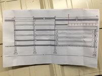
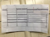
I've attached a sketch or two to try to make sense of it.

The main beam would span 30' and rest on the 2x10 (double)header.

The top of the header(s) (ceiling height) is 14' 2".

I would create hangers (steel or wood?) that would hang from the I beam 7'. To these hangers I would mount a ledger that would mount joist hangers. Joists would attach to a ledger mounted on the posts of the gable end wall (the North wall)


The questions begin with
  1. what span is workable with 2x6 or 2x8s?
  2. Joist selection and allowable length will determine the size of the loft and the placement of the I beam
  3. What lumber should I use if I wanted to go 10,12,14 foot?
  4. maybe metal C-purlin would be better?
  5. The I beams I have: S 10 x 25.4 lb (10.00" x .311" x 4.661")
  6. Does this beam, spanning 28.6' have a chance of doing what I want?
  7. Floor loading will be light (christmas boxes, attic stuff, no engine blocks or ship anchors)
  8. My target would be a 14x16 loft eight foot off the floor
  9. Another loft area might be good over the garage door shown, at 10 foot height


Any input would be appreciated. I'm not going to touch the trusses, and don't worry about the stairs, I have a fix for the stairs.

I don't know if there is any way to even approach a 14' span with two-by lumber, but maybe glu-lam or metal?

I'll attach sketches in a minute.
24034ab3881cd2debba7393f7c226c04.jpg
9cdc6845fa567285d18f940528884ad5.jpg
141b75c2f6158790ac3be639849a7737.jpg
 

Attachments

  • 24034ab3881cd2debba7393f7c226c04.jpg
    24034ab3881cd2debba7393f7c226c04.jpg
    631 KB · Views: 0
  • 9cdc6845fa567285d18f940528884ad5.jpg
    9cdc6845fa567285d18f940528884ad5.jpg
    669.4 KB · Views: 0
  • 141b75c2f6158790ac3be639849a7737.jpg
    141b75c2f6158790ac3be639849a7737.jpg
    577.9 KB · Views: 0
Last edited:
To avoid these ads, REGISTER NOW!
Joined
Jul 24, 2016
Messages
3,371
They are expensive but LVLs (laminated veneer lumber) are extremely strong. Waiting for the sketches.....
 
OP
M

MrSurly

Well-known member
Joined
Jan 15, 2014
Messages
1,671
Location
East Texas
They are expensive but LVLs (laminated veneer lumber) are extremely strong. Waiting for the sketches.....

Pics inserted.

Not shown in the sketch is that the headers that are above the 18' garage door are actually 18" LVLs. The rest of the headers are 2x10s (2 of them, on inside and outside of the 6x6 posts)
 

matt_i

Well-known member
Joined
Mar 14, 2008
Messages
10,802
Location
SE Michigan
I have done no calcs, but an S10 x 25# seems light for 30' span.

Have to come up with an actual floor loading, 40psf seems about right.

The biggest problem might come from the new load on the posts + cookies being greater than > 2000 psf ground pressure....that would cause a column to sink....
 

wssix99

Well-known member
Joined
Mar 2, 2011
Messages
5,172
Location
Chicago, IL
Ok, folks, I need some guidance with my "plan" to add a loft (or two) in my new post frame 30x40x14.

Your design is really complicated, made worse by the garage doors underneath the structures.

Is your intent to do this without a licensed engineer's help?

If so, it makes sense to strategize ahead of time to lower your cost.

If not, I would recommend simplifying your design to create a structure that you can design and control. (The current plan is exotic.)


I THINK I can do this:

  • Without hanging anything from the trusses
  • Without using any lally posts or other floor support
  • Hanging the loft floor from a full-span I-beam on top of the doubled header
  • joists anchored to a ledger added across the 6x6 posts.
  • using I-beams that I already have.

- You are going to need to add supports to the floor. Your structure is not designed for the point loads that your beams will put into the walls. So, if you want clear spans - you can do that. However, (at a minimum) you will likely need to add columns in the walls that take those point loads to the ground/foundation.

- Likewise, your double header is not designed for this, either. These beams will concentrate large forces (The weight of the entire floor and everything on it.) to one point, which they won't be able to handle mid-span.

- You are going to need to purchase new beams. Unless your building was originally designed for what you are adding, it will not have excess design capacity for additional floors. Even if it did, it would not give you the versatility to add point loads (from the beams) wherever you want them.

So, if you want to utilize existing structure, you'd need to have an engineer calculate what overhead you have left in that structure and where you can add loads. From there, you would work backwards to see what you can add. I expect that this exercise will be very expensive and give you very little return.


The simple/path of least resistance would be to slide new beams (probably steel if you want that 30' clear span) into the structure, add columns to support them in the walls, and rest your joists on top of the steel. The structure above your garage doors and the door headers will also not be able to support half of these floors' loads, so you will likely need to re-design the headers over the doors and add more across your current posts.


The questions begin with
  1. what span is workable with 2x6 or 2x8s?
  2. Joist selection and allowable length will determine the size of the loft and the placement of the I beam
  3. What lumber should I use if I wanted to go 10,12,14 foot?
  4. The I beams I have: S 10 x 25.4 lb (10.00" x .311" x 4.661")
  5. Does this beam, spanning 28.6' have a chance of doing what I want?

- Your joist selection would come last and is a function of the spacing, length, and other factors. For a 12' span, I would not expect that you would be able to get by with something as small as a 2X6.

- It looks like you are just on the edge of what your current beam would take; assuming that you add structure/columns to the walls to pickup the loads properly. The other thing to expect is that this could also leave you with a "springy" floor. (Even if it can take the load, it may bounce a little as you walk around.)

- You'll need to change the orientation of the green joists so everything goes the same way. Adding that secondary beam creates another point load, which may turn out to be a deal breaker for using your existing beam. (This also makes the do-it-yourself calculations much more difficult.)
 
OP
M

MrSurly

Well-known member
Joined
Jan 15, 2014
Messages
1,671
Location
East Texas
Some interesting points.
As to the complication of the design, for the discussion let's forget about the loft over the 18' door (the secondary I-beam and the green joists); this was afterthought anyway and intended for really light loading, not a people space.

Back to the 30' beam resting on the double headers.
The beam can theoretically be placed *any* distance from the gable wall and the joist length will determine that. Of course, I have to figure out what is a workable (and worthwhile) happy medium between too small of a space and too big to afford to build safely.
The building was first spec'ed by a pole barn contractor the way 'those guys' would build it, essentially borderline flimsy. The double headers they use are 2x8s.
I then (city requirement as well) hired an engineer to make it correct. The engineer added quite a bit of beef; trusses got lateral bracing, headers went to 2x10, the header over the wide door became two 18" LVLs (pretty beefy stuff) and fancy fasteners were spec'ed.

The post holes were bored 18", two bags of Sakrete in each before the posts. A slab (4" min with rebar) was then poured.

Yes, I could hire the engineer again. I'm hoping to avoid that added expense and of course, I'm hoping to get all the feedback I can and I do want to build safe.

I feel like the engineer 'overbuilt' it somewhat (of course) and I'm hoping to utilize some of that headroom but not all of it.

Some thoughts on mentioned points:
[#]discard the green joist area and the secondary beam
[#]I can readily add a wood or steel post within the wall to support the point load on the header if that post can rest on top of the slab to spread the load (thinking inverted 'T' shape) but only on that side, I can't do that for the LVLs over the door.
[#]I can incorporate twist resistance for the I beam by lateral connection to the trusses (where not already provided by the 'hangers' )
[#]I have two of the beams; I can use both, married, if that would help
[#]I could use one beam to make an "A- frame" over the garage door , posts to the slab right at the door jamb area to avoid loading the LVLs.

I NEED the loft area or the promise of the new shop is stymied by loss of shop space to rudimentary storage duty.

What do y'all think of supporting any added point load by resting it on the slab?
A 6x6 tinmber, 4' long, laid against the wall with a post on it, positioned between the headers for lateral support. Beam(s) on top of the new post.
 
Last edited:

matt_i

Well-known member
Joined
Mar 14, 2008
Messages
10,802
Location
SE Michigan
Just some other random thoughts...any time you marry wood and steel its asking for extra work (extra details + analysis).

The vertical legs you show to the I-beam would typically need "structural steel clips" which involves a T-shaped cross section underneath, then its clamped to the bottom flanges with the idea the lines of contact are up very close to the web. Drilling the flange and direct-bolting is an option but it messes up the integrity of the flange which is carrying the max tension in the section...thus additional overkill in sizing the main beam is driven...

Do you have a method to raise the beam into place (?) 25#/ft * 30ft = 750# is not trivial overhead when it has to be swiveled and inched into position.

I also think there's going to need some detailing around the bearing area atop the 2x10s (if those were structurally adequate)...the vertical stress on the bearing area could overtax and deform the wood. Need to have some way to assure the beam doesn't roll over should there be a side load. Need to look at the Iyy especially on a long S-shape beam for same side-loading.

The engineering analysis is important when you are considering suspending loads over people...the cost of being wrong is potentially quite high...
 
OP
M

MrSurly

Well-known member
Joined
Jan 15, 2014
Messages
1,671
Location
East Texas
The vertical 'hangers' in the drawing are there to indicate that I have no idea how to properly fashion this attachment and only a vague idea where they would go. My redneck brain says weld a tab to the beam/ bolt wood to the tab OR just use angle iron to form the hangers, possibly making a 'box' around the beam to avoid welding on it (also providing twist resistance).

Stepping back a little, I need to know (without considering any beams, headers or point load topics) a more fundamental answer: how much span can be bridged using common two-buy lumber? Assume for this exercise that the support structure at each end is infinitely strong and the joists will be decked with a single layer of... 3/4 ply?.

Another basic question: forgetting the beams I have... if this were your building, how would YOU add a loft?
 

lakeroadster

Well-known member
Joined
Jan 19, 2015
Messages
5,166
Location
Central Colorado
Lofty Goals

Another basic question: .......if this were your building, how would YOU add a loft?

If it were an existing building... I'd core and drill the slab to determine slab strength and thickness, then design a free standing loft not attached to the building structure.

If it were a green field building... I'd design it such that the trusses would carry the load.
 

RWorth

Well-known member
Joined
Aug 29, 2016
Messages
592
Location
Cape Cod , Mass.
That seems like a lot of work for nothing, why don't you put your I-beam on jacks in the wallsl at the loft floor height? I don't see why you would want to hang the floor?
 

GMCGarage

Well-known member
Joined
Jan 31, 2017
Messages
1,264
The vertical 'hangers' in the drawing are there to indicate that I have no idea how to properly fashion this attachment and only a vague idea where they would go. My redneck brain says weld a tab to the beam/ bolt wood to the tab OR just use angle iron to form the hangers, possibly making a 'box' around the beam to avoid welding on it (also providing twist resistance).

Stepping back a little, I need to know (without considering any beams, headers or point load topics) a more fundamental answer: how much span can be bridged using common two-buy lumber? Assume for this exercise that the support structure at each end is infinitely strong and the joists will be decked with a single layer of... 3/4 ply?.


Another basic question: forgetting the beams I have... if this were your building, how would YOU add a loft?

#2 SYP, 10psf DL and 40psf LL 2x8 will span 12 ft. for reference

If I was adding a loft, I would have it independent of the main structure so I dont compromise anything there. Maybe use main structure to staiblize.

For your 30' span, deflection will kill you. Also the double 2x10 isnt going to support a 30' beam and load.
 
OP
M

MrSurly

Well-known member
Joined
Jan 15, 2014
Messages
1,671
Location
East Texas
If it were an existing building... I'd core and drill the slab to determine slab strength and thickness, then design a free standing loft not attached to the building structure.

Freestanding might be it.

That seems like a lot of work for nothing, why don't you put your I-beam on jacks in the walls at the loft floor height? I don't see why you would want to hang the floor?
Because I was planning on just resting the beam on top, for one thing but also because of the garage door location.
#2 SYP, 10psf DL and 40psf LL 2x8 will span 12 ft. for reference

If I was adding a loft, I would have it independent of the main structure so I don't compromise anything there. Maybe use main structure to stabilize.

For your 30' span, deflection will kill you. Also the double 2x10 isn't going to support a 30' beam and load.

Two points that I wonder about:
1. assuming I could sufficiently support the header that would be toward the middle of the room (independent of the building) what about attaching the "wall end" of the joists to the posts of the gable wall? I would think that the posts of the building would to be able to carry *some* additional load but I don't know if that's a thousand pounds or a hundred.

2. I have two of these I-beams. Does using two of them (joined or separately placed) make the 30' span possible? *assuming independent supports*


Addressing an earlier question: Yes, I have the means to lift and place the beam(s) and to cut/weld if necessary.


Y'all keep at it, I'm learning stuff!
 
To avoid these ads, REGISTER NOW!

GMCGarage

Well-known member
Joined
Jan 31, 2017
Messages
1,264
Freestanding might be it.


Because I was planning on just resting the beam on top, for one thing but also because of the garage door location.


Two points that I wonder about:
1. assuming I could sufficiently support the header that would be toward the middle of the room (independent of the building) what about attaching the "wall end" of the joists to the posts of the gable wall? I would think that the posts of the building would to be able to carry *some* additional load but I don't know if that's a thousand pounds or a hundred.

2. I have two of these I-beams. Does using two of them (joined or separately placed) make the 30' span possible? *assuming independent supports*


Addressing an earlier question: Yes, I have the means to lift and place the beam(s) and to cut/weld if necessary.


Y'all keep at it, I'm learning stuff!

I think all possibilities are there if you want to spend the money. What you have right now wont support it, and based on the loads could be catastrophic failure. You are doing big spans to an existing building. Steel and wood mixed. You have alot going on.
Spend $500-1000 and get it engineered, that way you know its not going to kill someone.
I dont think the engineers on here are going to design it for you online. We will give you pointers and suggestions though.
 

firebirdparts

Well-known member
Joined
Jun 8, 2016
Messages
10,754
Location
Kingsport, TN
Stepping back a little, I need to know (without considering any beams, headers or point load topics) a more fundamental answer: how much span can be bridged using common two-buy lumber? Assume for this exercise that the support structure at each end is infinitely strong and the joists will be decked with a single layer of... 3/4 ply?.

Typical construction in your house, with 40 lb/square foot live design load + 10 lb/square feet dead, would be 2 by 10's on 16" centers. This is good for 14 feet with any framing lumber you find. Southern yellow pine gets you up to 16. I guess this is why so many ranch houses are 28 feet wide. I guess.

Occasionally you'll see 2 by 12's on 12" which is basically maxed out. That is good for about 18. Yellow pine you could go 22.
 

Firebrick43

Well-known member
Joined
May 12, 2015
Messages
14,419
Location
West central Indiana
I have a w12 x 26# beam under my house. Post are at 14.5' spacing per engineer. That beam will be massive to freespan a 30'. Neighbor has a 30' loft, doubled lvl beam 11.5" deep, supported in the middle.
 
OP
M

MrSurly

Well-known member
Joined
Jan 15, 2014
Messages
1,671
Location
East Texas
If two S10/25.4 I-beams are joined together, by whatever method, does this help their rating?


Sent from my iPhone using Tapatalk
 

roguegts

Well-known member
Joined
Aug 1, 2013
Messages
189
Get in touch with the engineer that originally designed the structure and let them add it on. You're way outside the scope of a safe simple add-on in my opinion. That 30' span will require hanging a big chunk of steel and preferably be supported by steel posts or concrete columns independent of the perimeter walls.

What was the slab designed for? standard vehicular loads? forklifts? commercial lifts? Is it a standard rebar/pour or post-tension?
 

Firebrick43

Well-known member
Joined
May 12, 2015
Messages
14,419
Location
West central Indiana
If two S10/25.4 I-beams are joined together, by whatever method, does this help their rating?


Sent from my iPhone using Tapatalk

If you used a s10x25 beam using a simple point load calculator with a 40 lbs per square foot load in the center I get 2.5 inches of sag in the center

This is just a par of men standing in the center. Now add thousands of pounds dead weight for the joist,osb, things stored up there, even two beams side by side, it ain't going to work. You need either a post or two, a massive beam of maybe 20"+ deep, or make that end of loft a structual truss wall. But you NEED an engineer here.
 
OP
M

MrSurly

Well-known member
Joined
Jan 15, 2014
Messages
1,671
Location
East Texas
To all who have replied; Thanks, guys, and I GET it.
I had hoped to have a loft AND a clear span and it has become clear that it can't happen. The scope of the plan, physics, safety; to meet all three parameters would require stupid levels of money. Clearly I must rethink and start anew.

I *must* utilize some of the loft area or else I will have to lose *shop space* to mundane storage duty and that's just not acceptable.

I have witnessed in many buildings similar to mine that folks have turned the bays between trusses into storage by adding 2x4 joists (or even less) but I know that has got to be a really bad idea.

In order to use some of the available overhead without impinging on the trusses, I am now looking at accepting a post in the room to support at least the corner of a less ambitious loft. Ideas for a corner loft:

1.14x14 @ 7' off the floor.
2.8x14 @ 7' and 11' off the floor (like a big bookshelf)

Not sure, but perhaps the I-beams could be used here.

Do you guys have any input on using C-purlins for joists?
 
Last edited:

RPH

Well-known member
Joined
Dec 17, 2006
Messages
4,190
Location
Michigan Thumb
Heavy duty shelf racking. It’s adjustable a million ways, height, and length are flexible.
Shelves can handle tons of weight if you go heavy enough.
 
OP
M

MrSurly

Well-known member
Joined
Jan 15, 2014
Messages
1,671
Location
East Texas
In a fit of reason, I have been mulling all this over and I realize that in the simplest view, the thing to do is to just build a freestanding 14x14 loft; make a square using appropriate dimensional headers and posts, add properly sized joists and decking and be done with it. Using online calculators, figuring 2x12s and 2x10s etc.
I realize now though that I have enough of this S10 beam to do the frame.
Some drill pipe for legs (I’m in the oil field, here) and then what to do about joists. Rather than wood, I took a quick look at red iron stuff. It looks like I could use 4” C-purlin instead of joists and likely save money on this particular project.
I need to find a suitable load calculator to determine spacing, etc.
If taking this simplistic approach, perhaps I can build something uncomplicated that has an obvious safety factor in the build that I won’t have to turn it into an engineering feat. Any input on C-purlins? Any thought on C-purlins welded to the beam?


Sent from my iPhone using Tapatalk
 

matt_i

Well-known member
Joined
Mar 14, 2008
Messages
10,802
Location
SE Michigan
One issue with using a 4" channel for the joists is that I don't think you can space it greater than 24" otherwise plywood can't be used by flooring. So probably 6pc x 14ft necessary. I'd calculate deflection for the channel section vs a 2x12 if its a formed channel and not a structural section like a C4 x 5.4.

In structural steel one would typically use a heavy unequal length angle iron to bolt to the center-web of the I-beam and then offset past the flange so the top surfaces can be equal. Bolts into the web of the channel.

Sounds like a lot of welding plus have to have a method to raise a heavy deck...14 * 4 = 56 ft of I-beam * 25 psf = 1400 lb framework, if assembled on the ground not counting joists..they can be assembled 1 piece at a time in the air but at 350 lbs per piece.
 

wssix99

Well-known member
Joined
Mar 2, 2011
Messages
5,172
Location
Chicago, IL
To all who have replied; Thanks, guys, and I GET it.
I had hoped to have a loft AND a clear span and it has become clear that it can't happen. The scope of the plan, physics, safety; to meet all three parameters would require stupid levels of money. Clearly I must rethink and start anew.

I think its more of a situation where paying an engineer will definitely pay off. In the simple do-it-yourself cases, everyone has looked at above - there are complications. The steel you have should be strong enough, but it probably won't perform like you want. (The floor will probably deflect and be bouncy.)

Your beams may work out well if you put one along your gable wall (directly up against it) and one out across the floor. Then, if you have two storage mezzanines on either side of the barn, so noting is towards the middle of the beams, you could end up with something acceptable - but you'd really need an engineer to run the numbers with confidence.

^ This would be relatively inexpensive and "easy" to do. My worry would still remain to be the structure you'd need under the columns supporting the beams. You may need to have a special base plate designed at the bottom of your posts to spread the load out across your slab, etc. Worst case, you'd have to sink more poles or have foundations for them.

^ If you have a pole barn and do go the route of resting anything on the slab, having the isolated beam against the gable would also be a good thing so the entire structure would float with the slab and not be tied to the pole structure.
 
To avoid these ads, REGISTER NOW!
Top Bottom