wyliesdiesels
Well-known member
I realize there's probably not many lineman on this site but here goes:
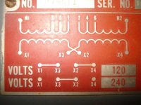
Many but not all of the 3-phase 208Y/120 transformer banks in my town are hooked up differently than the usual way of wiring wye transformer banks! Instead of the service neutral being hooked up to each of the 3 transformer taps opposite the tap each phase leg is connected to, some banks have the neutral coming off the center tap of each of the 3 transformers. In other words, the center taps of all 3 transformers are hooked together to make the system neutral.
My question is why are they wired like this?
My guess would be that only half of the secondary coil is being used because of rated voltage?
And these banks are definitely not delta connected secondaries! If they were, the system neutral would only be coming from the center tap of 1 transformer.
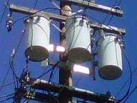
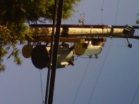
I will try to snap a pic next time I come across one.
Many but not all of the 3-phase 208Y/120 transformer banks in my town are hooked up differently than the usual way of wiring wye transformer banks! Instead of the service neutral being hooked up to each of the 3 transformer taps opposite the tap each phase leg is connected to, some banks have the neutral coming off the center tap of each of the 3 transformers. In other words, the center taps of all 3 transformers are hooked together to make the system neutral.
My question is why are they wired like this?
My guess would be that only half of the secondary coil is being used because of rated voltage?
And these banks are definitely not delta connected secondaries! If they were, the system neutral would only be coming from the center tap of 1 transformer.
I will try to snap a pic next time I come across one.