To avoid these ads, REGISTER NOW!

Question for the Sparkies - Interlock Backfeed Between Panels???

larry4406

Well-known member
Joined
Jan 27, 2006
Messages
19,575
Location
Northern Virginia
Question for the legit Sparkies (I am not one).

A friend asked me a question about his duplex which is under construction in Florida (prior was destroyed during hurricane). He owns both units (lives in one, rents adjacent unit).

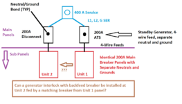
There is a SINGLE 400A service which serves both units; owner did not want to pay the separate meter few to have a meter on each unit. There is a shared laundry room, and the 200A main breaker panels for each unit are located there. The configuration is shown below in the graphic I made after talking with him this morning (hopefully its clear). I don't know if there are ground rods or a UFER.
1710881482338.png

Unit 1 (Owners residence) is fully backed up by an automatic generator to pick up all the loads in his residence. He would like to be able to run the mini-split and fridge in Unit 2 during loss of power events. The 200A main breaker panels are side by side with just a stud between them.

His electrician suggested installing a generator interlock with backfeed breaker at the Unit 2 panel (which is a sub panel), a piece of conduit with ******* between the panels, and a matching size breaker in the Unit 1 panel. I do not know the proposed breaker sizes nor the loads of the minisplit and the fridge.

As far as we know, the disconnect at Unit 2 only breaks L1 and L2 which we believe is same for the Generac ATS. The N-G bonds occur at the disconnect and in the ATS, with a common G at the meter can. Generator is 4-wire feed with separate N&G.

So - is his electrician's approach sound?
  • On Loss of Offsite Power, the ATS takes care of Unit 1 and separates it from the grid (L1 and L2 only to my knowledge).
  • Unit 2 is black on loss of offsite power. The disconnect is still enabled (pass thru). The owner would then rack off all of the breakers in Unit 2, flip the Unit 2 interlock taking it off the grid, enable the back feed breaker, then enable only its AC and fridge breakers.
  • Although the N-G bonds occur in two separate devices (disconnect and the ATS), electrically the seem to be the same to my untrained mind via the common G at the meter can.
Being the non-sparkie that I am, I suggested he just put Unit 2's AC, fridge, and maybe a main lighting circuit in the Unit 1 panel with appropriate labels and then he would not have to intervene (perhaps put the Unit 2 breakers at bottom of panel while keeping the Unit 1 breakers at the top of the panel). I expressed concern that an untrained user might try and rack too much load on in Unit 2 and what if no one is home at either unit? He would also need to undo this when power is restored which would not be needed if the cherry picked Unit 2 loads where put in the Unit 1 panel.

Thanks for your help.
 
Last edited:
To avoid these ads, REGISTER NOW!

dcg9381

Well-known member
Joined
Jun 20, 2018
Messages
11,925
Location
Austin, TX
If I follow, in "practicality" it would make senseto put an interlock on sub-panel #2 and a feed breaker from unit #1 (generator backup) associated with that interlock. That makes sense to me. Is that NEC legal? I have no ******** idea. But the idea seems right.

Being the non-sparkie that I am, I suggested he just put Unit 2's AC, fridge, and maybe a main lighting circuit in the Unit 1 panel with appropriate labels and then he would not have to intervene (perhaps put the Unit 2 breakers at bottom of panel while keeping the Unit 1 breakers at the top of the panel). I expressed concern that an untrained user might try and rack too much load on in Unit 2 and what if no one is home at either unit?
How is power paid for? I wouldn't want my neighbor AC load on my panel.
With modern power monitoring, you can monitor total power use and get actual use per unit for under $150 via a wifi device. One time fee.

Can you move stuff over to panel 1? The answer to that is typically via "load calculation" and my guess is if these are moderate condos and both have full 200A that the math will work when on grid power.

But it begs the question: Can the generator handle the load from both units? Because that's going to be a thing. A 20KW generator is only about 80A service feed. Two ACs starting at the same time may sink that generator. I have my ACs on "delay start" so that doesn't happen.
 
OP
L

larry4406

Well-known member
Joined
Jan 27, 2006
Messages
19,575
Location
Northern Virginia
If I follow, in "practicality" it would make senseto put an interlock on sub-panel #2 and a feed breaker from unit #1 (generator backup) associated with that interlock. That makes sense to me. Is that NEC legal? I have no ******** idea. But the idea seems right.


How is power paid for? I wouldn't want my neighbor AC load on my panel.
With modern power monitoring, you can monitor total power use and get actual use per unit for under $150 via a wifi device. One time fee.

Can you move stuff over to panel 1? The answer to that is typically via "load calculation" and my guess is if these are moderate condos and both have full 200A that the math will work when on grid power.

But it begs the question: Can the generator handle the load from both units? Because that's going to be a thing. A 20KW generator is only about 80A service feed. Two ACs starting at the same time may sink that generator. I have my ACs on "delay start" so that doesn't happen.
I believe he rents Unit 2 for days, couple weeks at a time, not long term. Like renting a beach house for a week where the rental fee is all in.

I advised him on the ability to net meter if he wanted.

The AC units are mini splits in both Units. I assume his sparkie has done the load calc to cover Unit 1 and sized it properly, not sure the head room it has. We talked about load shed via the integral dry contacts Generac provides as well as the line side load shed modules Generac offers.
 

eejack

Well-known member
Joined
May 18, 2021
Messages
166
Location
the garden state
The only issue is the grey matter safety. In other words, you 'have to know' how to do this or you can do this wrong and send power back to the grid.

( interestingly enough if you didn't open the unit #2 main you would put power on the grid which would do two things at once, choke the generator with potentially massive load and shut down the generator when it senses 'street' power on the top of the ATS so it might be a self correcting problem ).

It is all well and good if nothing ever goes wrong and no one ever makes a mistake.

I believe the suggestion above by dcg9381 about moving the critical loads to the unit one panel is the simplest and safest.
 

dcg9381

Well-known member
Joined
Jun 20, 2018
Messages
11,925
Location
Austin, TX
The only issue is the grey matter safety. In other words, you 'have to know' how to do this or you can do this wrong and send power back to the grid.
I disagree. The whole point of an interlock is that it's idiot proof, you cannot do it wrong. You are physically prevented from backfeeding. You can't reverse the electron streams.

The ATS handles the rest of it, it's either grid or generator.

If you can backfeed or loop it, better bet it's not NEC legal.

Maybe you mean the sparkie could do it wrong.. that's possible.
 

eejack

Well-known member
Joined
May 18, 2021
Messages
166
Location
the garden state
I disagree. The whole point of an interlock is that it's idiot proof, you cannot do it wrong. You are physically prevented from backfeeding. You can't reverse the electron streams.

The ATS handles the rest of it, it's either grid or generator.

If you can backfeed or loop it, better bet it's not NEC legal.

Maybe you mean the sparkie could do it wrong.. that's possible.

No, if you look at what he wants to do, he doesn't mention changing the main disconnect, he mentions turning off breakers. The 'interlock' is not on the main, but in a breaker on the panel proper.
Unit 2 is black on loss of offsite power. The disconnect is still enabled (pass thru). The owner would then rack off all of the breakers in Unit 2, flip the Unit 2 interlock taking it off the grid, enable the back feed breaker, then enable only its AC and fridge breakers.

Now, if he was putting in a transfer switch in lieu of the 200A disconnect, perhaps. But in that case, the expense of your method ( move a couple of circuits ) versus replace a 200A disconnect and install interlocking breakers, your method still comes out on top.

Perhaps I am misunderstanding what they are trying to do, but I can't imagine someone wasting all of that money and effort and making things manual and complicated and, since they have to decide how much load they may or may not want to add, not idiot proof.

Move a handful of circuits just seems more sensible.
 

dcg9381

Well-known member
Joined
Jun 20, 2018
Messages
11,925
Location
Austin, TX
No, if you look at what he wants to do, he doesn't mention changing the main disconnect, he mentions turning off breakers. The 'interlock' is not on the main, but in a breaker on the panel proper.
There is an ATS upstream of the panel 1. That can't backfeed. So panel 2 is either fed by grid or it's fed by interlock panel 1.
Let me know if I have it wrong.
Move a handful of circuits just seems more sensible.
Depending the orientation and length of wires may make sense, I agree.
I'm baffled by the concept of 2 residences with one meter and no one seems to care..
 

eejack

Well-known member
Joined
May 18, 2021
Messages
166
Location
the garden state
There is an ATS upstream of the panel 1. That can't backfeed. So panel 2 is either fed by grid or it's fed by interlock panel 1.
Let me know if I have it wrong.

Depending the orientation and length of wires may make sense, I agree.
I'm baffled by the concept of 2 residences with one meter and no one seems to care..

I am not sure if you are right or not actually. How does one put in an interlock and leave the main disconnect?

In my view you either have to replace the disconnect with a transfer switch ( interrupt the grid ) or you have the potential of mixing the grid and the generator. Throw in manually doing anything and that leads to

As far as the 2 residences one meter - options are the home owner is cheap, home owner is illegally renting the space out, home owner is including utilities in the rental, home owner is avoiding the 'house' panel ( third meter to provide for common area services ), all of the residents are members of the same family, home owner is providing shelter to the needy in the most efficient way possible. Humanity no longer baffles me sadly.
 
OP
L

larry4406

Well-known member
Joined
Jan 27, 2006
Messages
19,575
Location
Northern Virginia
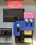
@eejack here is a typical generator interlock. Note how it’s either or - main breaker or the generator back feed. The presence of the disconnect is irrelevant other than it being where neutral and ground are bonded.

Both panels are main breaker panels as shown in the sketch. These act as disconnects in the panel.
1710888515558.jpeg
 
Last edited:

dcg9381

Well-known member
Joined
Jun 20, 2018
Messages
11,925
Location
Austin, TX
I am not sure if you are right or not actually. How does one put in an interlock and leave the main disconnect?
The interlock is in the sub-panel. This assumes there is a "main feed" in the subpanel - either a breaker or switch (in the sub panel) that gets thrown when the interlock gets switched. Not all sub-panels can accept interlocks. Without being able to lock out the grid, you don't have an interlock.

In my view you either have to replace the disconnect with a transfer switch ( interrupt the grid ) or you have the potential of mixing the grid and the generator.
We agree that any configuration of "mixing" grid and generator by accident is a violation of code and also makes you an idiot.

As far as the 2 residences one meter - options are the home owner is cheap, home owner is illegally renting the space out, home owner is including utilities in the rental, home owner is avoiding the 'house' panel ( third meter to provide for common area services ), all of the residents are members of the same family, home owner is providing shelter to the needy in the most efficient way possible. Humanity no longer baffles me sadly.
Sure. It's just so darn easy these days to stick a power meter on one or both sides. I have this identical setup pretty much, only my main is 320A and + solar. I monitor total power use with an app..
 
Last edited:
OP
L

larry4406

Well-known member
Joined
Jan 27, 2006
Messages
19,575
Location
Northern Virginia
This is all brand new construction.

The panels are main breaker panels as shown in the sketch.

I too questioned the single meter for two residences but that’s not relevant to the question. I don’t understand the why but just move on.

What if you had a single home, 400A service, 2 panels, only one of which was on a generator via an ATS but you wanted some loads on the other panel? Would you interlock it and self manage loads or just cherry pick circuits and move them to the generator panel?

What about the N-G question posed?
 

wyliesdiesels

Well-known member
Joined
Aug 14, 2012
Messages
20,073
Location
Modesto, CA
Question for the legit Sparkies (I am not one).

A friend asked me a question about his duplex which is under construction in Florida (prior was destroyed during hurricane). He owns both units (lives in one, rents adjacent unit).

There is a SINGLE 400A service which serves both units; owner did not want to pay the separate meter few to have a meter on each unit. There is a shared laundry room, and the 200A main breaker panels for each unit are located there. The configuration is shown below in the graphic I made after talking with him this morning (hopefully its clear). I don't know if there are ground rods or a UFER.

1710881482338.png
should work fine as long as the feeding breaker from unit 1's subpanel is interlocked with the 200a main breaker in unit 2's subpanel. he will need a 4-wire feed between the panels.
 
OP
L

larry4406

Well-known member
Joined
Jan 27, 2006
Messages
19,575
Location
Northern Virginia
Unit 1 & 2 subpanels are main breaker panels, so an interlock on unit 2 panel will work just fine with #2 being fed by #1. The interlock forces the disconnection of the main breaker in #2.
Thank you. This is my conclusion as well.

The N-G bonding at the ATS and disconnect should still be kosher, correct?
 

eejack

Well-known member
Joined
May 18, 2021
Messages
166
Location
the garden state
@eejack here is a typical generator interlock. Note how it’s either or - main breaker or the generator back feed. The presence of the disconnect is irrelevant other than it being where neutral and ground are bonded.
This is all brand new construction.

The panels are main breaker panels as shown in the sketch.

I too questioned the single meter for two residences but that’s not relevant to the question. I don’t understand the why but just move on.

What if you had a single home, 400A service, 2 panels, only one of which was on a generator via an ATS but you wanted some loads on the other panel? Would you interlock it and self manage loads or just cherry pick circuits and move them to the generator panel?

What about the N-G question posed?

That makes sense now.

The neutral and grounding would be fine assuming they are all bonded properly in the main service. This only works because there is only one service, only one meter.

Personally I would move the critical loads to one panel as it makes zero difference which panel a load is in. You mention they are a stud apart. Has to be cheaper that adding additional breakers/interlocks.
 
OP
L

larry4406

Well-known member
Joined
Jan 27, 2006
Messages
19,575
Location
Northern Virginia
should work fine as long as the feeding breaker from unit 1's subpanel is interlocked with the 200a main breaker in unit 2's subpanel. he will need a 4-wire feed between the panels.
Thank you.

Yes Unit 2 sub-panel would have the interlock and back feed breaker. Unit 1 matching supply breaker could be on all time I’m thinking (back feed breaker at Unit 2 sub panel controls). This covers L1 and L2.

Why would he need to tie the N an G bars between Panels 1 and 2 via a 4-wire feed? This is the question I have been struggling with. They are all still bonded at the ATS and Disconnect via the common G to the meter can? It is easy to do if needed.
 

dcg9381

Well-known member
Joined
Jun 20, 2018
Messages
11,925
Location
Austin, TX
What if you had a single home, 400A service, 2 panels, only one of which was on a generator via an ATS but you wanted some loads on the other panel? Would you interlock it and self manage loads or just cherry pick circuits and move them to the generator panel?
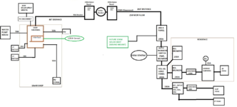
I have this configuration (below). What I did to solve it was put an interlock on panel 2 and a generator inlet. Panel 1 and generator are "automatic" and stuff just works. Panel 2, you have to walk down, flip the interlock, and fire up a 10KW generator by hand.

If this is a "vacation home" and we don't want food to go bad, I'd do it differently, I'd move the circuits over to the panel that is ATS protected.


1710889917195.png
 
OP
L

larry4406

Well-known member
Joined
Jan 27, 2006
Messages
19,575
Location
Northern Virginia
If this is a "vacation home" and we don't want food to go bad, I'd do it differently, I'd move the circuits over to the panel that is ATS protected.
My friend lives in MD but has this property on the coast of Florida. I don't know if he really winters there, plans to retire there, or what.

I also don't know if the occupants of Unit 2 are there when he is there, solo, etc. Friends, relatives, paying vacationers I have no clue.

I expressed my concern of him not being there, power is out, and the beach rental guest in Unit 2 screwing with things and perhaps overloading the generator. Thus my suggestion to cherry pick the Unit 2 critical loads and put them in the Unit 1 panel appropriately labeled (easier and automatic with no intervention).

The house is on stilts for flood reasons. His jurisdiction requires disconnects external to the home. Thus the disconnect for Unit 2. There is also a disconnect between the generator and the ATS (not shown) to address Unit 1. Although the ATS has an internal disconnect, you have to remove the cover for access. These disconnects are for emergency responders to kill the house locally from outside.
 

dcg9381

Well-known member
Joined
Jun 20, 2018
Messages
11,925
Location
Austin, TX
I expressed my concern of him not being there, power is out, and the beach rental guest in Unit 2 screwing with things and perhaps overloading the generator. Thus my suggestion to cherry pick the Unit 2 critical loads and put them in the Unit 1 panel appropriately labeled (easier and automatic with no intervention).
The generac "load shed" devices will cut their feeds for a specific amount of time if the generator frequency (RPM) or voltage drops. Just put the ACs on load shed (all of them) and you'll likely be fine. My issue with these is that both of mine have failed with 2-3 years, but it's a board problem and new boards have been redesigned.

The house is on stilts for flood reasons. His jurisdiction requires disconnects external to the home. Thus the disconnect for Unit 2. There is also a disconnect between the generator and the ATS (not shown) to address Unit 1. Although the ATS has an internal disconnect, you have to remove the cover for access. These disconnects are for emergency responders to kill the house locally from outside.
I get it, it's like solar. My ATS, you simply open the cover, but need a special tool to force disconnect. You could add "another" disconnect downstream to comply. Course the whole thing is ****** as you want all this above potential water level, but it has to be accessible via 1st responder.
 
To avoid these ads, REGISTER NOW!
OP
L

larry4406

Well-known member
Joined
Jan 27, 2006
Messages
19,575
Location
Northern Virginia
The N-G bond thing is bothering me and hoping @wyliesdiesels can educate me in a dumbed down manner so I can understand why he wants to connect the N bar in Panel 1 with N bar in Panel 2, and connect G bar in Panel 1 with G bar in Panel 2 - this is where my knowledge fails me.
 
Last edited:

wyliesdiesels

Well-known member
Joined
Aug 14, 2012
Messages
20,073
Location
Modesto, CA
The only issue is the grey matter safety. In other words, you 'have to know' how to do this or you can do this wrong and send power back to the grid.
not true with interlocked breakers.
( interestingly enough if you didn't open the unit #2 main you would put power on the grid which would do two things at once, choke the generator with potentially massive load and shut down the generator when it senses 'street' power on the top of the ATS so it might be a self correcting problem ).
with an interlock on the subpanel #2 main and the subpanel #1 feeding breaker, it would be impossible to have both closed at the same time.
It is all well and good if nothing ever goes wrong and no one ever makes a mistake.
how does one make a mistake with interlocked breakers? only one breaker can be closed at a time.

it seems you dont understand what an interlock is
I believe the suggestion above by dcg9381 about moving the critical loads to the unit one panel is the simplest and safest.
no actually thats more complicated than just installing an interlock. no need to move branch circuit wiring between panels
 

wyliesdiesels

Well-known member
Joined
Aug 14, 2012
Messages
20,073
Location
Modesto, CA
I am not sure if you are right or not actually. How does one put in an interlock and leave the main disconnect?

the 200a main disconnect that is just after the meter has no bearing on the interlocked main disconnect in the subpanel and the subpanel #1 feeding breaker in subpanel #2.
In my view you either have to replace the disconnect with a transfer switch ( interrupt the grid ) or you have the potential of mixing the grid and the generator. Throw in manually doing anything and that leads to
wrong again. the main disconnect in subpanel #2 and the #1 subpanel feeding breaker in subpanel #2 are interlocked. this means that subpanel #2 either gets power from the grid via the main disconnect above it or from subpanel #1 and the generator. theres no possibility here for the grid and the generator to be feeding subpanel #2 at the same time.
 

wyliesdiesels

Well-known member
Joined
Aug 14, 2012
Messages
20,073
Location
Modesto, CA
I just realized you said the ATS doesnt switch the neutral. but you also said the ATS has a bonded neutral. well you cant have the neutral bonded in 2 places. So either the ATS switches the neutral and you can have the neutral bonded in the ATS or the ATS doesnt switch the neutral and therefore should not have a bonded neutral in the ATS.
 
OP
L

larry4406

Well-known member
Joined
Jan 27, 2006
Messages
19,575
Location
Northern Virginia
I just realized you said the ATS doesnt switch the neutral. but you also said the ATS has a bonded neutral. well you cant have the neutral bonded in 2 places. So either the ATS switches the neutral and you can have the neutral bonded in the ATS or the ATS doesnt switch the neutral and therefore should not have a bonded neutral in the ATS.
Forgive me I’m not a sparkie.

To my knowledge, the ATS receives L1, L2, and G from the meter can. From here, it feeds sub panel Unit 1.

I understand that N&G are connected here inside the ATS and then the 4-wire feed goes to Unit 1 sub panel which has separate N&G bars.

I don’t have the ATS specs yet. I think, not certain, that the generator’s separate N&G all come into the ATS and connect to the same point (hence the black dot in my diagram).

I will circle back when I get more details on the Unit 2 disconnect and the ATS.

Thank you all.
 
Last edited:
OP
L

larry4406

Well-known member
Joined
Jan 27, 2006
Messages
19,575
Location
Northern Virginia
I just realized you said the ATS doesnt switch the neutral. but you also said the ATS has a bonded neutral. well you cant have the neutral bonded in 2 places. So either the ATS switches the neutral and you can have the neutral bonded in the ATS or the ATS doesnt switch the neutral and therefore should not have a bonded neutral in the ATS.

Forgive me I’m not a sparkie.

To my knowledge, the ATS receives L1, L2, and G from the meter can. From here, it feeds sub panel Unit 1.

I understand that N&G are connected here inside the ATS and then the 4-wire feed goes to Unit 1 sub panel which has separate N&G bars.

I don’t have the ATS specs yet. I think, not certain, that the generator’s separate N&G all come into the ATS and connect to the same point (hence the black dot in my diagram).

I will circle back when I get more details on the Unit 2 disconnect and the ATS.

Thank you all.
@wyliesdiesels

Some new information.

The automatic transfer switch for Unit 1 duplex 200A sub panel, is a Generac RXSW200A3. This is a Service Rated automatic transfer switch and serves as the main disconnect for Unit 1.

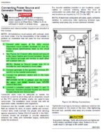
Here is an excerpt from the transfer switch manual. L1 and L2 from the meter can connect to terminals N1 and N2. The manual makes references to jumpers A and B, but "B" is not depicted; I can't explain this. The manual is quite clear to connect the generator's neutral to the lower neutral lug and never remove the jumper wire (described as B but shown as A) which connects the upper and lower bars.

Because Jumper A remains in place, I believe the neutrals and grounds are all connected together here in this device. I had previously used the term "bond" for this junction (and my black dot in my graphic) so I hope I have used the term properly.

The generator wiring is 4-wire feed from the generator, connected to the transfer switch per the manual, and at the generator the N&G are separate.

I am still waiting on details for the Unit 2 disconnect. I believe it to be a service rated disconnect. I have to believe it is only breaking L1 and L2 with an internal lug/bar where the utility neutral lands and then the 4-wire feed from the Unit 2 main breaker subpanel has the N&G connected to the utility neutral. Unit 2 200A main breaker sub panel then has separate N&G bars.

1710959091858.png

I BELIEVE THE SERVICE AND MAIN PANELS ARE LIKE THIS. This example is a prior home I was involved with. 400A service, two 200A sub panels, only one of the 200A panels backed up by a generator via the ATS. This picture was taken before the feeders to the sub panels were run and before the power company tied in the meter can. The ground wire shown in the left panel (ATS) going thru the conduct is connected to the UFER ground in the home. You can see the green jumper "A" is in position bonding (I hope right use of term) the neutral and ground.
1710959983272.png

I will circle back when I get more details. My friend is supposed to be on site next week and he will remove the panel covers and take pictures of what he has, verify device part numbers, etc.
 

wyliesdiesels

Well-known member
Joined
Aug 14, 2012
Messages
20,073
Location
Modesto, CA
ok so the ATS is the disconnect for unit 1 and there is no disconnect ahead of it?

it doesnt look like it switches the neutral.
 

mm08822

Well-known member
Joined
Jan 13, 2012
Messages
6,053
Location
NJ
This is all brand new construction.

The panels are main breaker panels as shown in the sketch.

I too questioned the single meter for two residences but that’s not relevant to the question. I don’t understand the why but just move on.

What if you had a single home, 400A service, 2 panels, only one of which was on a generator via an ATS but you wanted some loads on the other panel? Would you interlock it and self manage loads or just cherry pick circuits and move them to the generator panel?

What about the N-G question posed?
The N-G question is still an issue. When the tie breaker from panel 1 is closed and the interlocked cb in panel 2 is closed (& main cb open), the neutral current required for panel 2 will split into 3 paths:
  • Neutral Path 1 - from path #2's nuetral up into the 200a disconnect enclosure's neutral, into the meter, and back into the transfer switch's neutral bar.
  • Neutral Path 2 through the neutral of the tie breaker wiring between panel #1 and panel #2.
  • Ground Path 3 - neutral path 1 current will further split at disconnect #2's bonding screw, through the enclosure/conduit ******* and recombine at the xfer switch's bonded neutral bar. (This would create a shock hazard.)

This is the same situation as created in this thread: https://www.garagejournal.com/forum...outlets-two-main-panels.528743/#post-10548412

Best way to have accomplished this (having only one meter) would have been to use a single 400a ATS immediately after meter. There would be only one bonding screw and it would be in the xfer sw.

An ATS with a switched neutral would still not work b/c of the 2 bonding screws in seperate locations.
 

dcg9381

Well-known member
Joined
Jun 20, 2018
Messages
11,925
Location
Austin, TX
Best way to have accomplished this (having only one meter) would have been to use a single 400a ATS immediately after meter. There would be only one bonding screw and it would be in the xfer sw.
Now we are into a swing of 300% for a 400A ATS over a 200A ATS.
Move the loads. That's where I'm at. The interlock is manual anyway.
 

mm08822

Well-known member
Joined
Jan 13, 2012
Messages
6,053
Location
NJ
Now we are into a swing of 300% for a 400A ATS over a 200A ATS.
Move the loads. That's where I'm at. The interlock is manual anyway.
The point was what does it take to make the current service architecture code compliant and safe vs. "Is that NEC legal? I have no ******** idea." Of course plugging a few cb's into a different panel is easiest.........but that contradicts the 2 service expectation.

The interlock being manual means nothing.

Pre-planning goes a long way versus screwing it all up at the last minute and making a safety issue. Probably don't even need a 400a service, but if required, the incremental cost of a 400A ats is meaningless when rebuilding a duplex.
 
Last edited:

Tundra1

Well-known member
Joined
Sep 3, 2023
Messages
202
Seems unusual for residential but how's this different than an industrial main-tie-main distribution? each sub-panel contains a main breaker with an upstream feed along with an interlocked tie breaker.
 

mm08822

Well-known member
Joined
Jan 13, 2012
Messages
6,053
Location
NJ
Seems unusual for residential but how's this different than an industrial main-tie-main distribution? each sub-panel contains a main breaker with an upstream feed along with an interlocked tie breaker.
The only way to answer that is with a one-line or possibly needing a 3 line diagram as the devil is in the details.
  • Panels could be 3 pole, 4 wire (delta only) not needing to be concerned with neutral paths.
  • Where neutral bonding occurs is also relevant.
  • CBs and xfer switches could be 4 pole. Rack mounted breakers can have a lot of features.
  • Protective relaying and kirk key type interlocks provide a world of difference to that of a residential low end system.
No single answer will apply to all industrial distribution systems.
 
OP
L

larry4406

Well-known member
Joined
Jan 27, 2006
Messages
19,575
Location
Northern Virginia
The N-G question is still an issue. When the tie breaker from panel 1 is closed and the interlocked cb in panel 2 is closed (& main cb open), the neutral current required for panel 2 will split into 3 paths:
  • Neutral Path 1 - from path #2's nuetral up into the 200a disconnect enclosure's neutral, into the meter, and back into the transfer switch's neutral bar.
  • Neutral Path 2 through the neutral of the tie breaker wiring between panel #1 and panel #2.
  • Ground Path 3 - neutral path 1 current will further split at disconnect #2's bonding screw, through the enclosure/conduit ******* and recombine at the xfer switch's bonded neutral bar. (This would create a shock hazard.)

This is the same situation as created in this thread: https://www.garagejournal.com/forum...outlets-two-main-panels.528743/#post-10548412

Best way to have accomplished this (having only one meter) would have been to use a single 400a ATS immediately after meter. There would be only one bonding screw and it would be in the xfer sw.

An ATS with a switched neutral would still not work b/c of the 2 bonding screws in seperate locations.
@mm08822 - thanks for noodling this out with me!

As I said, I am not a sparky but my gut feel was something was wrong with this N-G setup if the interlock were done at Panel 2. Your explanation makes sense. The option of a 400A ATS is long gone.

Further educate me please.
  • Neutral Path 1 - these conductors I assume are sized properly for 200A during normal grid power. The back feed breakers I assume would be at most 50A, and the generator output breaker is at most 100A. Wouldn't this mean this path is adequate?
  • Neutral Path 2 - This 4-wire conductor would be sized to the assumed back feed breaker of 50A. The N&G in this conductor would connect N1 to N2 and G1 to G2 (ie - jumper the bars together). Wouldn't this mean that this path is also adequate?
  • Ground Path 3 - You got me here at the shock hazard statement. Although I don't fully understand the why, I think this is the deal breaker.
I will update with more details next week when my friend is on site. I don't expect things will change from this point. I will advise him that the best option at this point is to cherry pick the Unit 2 loads and put them in the Unit 1 panel, only after confirming the generator has adequate head room. If necessary, he can load shed some loads making the Unit 2 loads sacrificial.
 
Last edited:

dcg9381

Well-known member
Joined
Jun 20, 2018
Messages
11,925
Location
Austin, TX
The point was what does it take to make the current service architecture code compliant and safe vs. "Is that NEC legal? I have no ******** idea." Of course plugging a few cb's into a different panel is easiest.........but that contradicts the 2 service expectation.
I think you're sorting out the details with real sparkys. It's the N switching that's tricky to me, which is why I said "no idea" on NEC legal.. I'm largely commenting on the functionality side of it. I have a similar setup (add solar). So I do have "some idea" - there are just people here that do this for a living.

The interlock being manual means nothing.
Depends on your use case. If the condos are vacation or will be abandoned (say during a hurricane) and you don't want to come back to a mess of spoiled food/melted ice, it might matter. The ATS condo "just works".
 

mm08822

Well-known member
Joined
Jan 13, 2012
Messages
6,053
Location
NJ
@mm08822 - thanks for noodling this out with me!

As I said, I am not a sparky but my gut feel was something was wrong with this N-G setup if the interlock were done at Panel 2. Your explanation makes sense. The option of a 400A ATS is long gone.

Further educate me please.
  • Neutral Path 1 - these conductors I assume are sized properly for 200A during normal grid power. The back feed breakers I assume would be at most 50A, and the generator output breaker is at most 100A. Wouldn't this mean this path is adequate? (1)
  • Neutral Path 2 - This 4-wire conductor would be sized to the assumed back feed breaker of 50A. The N&G in this conductor would connect N1 to N2 and G1 to G2 (ie - jumper the bars together). Wouldn't this mean that this path is also adequate? (2)
  • Ground Path 3 - You got me here at the shock hazard statement. Although I don't fully understand the why, I think this is the deal breaker. (3)
I will update with more details next week when my friend is on site. I don't expect things will change from this point. I will advise him that the best option at this point is to cherry pick the Unit 2 loads and put them in the Unit 1 panel, only after confirming the generator has adequate head room. If necessary, he can load shed some loads making the Unit 2 loads sacrificial.
1. Assuming conductors are sized per cb rating, overload is a non-issue. The problem is this current path is not a singular current path run with the transfer circuit conductors. Code requires all ccc of a circuit to be in same cable/conduit, etc.
2. Assuming conductors are sized per transfer circuit cb rating, this neutral path is the correct path. The problem is, neutral current splits off of the intended path due to #1 above.
3. This is the bigger safety problem.......current traveling on the enclosure, conduit surfaces. With current flow, there is a voltage gradient created and can provide a shock hazard if a person were to touch these parts and another grounded item at a different potential. If the bonding screws in disc 1, meter pan and ats didn't exist, the problem would be eliminated. Problem is they are needed when the grid is running.
 

mm08822

Well-known member
Joined
Jan 13, 2012
Messages
6,053
Location
NJ
I think you're sorting out the details with real sparkys. It's the N switching that's tricky to me, which is why I said "no idea" on NEC legal.. I'm largely commenting on the functionality side of it. I have a similar setup (add solar). So I do have "some idea" - there are just people here that do this for a living.


Depends on your use case. If the condos are vacation or will be abandoned (say during a hurricane) and you don't want to come back to a mess of spoiled food/melted ice, it might matter. The ATS condo "just works".
Having some idea to make it just work vs. making it safe & code compliant can be very different.
 

wyliesdiesels

Well-known member
Joined
Aug 14, 2012
Messages
20,073
Location
Modesto, CA
yes the neutral current flow is an issue especially since the ATS isnt switching the neutral and you have another pathway thru panel #2 disconnect.
 

Al G

Well-known member
Joined
Jan 5, 2015
Messages
340
Location
Arizona
Since this is all on one meter why does it have to be any different than a typical 400 amp service with two 200 amp panels? I had a generator installed in my last house. I don't know the specifics of what components they used but the end result was all the critical circuits were moved to panel 1 and it was powered by the generator. If capacity was available from the generator power was also available to panel 2. There was just no guarantee on how much of panel 2 could be used when on generator power. All switches and disconnects were automatic with standard Generac components. Absolutely no manual intervention during a power outage.
 
To avoid these ads, REGISTER NOW!
Top Bottom