To avoid these ads, REGISTER NOW!

Quincy 325 Rebuild Thread

kunkernator

Well-known member
Joined
Sep 27, 2012
Messages
2,438
Location
US of A
In reference to my original thread:
Calling Quincy 325 Experts

Strouty; I have not forgot about you :D

I have been real busy throughout the past few months and have not had a chance to post, although I have done major work on my projects. The following posts will be of my Quincy 325 ROC 106 rebuild. I will keep a post following this one with general useful information, torque specs, etc...

Understand that it takes a long time to compile all this information I am about to upload, so bear with me.

Feel free to comment, expand, and share :rocker:

If I provided any incorrect information, please let me know and I will fix it. If there is information that you feel needs to be included in the first post, let me know.
 
Last edited:
To avoid these ads, REGISTER NOW!
OP
K

kunkernator

Well-known member
Joined
Sep 27, 2012
Messages
2,438
Location
US of A
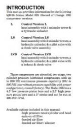
First, I would like to go over the basic scope of a Quincy 325 air compressor, and what options there are.

The Quincy 325 air compressor is considered by some the "Rolls Royce" of air compressors, they are capable of compressing up to 500PSI with optional equipment, but for the home shop user, and for the purpose of this thread, we will stick with the version that is rated for 200PSI or below.


RECORD OF CHANGE
(What version compressor do I have?)


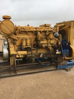
Quincy uses a system called "Record of Change" or ROC for short, which is the identifier on your compressor to determine what version you have, what updates have been performed, and assists you in ordering the correct parts. In terms of rebuilds, ROC 1-9 share common parts, while 9 and up share common parts: I.E. If you were to order a rebuild kit, there are essentially two available, one for ROC 1-9, and one for ROC 9-UP. Quincy is currently up to ROC 107 if I recall. The ROC number can be found in the upper right corner of the data plate (I say upper right corner, because most data plates have their words worn off, but the compressor model and ROC are stamped in).

It should be noted that there are reports of compressors off of Quincy packaged units (compressor, tank, motor), not having an ID plate, as the tank has one for the unit on it.

See below image for ID of ROC and compressor model number.
attachment.php


CONTROL VERSION
(Why does my compressor have two towers on top,
but others have one?)


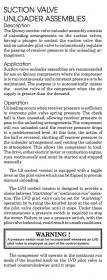
First off, the "Towers" on top are called unloaders. When air pressure is applied thru the supply line to the unloaders, it pushes on a diaphragm, which then pushes on the intake valve of either the high pressure or low pressure side of the compressor (or both if you have two towers), and essentially takes the 'load' off the compressor by holding the intake valves open constantly, thus not producing pressure.

The air is supplied to these unloaders when one of two conditions are met, low oil pressure (thus unloading the compressor to prevent more extensive damage), or pilot valve unloading (a pressure is set on the pilot valve, and when the receiver or air tank reaches said pressure, the compressor is unloaded). The different control groups Quincy offers combines one or both of these features depending on the application.

There are three control group styles that could be shipped on your Quincy 325. L, LS, and LVD.

TO ID YOUR CONTROL VERSION: L has one unloader tower, LS and LVD both have two towers, LS uses a toggle lever on the pilot valve, while LVD uses a knurled thumb screw.

Control version L

The control version L only has a hydraulic unloader, and one unloader tower. This would be designed for a start/stop application. When your air tank reaches it's desired pressure, and the motor is electronically shut off via a pressure switch, the compressor then stops spinning. Due to the loss of motion, no oil pressure is being supplied, so the hydraulic unloader opens up and unloads the compressor. The goal of this is to enable the compressor to start back up in an "unloaded" state, not already having pressure in the cylinders. This puts less wear on your motor, and compressor.

Control version LS

The control version LS has a hydraulic unloader, a three way check valve, and a pilot valve. This version also has two unloader towers. This version is designed for continuous run applications only. It maintains the features of the L version as to when there is a loss of oil pressure, it automatically unloads, but it adds a pilot valve, which is adjustable to a specific set point. When this set point is achieved, both unloaders are fed air pressure, so the compressor can freewheel and not create any more pressure, but stay running. This is mainly seen on units paired with a gas or diesel engine. It also has a toggle to allow you to bypass the unloader and "manually unload" the compressor (will not maintain pressure with the toggle, it will not create pressure until the toggle is re-enabled).

Control version LVD

This control version combines the features of the L and LS control versions. LVD enables you to use your compressor in a "start/stop" application, or a continuous run application, without changing any components. This version functions identically to the LS version, except instead of a toggle on the pilot valve, this version has a screw. With the screw turned clockwise, it allows for a start/stop application (functioning as control version L), with the screw turned all the way counter clockwise, it allows for a continuous run application (functioning as control version LS). The application for this version is generally on an electric driven compressor, which could allow for continuous run if more air volume is desired. For example, if you are sand blasting (a very air intensive job), the control can be switched to continuous run, thus allowing the compressor to run constant, and unload when max pressure is obtained. This function will keep you air pressure closest to max.

Below are a couple of excerpts out of Quincy's manual, explaining the control versions further.

attachment.php

attachment.php


OTHER FEATURES

There are other changes in Quincy 325 compressors, and the offerings, below is a brief overview of some of them.

Cooling fins
Some Quincy compressors have multiple vertical cooling fins, while some have less, horizontal ones. Generally speaking, the horizontal finned compressors are newer, or later models. This is also combined with the intercooler being pipe-threaded on the later models. The early models have a flanged intercooler. While some models have different style intercoolers, I have found that most "overhaul" gasket kits provide extra gaskets as to cover the different designs.
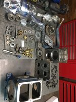
Oil filter
Quincy 325 compressors can be found with or without an oil filter housing. While all other parts of the compressor appear to be the same, the main difference is the front bearing carrier. This part does not allow for an oil filter housing, or filter to be installed in most cases. In order to convert your "non filtered" unit to a filtered one, this carrier must be changed. ALL 325 compressors are pressure lubricated, wether it has a filter or not, the filter just adds longevity to the compressor and oil change intervals. To my knowledge, all new 325 units ship with filter housings.

Air filter
There are many air filter options, and Quincy even offers different ones. There are hooded air filter housings, where the air is sucked from underneath the "umbrella", and there are open ones. This is pretty self explanatory, if your compressor is open to the elements, use a hooded housing, if it is indoors, you could use either. There are also paper or cotton mesh filters available. The paper filters can ONLY be used for start/stop applications, and they are not reusable. The cotton mesh filters are reusable (similar to a K&N filter), and can be used in a continuous run application. Continuous run applications create back pressure thru the intake while unloaded and running, so this would destroy a paper filter fairly quickly, as the cotton mesh ones can stand up to the abuse.

QUICK REFERENCE

Below are commonly needed tidbits of information.

Find your service manual:
https://www.quincycompressor.com/resources/support/

Torque Specs (the ones that are important):
These are for a later model compressor, most should be similar, but refer to your ROC specific manual for exact specs.

Flywheel Sheave (pinch) bolts: 90 ft lbs
Rod nuts: 35 ft lbs
Head bolts: 50 ft lbs
Valve cover bolts: 50 ft lbs
Valve jam bolt/nut: 60 ft lbs for bolt, 50 ft lbs for jam nut
Unloader valve jam "screw": 70 ft lbs
Unloader tower: 75 ft lbs

Lubrication recommendations:
Obviously Quincy recommends to use their brand, but generally speaking, 10, 20, or 30 weight NON DETERGENT engine oil is what is used. I run 30 weight all year. Lighter viscosities are good for cold climate/outdoor use.

Lubrication capacity:
Current models call for 1 quart and 16 oz without filter, and add 10 oz for use with filter. Check your ROC specific manual for exact measurements, but they should be fairly close.

YOUR FLYWHEEL IS 16'' diameter. This can be used to help calculate what size pulley you would like to run on the motor. Remember, all 325 compressors must run at least 400 RPM, but no greater than 900 RPM. You have to decide how to pair your compressor with what motor, lower horse motors cannot run the compressor at high RPMs combined with high pressures. A 5 HP motor should be sufficient to run the compressor at near 900 RPM and achieving a max pressure of 175 PSI. To calculate your needed pulley, use this link:
https://www.blocklayer.com/pulley-belteng.aspx

For parts, you can find them used, new, OEM, or aftermarket. For gasket kits for general rebuilds, I recommend Pacific Air Compressors. They have an eBay store as well, but their service is unbeatable. I have had issues and they have taken care of me.
https://www.pacificaircompressors.com/shop/products/
 

Attachments

  • Screen Shot 2018-01-08 at 6.36.59 PM.jpg
    Screen Shot 2018-01-08 at 6.36.59 PM.jpg
    13.6 KB · Views: 880
  • Screen Shot 2018-01-08 at 6.23.17 PM.jpg
    Screen Shot 2018-01-08 at 6.23.17 PM.jpg
    11.5 KB · Views: 852
  • Screen Shot 2018-01-08 at 7.02.03 PM.jpg
    Screen Shot 2018-01-08 at 7.02.03 PM.jpg
    9.9 KB · Views: 833
Last edited:
OP
K

kunkernator

Well-known member
Joined
Sep 27, 2012
Messages
2,438
Location
US of A
Lets start off my rebuild! Like I said, I am complete with it at this time (1/9/2018), and am awaiting the motor/parts to finish the tank....


This started, as I was in need of a new compressor for the home shop. My boss was very generous (rather owner of the company I work for), and let me grab one of MANY compressors off of a worn out engine in the yard. I actually do not have a picture of the engine I got mine from, but this was a "sister" engine that is configured the same way, but with an older 325 (note vertical fins).


attachment.php


For those of you wondering, that is a Caterpillar D342... I am in the engine rebuild field, I overhaul and repair industrial and generator set engines of all makes and models, but currently almost exclusively Caterpillar.


Now to MY compressor, It is a 325 ROC 106, minus a couple of copper lines, everything is there!


attachment.php


attachment.php


attachment.php


attachment.php


Right off the bat, I know I will be getting a new air filter housing, as this one does not belong on this compressor, and is in very poor shape.


Unfortunately, I have no pictures of disassembly, as it goes fairly quickly, and is very straight forward.

Lets take a look now at how I F’ed up. In order to pull the pulley off the compressor, you must loosen or remove the sheave (pinch) bolts, then drive two chisels or wedges on either side of the crankshaft. Then, with a T-bar puller, grab the pulley and push off the crankshaft. Where i screwed up is that a dropped the pulley.... it is VERY heavy, and you should have a friend help you with this part of the disassembly. Anyhow. I dropped the pulley and chipped it...

33c8a7d832f2ee5359934167e53f5a0b.jpg

And here is a little lesson on how to braze cast iron. Bevel the edges, but leave the rough casting, this helps to give the brass something to stick to. Remember, you are not welding or fusing the metal, but rather gluing it.

39c9afe2cc6ec56fa3e601a7dcdbbeb7.jpg

After you are prepped, preheat the cast iron part with a rosebud or your brazing torch. Dont get it red hot, but be generous. Afterwards, you want to braze the piece in place. Then let the piece cool at room temperature. Do not get in a rush and quench it, it WILL crack.

0cfbec4cbc00f492f0fda1125085cbfa.jpg

After some grinding....

619652202d4b98f16f4072e769b18058.jpg

And then some JB Weld to fill the gaps.

f4344c86e2263804577fec4e20838f14.jpg

And sanded down ready for paint.

3dc89ef20e5986e18be3d0bae6374b41.jpg

You will have to trust me when i say you CANNOT find this repair under the paint. Came out wonderful!

I did take a couple pictures of the crankshaft during disassembly. It is important to see that there are tapered roller bearings on the shaft. While there may be many ways to remove these, the CORRECT way is to use a bearing splitter. Both cones are on the crankshaft, the flywheel side cup is easy to remove from the crankcase, but the front bearing carrier cup is in a blind hole. I used an internal 3 jaw puller combined with a slide hammer to remove this.

Bearing splitter used: https://www.amazon.com/OTC-4518-Stinger-Bar-Type-Separator/dp/B0002SR47M/ref=sr_1_1?ie=UTF8&qid=1515556206&sr=8-1&keywords=otc+bearing+splitter

Slide hammer used (comes with 3 jaw puller): https://www.amazon.com/OTC-4579-9-Way-Hammer-Puller/dp/B0015DMNIS/ref=sr_1_1?s=automotive&ie=UTF8&qid=1515556243&sr=1-1&keywords=otc+4579+9-way+slide+hammer+puller+set

Old bearings off:

95384d84ff002ce1fd3e234be6fab83a.jpg

New bearings on:

8afee33409f8b9c887b6a4c8c2280fa4.jpg

To ease in removal you can heat the bearings or cut the cages off. To ease in install, you can choose to heat the new bearings up in an oven to slightly expand them, as i did. Just remember to keep the new bearings under 300 deg F, to prevent deterioration of the metals. Then use an appropriate sized driver, or socket, and tap them on.

On the crankshaft remember to reinstall the oil plugs if you remove them (i recommend to, in order to clean the galleys). Also clean the sealing surface of the rear seal, and inspect the journals for any damage.


To end tonights post, i am going to end with a teaser. Here are all of the parts prepped for reassembly. I will go in to more detail on the prep work involved and what i used.

81e232fb0df9ac8d5e53693a11c5faf1.jpg
 

Attachments

  • IMG_2942.jpg
    IMG_2942.jpg
    138.7 KB · Views: 742
  • IMG_2943.jpg
    IMG_2943.jpg
    137 KB · Views: 735
  • IMG_2944.jpg
    IMG_2944.jpg
    145.9 KB · Views: 741
  • IMG_2941.jpg
    IMG_2941.jpg
    145.8 KB · Views: 750
  • IMG_2891.jpg
    IMG_2891.jpg
    146.5 KB · Views: 762
  • 81e232fb0df9ac8d5e53693a11c5faf1.jpg
    81e232fb0df9ac8d5e53693a11c5faf1.jpg
    312.8 KB · Views: 10
  • 8afee33409f8b9c887b6a4c8c2280fa4.jpg
    8afee33409f8b9c887b6a4c8c2280fa4.jpg
    452.4 KB · Views: 7
  • 95384d84ff002ce1fd3e234be6fab83a.jpg
    95384d84ff002ce1fd3e234be6fab83a.jpg
    235.1 KB · Views: 8
  • 3dc89ef20e5986e18be3d0bae6374b41.jpg
    3dc89ef20e5986e18be3d0bae6374b41.jpg
    243.9 KB · Views: 7
  • f4344c86e2263804577fec4e20838f14.jpg
    f4344c86e2263804577fec4e20838f14.jpg
    243.1 KB · Views: 7
  • 619652202d4b98f16f4072e769b18058.jpg
    619652202d4b98f16f4072e769b18058.jpg
    217.2 KB · Views: 7
  • 0cfbec4cbc00f492f0fda1125085cbfa.jpg
    0cfbec4cbc00f492f0fda1125085cbfa.jpg
    261.7 KB · Views: 7
  • 39c9afe2cc6ec56fa3e601a7dcdbbeb7.jpg
    39c9afe2cc6ec56fa3e601a7dcdbbeb7.jpg
    465.2 KB · Views: 7
  • 33c8a7d832f2ee5359934167e53f5a0b.jpg
    33c8a7d832f2ee5359934167e53f5a0b.jpg
    515.2 KB · Views: 7
Last edited:

The Tool Tyrant

ALLIANCE MEMBER
Joined
Dec 19, 2011
Messages
2,181
Location
Bonita, Ca. (San Diego)
Great info Kunk! I too am a huge fan (have four) of the QR25-325 pump.

Regarding the Model /ROC tag, I recently found and purchased a VERY lightly (almost brand new) used Quincy model BM325VT 80 off of e-bay. When I received it, I noticed that there was no tag on the pump and it didn't look as one was ever installed. :headscrat I phoned Quincy and spoke with CS and the gentleman stated that they no longer include the tag...really? He stated they can pull all the pump info from the main info tag. I am still doubting that his info is correct, as once the pump is pulled from the tank, you would have lost any information associated with the pump. :dunno:
 

Fluxion

Well-known member
Joined
Apr 9, 2013
Messages
171
Location
Topeka. Kansas
Good stuff kunkernator! I have a 325 that i have been using for about 4 years with a knock that goes away after pressure builds to over 40 psi or so. I have been meaning to tear it down and rebuild it but never found the time. This thread may just get me to finally do that and I am looking forward to your build.
 

The Tool Tyrant

ALLIANCE MEMBER
Joined
Dec 19, 2011
Messages
2,181
Location
Bonita, Ca. (San Diego)
Good stuff kunkernator! I have a 325 that i have been using for about 4 years with a knock that goes away after pressure builds to over 40 psi or so. I have been meaning to tear it down and rebuild it but never found the time. This thread may just get me to finally do that and I am looking forward to your build.

Hey Flux, watch and listen to the first 45 seconds of this video...


Fluxion

Well-known member
Joined
Apr 9, 2013
Messages
171
Location
Topeka. Kansas
Hey Flux, watch and listen to the first 45 seconds of this video...


I love this place! You guys are always good for advice and links like yours. :beer:
Thanks for the link, I have seen the video and that's exactly what mine sounds like. Actually I think in my original thread somebody posted a link to that same rotarycomptech's video.

I was wrong about mine, I thought it quit knocking at 40 psi. I looked up a YouTube video I posted on here when I first got the compressor running back in 2014 and it quits knocking at about 20 psi.

Here's a link to my video:
 
OP
K

kunkernator

Well-known member
Joined
Sep 27, 2012
Messages
2,438
Location
US of A
Great info Kunk! I too am a huge fan (have four) of the QR25-325 pump.

Regarding the Model /ROC tag, I recently found and purchased a VERY lightly (almost brand new) used Quincy model BM325VT 80 off of e-bay. When I received it, I noticed that there was no tag on the pump and it didn't look as one was ever installed. :headscrat I phoned Quincy and spoke with CS and the gentleman stated that they no longer include the tag...really? He stated they can pull all the pump info from the main info tag. I am still doubting that his info is correct, as once the pump is pulled from the tank, you would have lost any information associated with the pump. :dunno:

Good to know! Quincy sells the 325s as a packaged deal, and just as a pump. I will add this information to the top post.

Good stuff kunkernator! I have a 325 that i have been using for about 4 years with a knock that goes away after pressure builds to over 40 psi or so. I have been meaning to tear it down and rebuild it but never found the time. This thread may just get me to finally do that and I am looking forward to your build.

Check out the top posts, as I am adding more information this evening!:beer:
 

blazemaster83

Well-known member
Joined
Oct 8, 2009
Messages
604
Location
Lacey, Wa.
Nice 325! I have a 390 that had been waiting on a rebuild as well. Mine does not have a spin on oil filter and is setup for control version LVD. Can't wait to see the finished product.
 
To avoid these ads, REGISTER NOW!
OP
K

kunkernator

Well-known member
Joined
Sep 27, 2012
Messages
2,438
Location
US of A
There will be more updates soon. Been real busy as i am in the process of buying a house. Stay tuned!


Sent from my iPhone using Tapatalk
 

Geezershop

Well-known member
Joined
Nov 21, 2013
Messages
89
Location
Lubbock, Texas
I bought my Quincy 325 30 years ago. It is probably from the 50s and sits on upright 80 gallon tank. It has been bulletproof all these years even though it runs outdoors. Now the unloader tower seems to be stuck open so it won't pump. I have seen replacement diaphragms and I wonder what is involved in rebuilding this part.
 

250

Well-known member
Joined
Oct 16, 2014
Messages
537
Location
West of the Sierras
Could be as simple as a replacement diaphragm, could be something has finally corroded enough to stick. Unbolt the top place and have a look. You shouldn't need to take the tower off to unpack and rejuvenate. Also, go to the Quincy site and fine the appropriate parts diagrams and rebuild walk though for your ROC. They're free and quite detailed.
 

Avispex

Active member
Joined
Jul 21, 2012
Messages
38
There will be more updates soon. Been real busy as i am in the process of buying a house. Stay tuned!


Sent from my iPhone using Tapatalk

This thread was just too good to go down in flames, but since the author hasn't been on in several months, the chance of getting the remaining updates may be slim....

Andy
 

seniorasi

New member
Joined
Jun 17, 2020
Messages
1
Location
memphis
Quincy 325L with hydraulic unloader. ROC: 100. The compressor is not unloading. If I remove the line from the tank side of the pilot valve I get air. Removing the line from the other side I get nothing. Rebuild or replace the pilot valve? I bought the kit but it looks like a number of precision parts and then how do I set the pressure in the pilot valve? I'll be happy to replace the entire valve if you feel it a better move.
 

TonyJ

Well-known member
Joined
Sep 10, 2019
Messages
384
Location
West Virginia
Quincy 325L with hydraulic unloader. ROC: 100. The compressor is not unloading. If I remove the line from the tank side of the pilot valve I get air. Removing the line from the other side I get nothing. Rebuild or replace the pilot valve? I bought the kit but it looks like a number of precision parts and then how do I set the pressure in the pilot valve? I'll be happy to replace the entire valve if you feel it a better move.


The pilot valve pressure is set by the spring that’s inside of it. Different color springs for different pilot pressures. There is also a screen made of felt inside the hydraulic unloader on both sides ( in and out ) that could be stopped up and not allowing air to pass thru and keeping the unloaders from working


Tony
 
To avoid these ads, REGISTER NOW!
Top Bottom