To avoid these ads, REGISTER NOW!

Quincy Pluming Help

InjectorService

Well-known member
Joined
Dec 11, 2019
Messages
266
Location
Canada
I need some help on my Quincy I just bought. I've had others, but they all had much simpler plumbing.

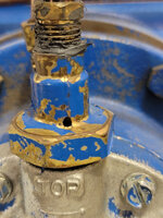
I fired this one up, and it seems to be letting pressure straight from the tank out of this hole. Anyone know what to make of that?

20230912-205113.jpg

20230912-205316.jpg
 
To avoid these ads, REGISTER NOW!

TeenagerThatLikesFloorjac

Well-known member
Joined
Dec 30, 2020
Messages
82
Location
QC
What pump is this and ROC? There is usually a tag on the crankcase with that info.

That hole doesn't seem right. A Quincy pressure lubed pump wouldn't just vent to atmosphere, it redirects it back to the head. More pictures would help. I believe that copper line on the right of the cylinders leading to the left of the head is the real crankcase breather.

It's a 2 stage pump (intercooler) pressure lubed and looks kind of small. If i had to guess it's a Quincy 310? Relatively new model too since it has a screw on filter.

You can find the manual for you pump on the quincy website:
If you go to quincycompressor.com
>Resources
>Literature library
and search your pump "QR 310" you'll find what they have posted. Filter by "list" helps too.
------------------------------*if i am right*-----------------------------
 
Last edited:
  • Like
Reactions: KML
OP
I

InjectorService

Well-known member
Joined
Dec 11, 2019
Messages
266
Location
Canada
Thanks guys. I have the tech manuals, and the teardown manuals and the parts manuals. The only thing that halfway shows what is going on with the system is the parts manual. But it doesn't show it great. I forgot to get the ROC before I left today, but I believe it is an early 2000s model, with an early 100s ROC.

I believe the pilot valve is a LS style.

So yesterday because I was in need of a die grinder for about 2 minutes, I clamped off the hose that comes out the top of the hydraulic unloader. (the plastic one) This stopped the air coming out and the compressor held air. Once this line was un-pinched, the tank started dumping air out of this hole.

I'm certain something isn't plumbed right, there are redundant lines here. I just can't wrap my head around what exactly.
 

MacMcMacmac

Well-known member
Joined
Oct 21, 2014
Messages
1,593
Location
canada
It looks like your compressor was tipped over at some point and the hydraulic unloader valve was JB welded back together. I am thinking it has gotten into the valve and is preventing the diaphragm and piston from moving which cuts off air to the unloaders once there is oil pressure. You definitely need a new hydraulic unloader valve. I would also ditch the constant run pilot valve hardware if you aren't going to use it. Then you just need one signal line from the tank to the unloader valve, then one from the valve to the unloader tower. The hole should only vent the air once per cycle.
 
OP
I

InjectorService

Well-known member
Joined
Dec 11, 2019
Messages
266
Location
Canada
It looks like your compressor was tipped over at some point and the hydraulic unloader valve was JB welded back together. I am thinking it has gotten into the valve and is preventing the diaphragm and piston from moving which cuts off air to the unloaders once there is oil pressure. You definitely need a new hydraulic unloader valve. I would also ditch the constant run pilot valve hardware if you aren't going to use it. Then you just need one signal line from the tank to the unloader valve, then one from the valve to the unloader tower. The hole should only vent the air once per cycle.

Thank you! My next step was to take the hydraulic unloader off and inspect. I was going to do it yesterday but got caught up in another project.

I think I would like to keep the pilot valve setup, or at least keep it on hand. I have another 325 pump that one day I want to put on a portable gas powered unit.

If I was to ditch the constant run pilot valve, what would my setup look like? I think I can get these parts from someone other than Quincy, no?
 

MacMcMacmac

Well-known member
Joined
Oct 21, 2014
Messages
1,593
Location
canada
If you ditch the pilot valve, just run one line from the tank, through the hydraulic unloader valve, and to the head.

If you want to keep the pilot valve, you will split the signal line from the tank and run it to both the hydraulic unloader valve, and to the pilot valve. Then you will need a valve before the pilot valve so you can isolate it from the system for start/stop operation. Once you have the two lines, one from the hydrualic unloader and one from the pilot, you will need to connect both to a three way check valve so you can send either the low oil pressure signal, or the pilot unloader signal to the head, and not backfeed the other system. The video does a good job of showing the installation. The pilot valve cut out must be lower than the pressure switch setting.
 
To avoid these ads, REGISTER NOW!
OP
I

InjectorService

Well-known member
Joined
Dec 11, 2019
Messages
266
Location
Canada
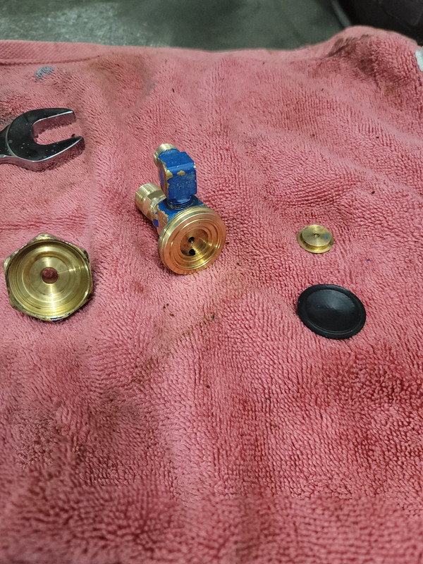
Ok, so the problems continue. I took the hydraulic unloader apart, it's a very simple thing, just a rubber diaphragm, and a brass disc. It seemed loose, so I cleaned it, tightened it up, and I ran a tap through the top fitting threads, because they seemed to be binding up.

So now that it's all back together, the pump runs but only unloaded.

Before, the pump would run, and then start making air shortly after, except it would drain through the unloader, at least until I pinched the line.

I'm at a bit of a loss. How did I suddenly change this thing to only run unloaded....
 

JHForman

Well-known member
Joined
Jul 30, 2019
Messages
111
Location
Floyds Knobs
Ok, so the problems continue. I took the hydraulic unloader apart, it's a very simple thing, just a rubber diaphragm, and a brass disc. It seemed loose, so I cleaned it, tightened it up, and I ran a tap through the top fitting threads, because they seemed to be binding up.

So now that it's all back together, the pump runs but only unloaded.

Before, the pump would run, and then start making air shortly after, except it would drain through the unloader, at least until I pinched the line.

I'm at a bit of a loss. How did I suddenly change this thing to only run unloaded....


just went through something similar on my quincy. I rebuilt my hyd unloader, after installing it my compressor would only make 30 psi then sit there unloaded. after seeing someone mention it looks dropped, I think you need a new hyd unloader. I thought i got mine rebuilt just fine but i messed up somehting in there.
 
OP
I

InjectorService

Well-known member
Joined
Dec 11, 2019
Messages
266
Location
Canada
just went through something similar on my quincy. I rebuilt my hyd unloader, after installing it my compressor would only make 30 psi then sit there unloaded. after seeing someone mention it looks dropped, I think you need a new hyd unloader. I thought i got mine rebuilt just fine but i messed up somehting in there.
It's definitely not been dropped. The black goop you see on the fitting to the unloader is RTV. Those threads were messed up a bit, and the pipe thread fitting wouldn't turn in. (This is how i got it) I ran a tap though it and now it's fine. There's no physical damage on this thing, other than the oil filter being beat up a bit.
 

JHForman

Well-known member
Joined
Jul 30, 2019
Messages
111
Location
Floyds Knobs
It's definitely not been dropped. The black goop you see on the fitting to the unloader is RTV. Those threads were messed up a bit, and the pipe thread fitting wouldn't turn in. (This is how i got it) I ran a tap though it and now it's fine. There's no physical damage on this thing, other than the oil filter being beat up a bit.

good to know it wasnt dropped!! can you post a better picture of the unit so we can see all the plumbing?
 
OP
I

InjectorService

Well-known member
Joined
Dec 11, 2019
Messages
266
Location
Canada
Here you guys go.

I've been doing some thinking, does this pilot unloading system even do me any good with a pressure switch? Can I even set it to run continuously?

20230919-080906.jpg

20230919-080911.jpg
 

MacMcMacmac

Well-known member
Joined
Oct 21, 2014
Messages
1,593
Location
canada
If there is no valve to isolate the pilot, it has to be set higher than the pressure switch or it will run constantly and unload. If it is set higher than the pressure switch then it is useless since it will cut out before the pilot valve actuates. I can't really see how it's plumbed but if it doesn't split the signal line between the hydraulic unloader and the pilot, with an isolation valve for the pilot, it is not installed correctly. The pilot is unnecessary complexity if you aren't going to use it. Save it for the gas powered unit. At least take it out of the equation and see if the hydraulic unloader is working properly.
 

The Tool Tyrant

ALLIANCE MEMBER
Joined
Dec 19, 2011
Messages
2,182
Location
Bonita, Ca. (San Diego)
I see no mention that you indeed even have a pressure switch. As Mac has stated, without a valve to switch between start-stop (pressure switch) and continuous run (pilot valve) your current plumbing is set-up for constant run only.
Start off replacing your hydraulic unloader... https://pacificaircompressors.com/p...loader-assembly-0-200-psi-standard-lubricant/ Note that in the Rotary Comp Tech video, that he has the ball valve to switch between modes AND it also requires a check valve, which is located within the Tee fitting above his pilot valve.

Of course, if you want to have either the option of dual control, OR just want the start-stop control, you'll need to add a pressure switch.

That's a more current ROC as it contains the heavier/ thicker cylinder cooling fins.
 
Last edited:
OP
I

InjectorService

Well-known member
Joined
Dec 11, 2019
Messages
266
Location
Canada
Ok, so I have done a bunch of playing and dissing around, and come to some great findings.

1. The compressor was actually loading the whole time, as it should, it was my fault that I didn't realize this.
2. I have removed all of the unnecesary plumbing components, only the hydraulic unloader is left on the machine.
3. I have dissasembled the hydraulic unloader and there are definately parts missing. There should be a fitting on top of the unloader that contains some more parts, maybe a spring or 2 and some sort of check valve (maybe?). The quincy parts breakdown does not show this at all. And it also seems like this piece would have some sort of straight thread (not pipe thread) which is why the threads looked good, but still cut a bit when I ran the tap through.

Its all a little bit frustrating, as Quincy doesn't show or describe any of this properly, and now I think I have wrecked my hyd. unloader.

My options are now:
1. Buy a complete unloader
2. Buy an unloader repair kit, which would be cheaper, but I don't know where all the pieces go because Quincy doesn't document it. Does anyone here know how this thing would go back together with the repair kit?

 
To avoid these ads, REGISTER NOW!
Top Bottom