How does that work for you? I want to get a new chuck for my press and am a little scared to go with a keyless thinking I might not be happy with it. Does it tighten well enough so that it does not easily slip? What brand and where did you get it? Does the quality seem to be good?Upgraded the 5/8 chuck on my drill press to a keyless type.


You are using an out of date browser. It may not display this or other websites correctly.
You should upgrade or use an alternative browser.
You should upgrade or use an alternative browser.
rattle_snake's random shop projects v0.1
- Thread starter rattle_snake
- Start date
OP
rattle_snake
Well-known member
The keyless chuck is working out OK. I bought a cheap one on Amazon, 29$
Yes it will tighten enough and is convenient. The issue is that it can get stuck shut after using it at very high torque, like a 1" twist drill. Can't open it even with channel locks. The key is to run the drill backwards and it pops loose. That is, if your press can run backwards which usually requires a VFD to do so.
Yes it will tighten enough and is convenient. The issue is that it can get stuck shut after using it at very high torque, like a 1" twist drill. Can't open it even with channel locks. The key is to run the drill backwards and it pops loose. That is, if your press can run backwards which usually requires a VFD to do so.
OP
rattle_snake
Well-known member
Got the engine/front suspension cross member cut out. Fun times.
Lots of grime, so can only plasma cut for so long then have to put out the flames. Lots of smoke....
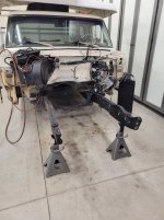
Lots of grime, so can only plasma cut for so long then have to put out the flames. Lots of smoke....
OP
rattle_snake
Well-known member
Yes it was a complete disaster when I bought it, mainly from a leaking steering box. I cleaned what I could, but no way to get it all off. Fixed the leaky box and did many rounds of oven cleaner on the external surfaces. Have to pull the beams to do any better.
The worst was behind the steering box reinforcement, an inch thick.
The worst was behind the steering box reinforcement, an inch thick.
ntsqd
Well-known member
Been there, done that. It’s amazing how much oily, greasy dirt can accumulate in that crossmember
Or even just between two riveted together pieces of steel.
M.Brane
ALLIANCE MEMBER
At least it wasn't rusty.Got the engine/front suspension cross member cut out. Fun times.
Lots of grime, so can only plasma cut for so long then have to put out the flames. Lots of smoke....
OP
rattle_snake
Well-known member
Yup. all the suspension bolts and nuts just came right off after 50 years.

ntsqd
Well-known member
There's method in the madness of allowing the oil leaks?
OP
rattle_snake
Well-known member
Dry climate without salty roads goes a long ways.
Spent hours cleaning up the mess in just the first four feet of frame rails. Baked on like an iron skillet. Scraper, wire wheel, oven cleaner, grinder more oven cleaner.

Spent hours cleaning up the mess in just the first four feet of frame rails. Baked on like an iron skillet. Scraper, wire wheel, oven cleaner, grinder more oven cleaner.
SilverJimmy
Well-known member
Have you tried one of these?
I used to sell the Snap-On version to concrete companies for removing concrete splashed onto surfaces of the delivery trucks. They also work good for stress relieving welds by peening the surface.
I used to sell the Snap-On version to concrete companies for removing concrete splashed onto surfaces of the delivery trucks. They also work good for stress relieving welds by peening the surface.
OP
rattle_snake
Well-known member
No, I have not. Thanks for enabling a tool purchase.
OP
rattle_snake
Well-known member
Did some research on guitar feedback. Suspect the pickup lid is vibrating against the coil itself. The other guitar kit has no lids. Opened up the pickups to see how they are assembled. There is nothing between the pickup coil bars and the cover. Some people use wax to pot the lid on and dampen out the mechanical resonance of the lid.
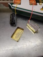
Wax isn't ideal in AZ, instead I used a minimal amount of silicon only around the edge of the bar where it can contact the lid. Solder lids back on and the feedback/squealing issues are gone. Now can turn up to 11 and enjoy. Guitar is cheap, but with some care and minimal money I was able to solve the noise and feedback issues which otherwise ruin the instrument.

I left the pickup wiring as is. Could have removed the wire shield from the pickup baseplate (which is soldered to cover) and ran different wiring. Ideally that would be a shielded pair, which I could make, but don't have anything appropriate at this time.
Pickup baseplate/cover connected to star ground with regular wire.
Pair of signal wires and shield to their respective pot. Shield connected to pot ground/case that is already grounded to star with it's own wire.
Wax isn't ideal in AZ, instead I used a minimal amount of silicon only around the edge of the bar where it can contact the lid. Solder lids back on and the feedback/squealing issues are gone. Now can turn up to 11 and enjoy. Guitar is cheap, but with some care and minimal money I was able to solve the noise and feedback issues which otherwise ruin the instrument.
I left the pickup wiring as is. Could have removed the wire shield from the pickup baseplate (which is soldered to cover) and ran different wiring. Ideally that would be a shielded pair, which I could make, but don't have anything appropriate at this time.
Pickup baseplate/cover connected to star ground with regular wire.
Pair of signal wires and shield to their respective pot. Shield connected to pot ground/case that is already grounded to star with it's own wire.
Last edited:
ntsqd
Well-known member
I used one of the HF tools to remove the remnants of the mortar used for a gosh-awful facade stuck to the fireplace when we bought this house.
A friend of mine used one on a fabricated aluminum intake manifold. With contour grinding and the needle scaler he was able to make the intake look like it was a casting.
When I worked at the power plant the welders there all used a monster sized needle scaler for exactly that, peening a cooling weld.
And oddly enough they're excellent at removing paint and surface rust from stuff like engine blocks and vehicle frames.
A friend of mine used one on a fabricated aluminum intake manifold. With contour grinding and the needle scaler he was able to make the intake look like it was a casting.
When I worked at the power plant the welders there all used a monster sized needle scaler for exactly that, peening a cooling weld.
And oddly enough they're excellent at removing paint and surface rust from stuff like engine blocks and vehicle frames.
M.Brane
ALLIANCE MEMBER
The PO of my Ibanez V potted the bridge pickup with surfboard wax. It's been fine for 40 years that way.Did some research on guitar feedback. Suspect the pickup lid is vibrating against the coil itself. The other guitar kit has no lids. Opened up the pickups to see how they are assembled. There is nothing between the pickup coil bars and the cover. Some people use wax to pot the lid on and dampen out the mechanical resonance of the lid.
Wax isn't ideal in AZ, instead I used a minimal amount of silicon only around the edge of the bar where it can contact the lid. Solder lids back on and the feedback/squealing issues are gone. Now can turn up to 11 and enjoy. Guitar is cheap, but with some care and minimal money I was able to solve the noise and feedback issues which otherwise ruin the instrument.
I left the pickup wiring as is. Could have removed the wire shield from the pickup baseplate (which is soldered to cover) and ran different wiring. Ideally that would be a shielded pair, which I could make, but don't have anything appropriate at this time.
Pickup baseplate/cover connected to star ground with regular wire.
Pair of signal wires and shield to their respective pot. Shield connected to pot ground/case that is already grounded to star with it's own wire.
ntsqd
Well-known member
OP
rattle_snake
Well-known member
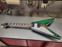
Changed out some of the gold hardware to tone it down a bit. Black pickup covers, and HW. White knobs with gold markings.
OP
rattle_snake
Well-known member
Made some progress on the F100. Used some 1/2 pipe to hold the frame rails in position. The unused/unneeded holes in the frame irritate me. Especially the one I caused from removing things. Have to weld em up and grind em down.

Prepped left side for hole removal. To do a decent job and not get a bunch of contaminates in the weld, have to grind both sides and clean the barrel of the holes with a carbide burr. Since it is a structural item, I try to repair the holes as good as the base metal. Set welder same as a normal weld of given material thickness. Using a lower setting is easier, but lacks the depth and heat needed. Yes you can fill the back side with cold welds, but still not best practice. I go back and fill the back side at same power to get them to full pool. Then knock the humps off enough that the surface can be cleaned and not cut myself.
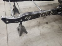
Put down acid etch primer on the bare metal. I spent some time cleaning the front of the cab and touched up the paint where it can't be seen when assembled.
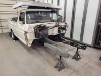
With most the holes filled and slicked out, I am finally at the starting point for the first few feet of frame. Then back to swiss cheese at the cab mount. 18 holes in the next 12 inches.
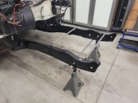
The right side frame rail has additional clearance for the exhaust. The lower flange is bent down, and I cut the top flange to fit the headers. After many hours of deliberating how to reinforce the frame, I decided to box some areas instead of other methods. One area being between the IFS cradle and the rear LCA mounts.
Just welding in a box plate to the downward slope can be done, but will **** to make any kind of radius. Grinding to fit will make a knife edge and welder will liquify it. So I used a big adjustable wrench and bent the lower flange back mostly flat to make an angle joint
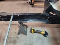
Then trimmed it and the flap in front of it to about 1-1/2 to make maximum clearance for the header. Will still have to modify header to fit properly.

Test fit the IFS to see what the fitment would be like as the fame changes width.
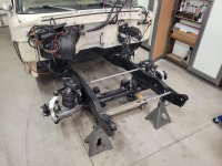
Ready to start cutting. Moving front end forward 2", up 1".

Cut a relief 1" up into the frame. This allows the truck to sit 1" lower, and be able to make flat, full width mounting plates to the cradle on the bench. Drilling holes in the bottom of the frame *****. For the transitions I cut a triangle slice out ot be able to bend the bottom up to the new level and keep the radius.

I figured 1" was about the max before the frame needs to be notched for the LCA rea mount.

IFS in it's almost final location

The mount holes in the IFS are not the same width. The forward set are farther apart. The holes are close to the edge of the frame web. If just bolted on, the hole would go into the radius. This also removed some of the contact area of the cradle mount points. The frame really needs to be widened and not radiused, hence the new plates that can be positioned as needed for better fitment.

Bent the bottom flanges and welded up the seam.

Next step is to make the plates and get them installed. Have to decide if I want to sleeve long bolts, or just bolt to bottom flange only. With frame boxed I'm not sure the sleeves will help. Could weld captive nuts, but would be very difficult to replace if needed.

Prepped left side for hole removal. To do a decent job and not get a bunch of contaminates in the weld, have to grind both sides and clean the barrel of the holes with a carbide burr. Since it is a structural item, I try to repair the holes as good as the base metal. Set welder same as a normal weld of given material thickness. Using a lower setting is easier, but lacks the depth and heat needed. Yes you can fill the back side with cold welds, but still not best practice. I go back and fill the back side at same power to get them to full pool. Then knock the humps off enough that the surface can be cleaned and not cut myself.
Put down acid etch primer on the bare metal. I spent some time cleaning the front of the cab and touched up the paint where it can't be seen when assembled.
With most the holes filled and slicked out, I am finally at the starting point for the first few feet of frame. Then back to swiss cheese at the cab mount. 18 holes in the next 12 inches.
The right side frame rail has additional clearance for the exhaust. The lower flange is bent down, and I cut the top flange to fit the headers. After many hours of deliberating how to reinforce the frame, I decided to box some areas instead of other methods. One area being between the IFS cradle and the rear LCA mounts.
Just welding in a box plate to the downward slope can be done, but will **** to make any kind of radius. Grinding to fit will make a knife edge and welder will liquify it. So I used a big adjustable wrench and bent the lower flange back mostly flat to make an angle joint
Then trimmed it and the flap in front of it to about 1-1/2 to make maximum clearance for the header. Will still have to modify header to fit properly.
Test fit the IFS to see what the fitment would be like as the fame changes width.
Ready to start cutting. Moving front end forward 2", up 1".
Cut a relief 1" up into the frame. This allows the truck to sit 1" lower, and be able to make flat, full width mounting plates to the cradle on the bench. Drilling holes in the bottom of the frame *****. For the transitions I cut a triangle slice out ot be able to bend the bottom up to the new level and keep the radius.
I figured 1" was about the max before the frame needs to be notched for the LCA rea mount.
IFS in it's almost final location
The mount holes in the IFS are not the same width. The forward set are farther apart. The holes are close to the edge of the frame web. If just bolted on, the hole would go into the radius. This also removed some of the contact area of the cradle mount points. The frame really needs to be widened and not radiused, hence the new plates that can be positioned as needed for better fitment.
Bent the bottom flanges and welded up the seam.
Next step is to make the plates and get them installed. Have to decide if I want to sleeve long bolts, or just bolt to bottom flange only. With frame boxed I'm not sure the sleeves will help. Could weld captive nuts, but would be very difficult to replace if needed.
plain2car
Well-known member
HOLY COW!! you have been busy..... well as usual! so I guess I missed it.. what is the IFS make? RideTech?? I am looking to upgrade my '86 C10 front.. thinking QA1 coil overs... thoughts? as opposed to air bags? my main concern is reliablity as the truck is daily driven. as far as the geetar ( ) goes... I think that green kinda clashes with the green on the F250... although I imagine you would still look ok sittin' on the tailgate serenading the wife!! 
) goes... I think that green kinda clashes with the green on the F250... although I imagine you would still look ok sittin' on the tailgate serenading the wife!! Looking good Justin. I’d suggest if you’re going to through bolt it add the sleeves. If you don’t in time that compression point will fatigue a bit. I know it’s pretty stout but I also know you’ll put this truck thru its paces.
OP
rattle_snake
Well-known member
The IFS is a 'junkyard makeover', aka crown Vic with turd polishing. Replaced anything worn or broken. Slicked the castings some and spray paint. Found NIB shockwave air struts on FBMP for cheap.
OP
rattle_snake
Well-known member
Have to bolt it on somehow. If using long bolts through full height of frame then must sleeve. but are long bolts needed?Looking good Justin. I’d suggest if you’re going to through bolt it add the sleeves. If you don’t in time that compression point will fatigue a bit. I know it’s pretty stout but I also know you’ll put this truck thru its paces.
Have a few options:
-long bolts and sleeves, 3/16 thick plates, 3/16 box
-short bolts, 3/16 plates (frame is 0.150)
-short bolts, 1/4 thick plates
-short bolts, 3/16 plates with 3/16 overlay on the bolt holes.
The crown vic frame is fully boxed so Ford used long bolts through the frame for simplicity, cheap. They are also needed to secure the upper bracket that ties in the coil tower. I'm not going to use the upper bracket, as they don't fit the F100 frame. Instead tabs from the frame to the coil buckets. The frame boxing will stop at the forward bolt, so I can access the nuts inside that section of frame.
I found some DOM of odd size. 0.666 ID and 1.25-somehting OD. That makes for .300 wall and is too much/heavy for this purpose.
In general, I'm trying to make the chassis as light as possible. Add material for strength only where needed. Wherever that is
Last edited:


ntsqd
Well-known member
Compared to longer bolts under the same loading, short bolts are more brittle. Re: GM 4WD Square Body steering box bolts, when the frame flexed they'd snap the short ones, but the long ones survived. They just added spacers and used longer bolts all around. Ended the problem.
I'd go with long bolts and sleeves. Set up the sleeves to clamp the bottom flange between it and the cross-member, only weld them at the top flange. Use as big of a bolt as will fit thru the holes in the cross-member, and take it to it's max torque. I'd even consider calling up Genuine Hardware for those bolts and nuts in an AN, NAS or MS spec. You only get four bolts, and you danged sure don't need those working slightly loose.
I'd go with long bolts and sleeves. Set up the sleeves to clamp the bottom flange between it and the cross-member, only weld them at the top flange. Use as big of a bolt as will fit thru the holes in the cross-member, and take it to it's max torque. I'd even consider calling up Genuine Hardware for those bolts and nuts in an AN, NAS or MS spec. You only get four bolts, and you danged sure don't need those working slightly loose.
Last edited:
OP
rattle_snake
Well-known member
Why not weld the bottom of the sleeves to bottom flange?
Going to use 5/8 bolts. The OEM 16 mm studs are too long for how I'm going to do it.
Looking at how deep in the rear bolt is in from the front, I think sleeves and long bolt are the way to go.
Going to use 5/8 bolts. The OEM 16 mm studs are too long for how I'm going to do it.
Looking at how deep in the rear bolt is in from the front, I think sleeves and long bolt are the way to go.
OP
rattle_snake
Well-known member
Made the new frame adapter plates out of 3/16 x 3 flat bar. Was going to use CNC plasma, but design is simple enough to just do manually. The VFD on drill press make quick work of 5/8 or 3/4 holes. Also helps I can sharpen drill bits pretty good now.

Fit perfectly on the subframe.

Cleaned up the horizontal cut on the frame so it sits level to the frame. Bent the lip of the frame flanges to hold it in place and set the roll angle level.

Guessing the outside will sit something like this. Going to get the IFS under the frame again and bolt the plates on before tack welding them in place. How to fully weld without warping them will be a challenge.
Spent some time putting in another brace where the factory RA cross member was. The frame was twisted 5-6* just from the weight of the cab sitting on the leveraged mounts. Used some DOM and a bolt to make a spreader (porta-power would be nice). The frame was off over an inch, got it back in shape and welded in some tube before moving forward with the IFS mount plates. Otherwise the IFS bolted in would prevent spreading the frame there later.

Fit perfectly on the subframe.
Cleaned up the horizontal cut on the frame so it sits level to the frame. Bent the lip of the frame flanges to hold it in place and set the roll angle level.
Guessing the outside will sit something like this. Going to get the IFS under the frame again and bolt the plates on before tack welding them in place. How to fully weld without warping them will be a challenge.
Spent some time putting in another brace where the factory RA cross member was. The frame was twisted 5-6* just from the weight of the cab sitting on the leveraged mounts. Used some DOM and a bolt to make a spreader (porta-power would be nice). The frame was off over an inch, got it back in shape and welded in some tube before moving forward with the IFS mount plates. Otherwise the IFS bolted in would prevent spreading the frame there later.
ntsqd
Well-known member
It's just easier to not do that because then the length of the spacer doesn't need to be so tightly controlled. I prefer to use a 'T' weld bead instead of a flush bead anyway. It also gives me a warm-fuzzy that should the bead crack all the way around there is still a solid capture of the frame.Why not weld the bottom of the sleeves to bottom flange?
Going to use 5/8 bolts. The OEM 16 mm studs are too long for how I'm going to do it.
Looking at how deep in the rear bolt is in from the front, I think sleeves and long bolt are the way to go.
Just to be an enabler I found a company called Temco on the jungle that makes hole punches and dimpling tools that can be driven with a hyd. cylinder. I combined that with an HF pump & puller cylinder and that has me close to having a porta-power.
M.Brane
ALLIANCE MEMBER
I know our OCD tells us otherwise, but most vehicles can tolerate a large amount of misalignment before it actually becomes noticeable.
OP
rattle_snake
Well-known member
OK that make sense.
Not sure I need any more enabling, but the needle scaler is handy.
Not sure I need any more enabling, but the needle scaler is handy.
ntsqd
Well-known member
I don't know, we spent a full week on an Elva Mk VIIs "squaring up the chassis" and re-aligning it after the first track test day showed that while it was technically aligned it was not as fast as it should have been. Making all of the control arms the same length as their opposite, moving holes in the chassis that were slightly off, stuff like that. Plumb-bobs and tape measures, no alignment rack. We gained about 2 seconds per lap on Willow Spring's main track with that work.I know our OCD tells us otherwise, but most vehicles can tolerate a large amount of misalignment before it actually becomes noticeable.
Street car probably won't be as obvious or as affected, but I'd still try to make it as square as reasonably possible.
OP
rattle_snake
Well-known member
Made a quick trip to the steel yard and found a piece of DOM about the right size for sleeves. 1 x 0.75, 8 feet long, just fit in my car. DOM rems are $3/lb.
OP
rattle_snake
Well-known member
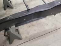
Made some progress on the frame mods. Finished fitting the left side plate and test fit the k member. The more I look at the frame the worse it seems. The truck was hit when parked on the left front. The left frame rail is straight along length and the right side is not. Right side is twisted also, from -2* to +3*. Spent some time trying to resolve and get the right rail vertical and in better alignment. Cut and repositioned some of the braces. It's a 1976 Ford pickup so nothing is perfect. Have to accept that. Got the plates tack welded in. With the K-member holding things the forward two braces are not really needed anymore. The forward end of the right rail still noticeably bent out. Cut some tacks and got it pulled in as good as it is going to get.

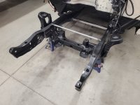
The frame plates landed about where expected from the measurements. I used some block of 1" aluminum to center the structure in the frame
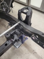
The entire width is needed to use the whole contact pad area. Should made them 1/8 out farther to get the outer edge of forward contact pad.

Fully welded the plates to the frame on both sides. Did in sections skipping around like torquing a head gasket.
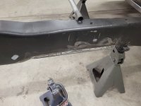
Has some issues with welder after putting a new roll of wire on. Seems to be doing OK now, just needs a better operator.

Cut some 0.750 x 1.000 DOM for bolt sleeves.
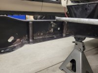
Still a lot of work to go on the front end but on the downhill side now.
The frame plates landed about where expected from the measurements. I used some block of 1" aluminum to center the structure in the frame
The entire width is needed to use the whole contact pad area. Should made them 1/8 out farther to get the outer edge of forward contact pad.
Fully welded the plates to the frame on both sides. Did in sections skipping around like torquing a head gasket.
Has some issues with welder after putting a new roll of wire on. Seems to be doing OK now, just needs a better operator.
Cut some 0.750 x 1.000 DOM for bolt sleeves.
Still a lot of work to go on the front end but on the downhill side now.