To avoid these ads, REGISTER NOW!

Rear Sway Bar Build

astroracer

Well-known member
Joined
Jun 22, 2005
Messages
3,001
Location
Mid_Michigan
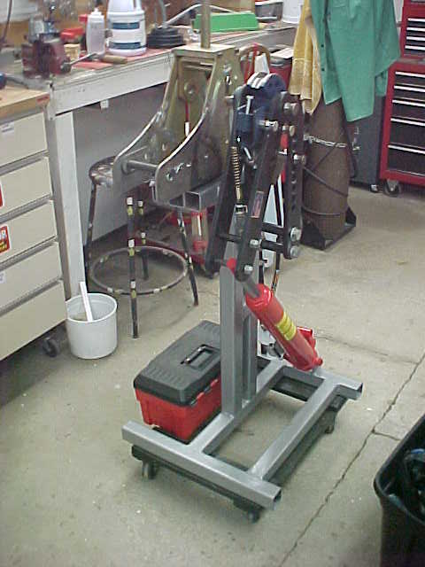
I haven't posted much of the BadAst project here, little bits now and then but I thought some of you would be interested in it. I did post the build of the bender stand here a few years ago and thought you would like to see how it works.
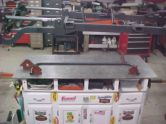
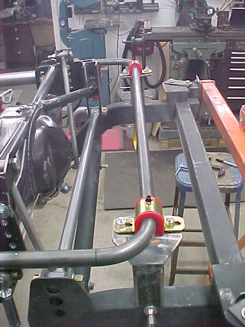
I rolled the tubing bender out so I could get the rear anti-roll bar bent up.
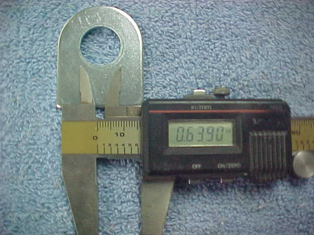
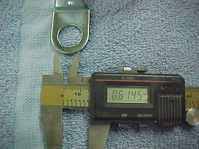
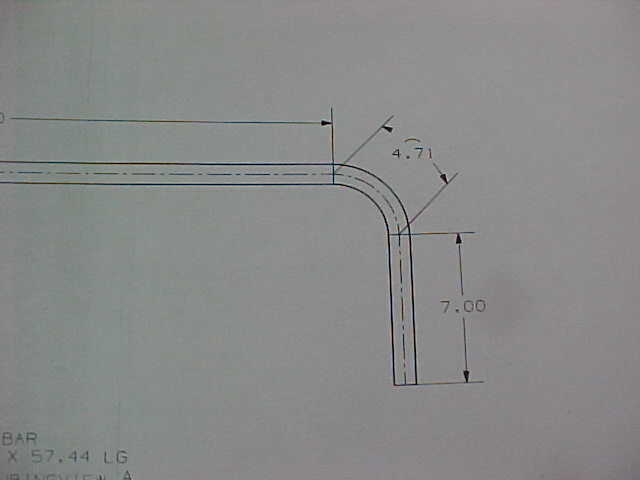
I had made a drawing of the bar in CAD (back in 2013...) with dimensions so laying it out took no guess work. The 4.71 dimension is the arc length of the "centerline" of the bend. This is the length of tubing used to make the 90deg bend between the tangents.
MVC009S-vi.jpg

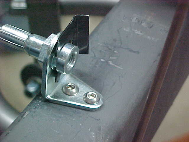
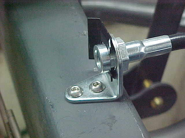
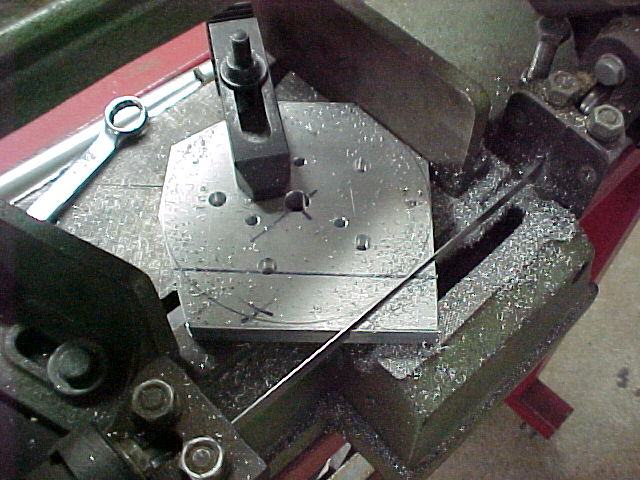
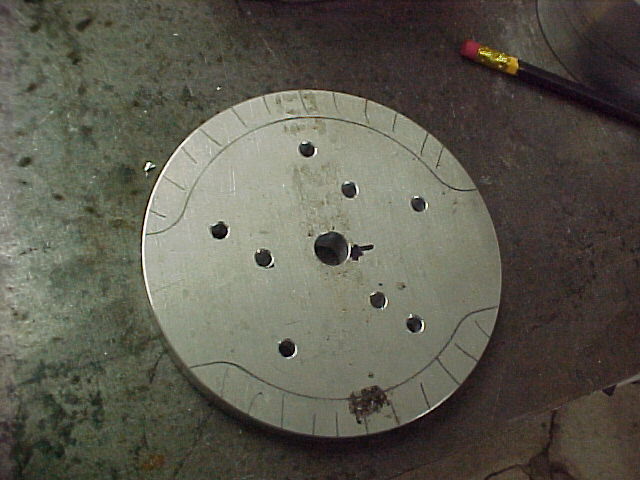
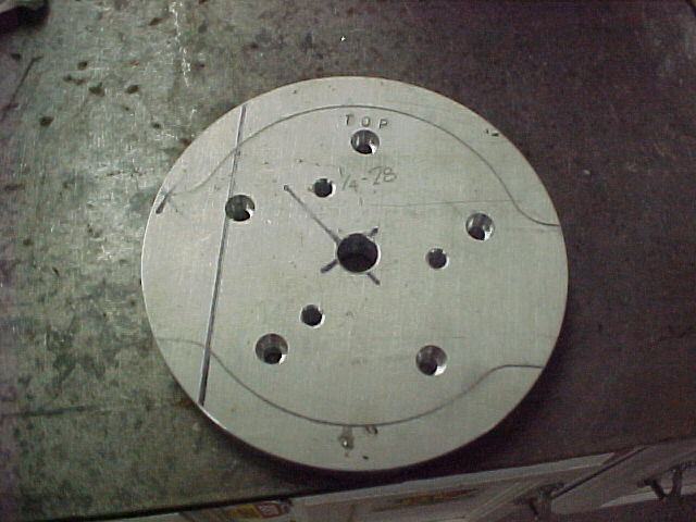
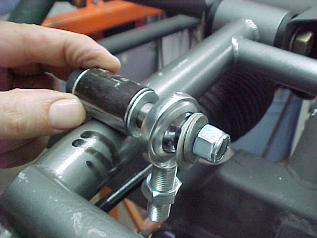
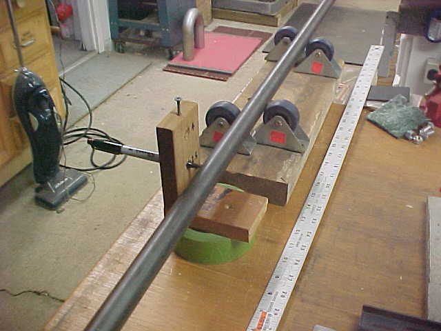
Using the roller jig to mark the tubing. I laid out the tangent lines just like the drawing said. Rolling the tubing in the jig gives me a perfectly straight line, all around the tubing, at each tangent point. This makes setting it up in the bender easy.
MVC010S-vi.jpg


MVC012S-vi.jpg

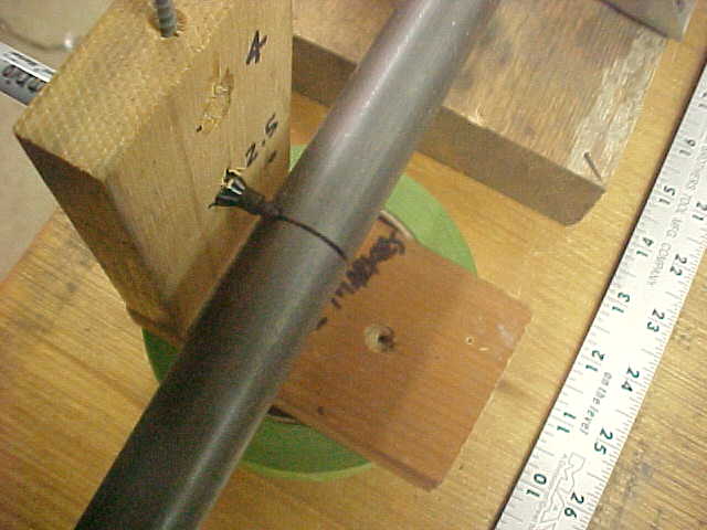
Here you can see the two tangent points laid out for one bend.
MVC007S-vi.jpg


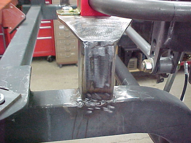
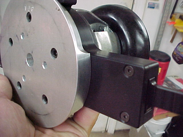
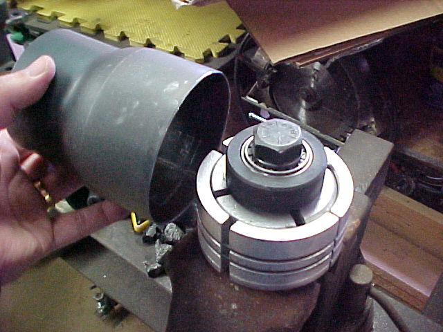
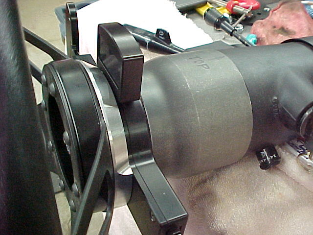
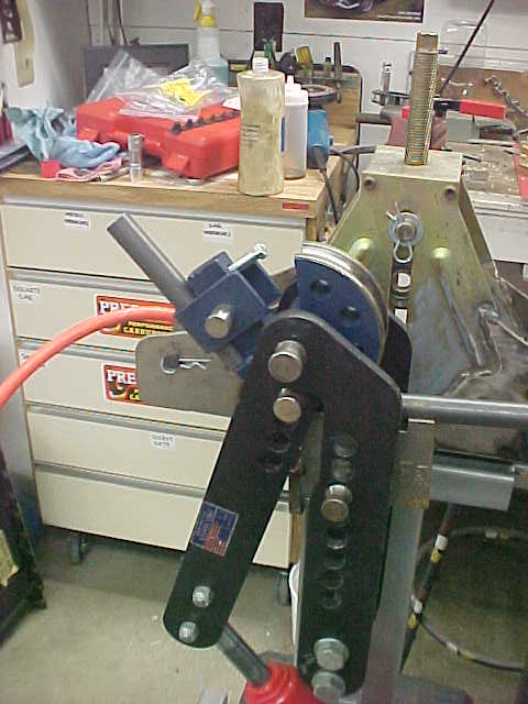
Getting the bender set up. Having it on the cart AND automated, sure does make this less of a chore. The rear bar is 1" O.D. x .095 wall 4130 Chrome Moly. It bends pretty easy anyway but this makes it fun. :)
MVC004S-vi.jpg

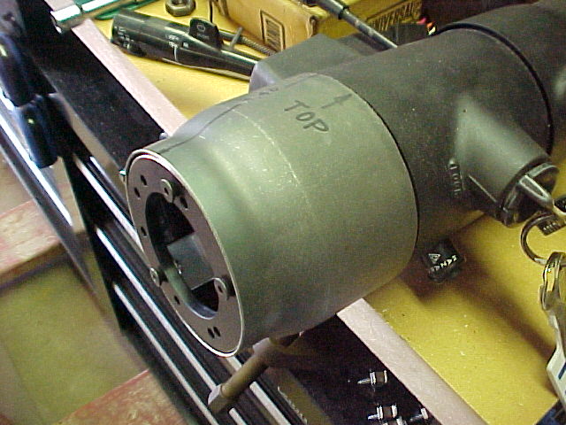
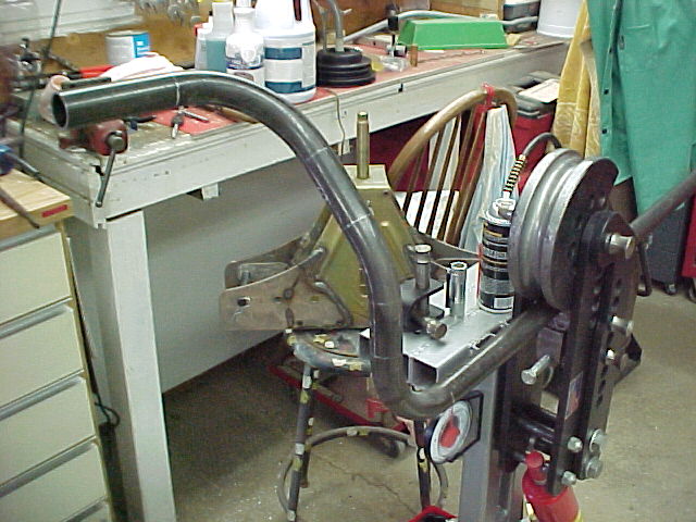
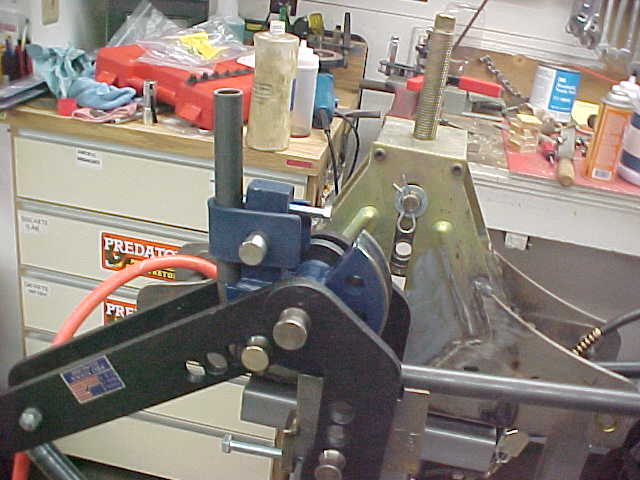
Set up for the 1st bend and about a 1/2 of the way through it.
MVC014S1-vi.jpg


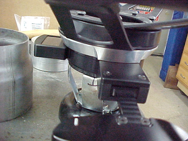
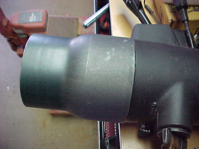
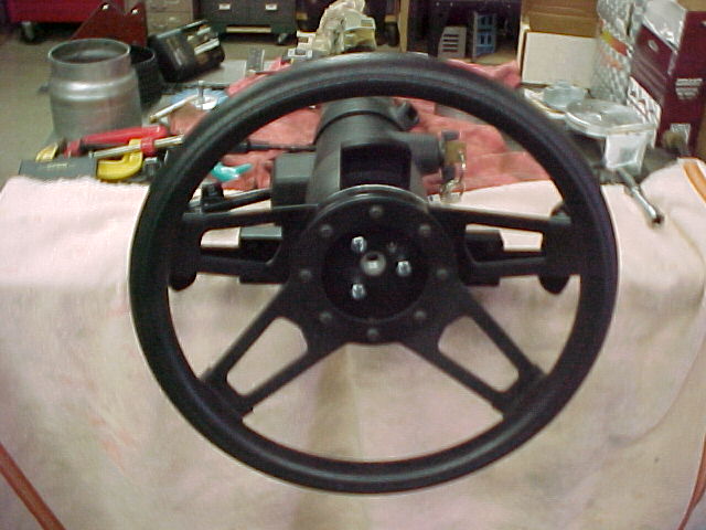
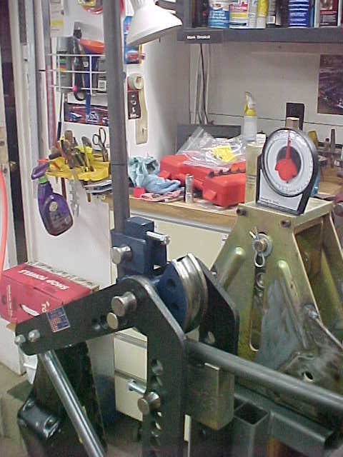
Out to 90 degrees. I am sneaking up on 90 here. To get "90" the tubing needs to be over bent so that, when it springs back, it stays at 90. I over bend it a bit, stop, loosen the jack screw to let the machine relax, measure the bend then bend a bit more if needed. I did this twice for the first bend and once for the second. Knowing what it takes helps with the second bend.
MVC015S-vi.jpg

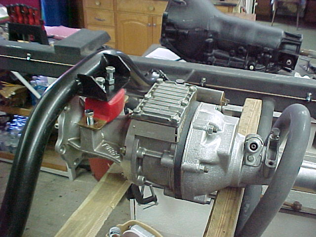
getting the second bend done.
MVC016S1-vi.jpg

Part of doing this correctly is making sure the second bend is on the same plane as the 1st bend. Having one leg point up and the other pointing down is not a good thing.
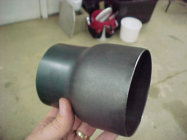
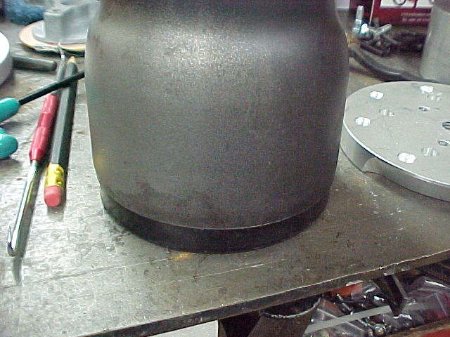
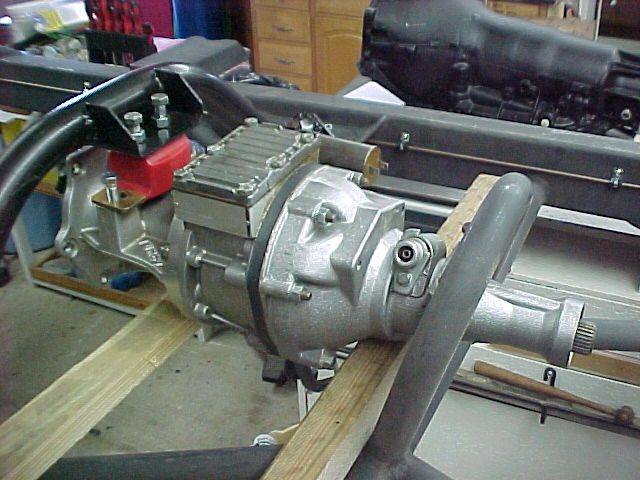
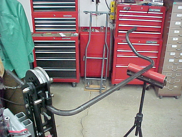
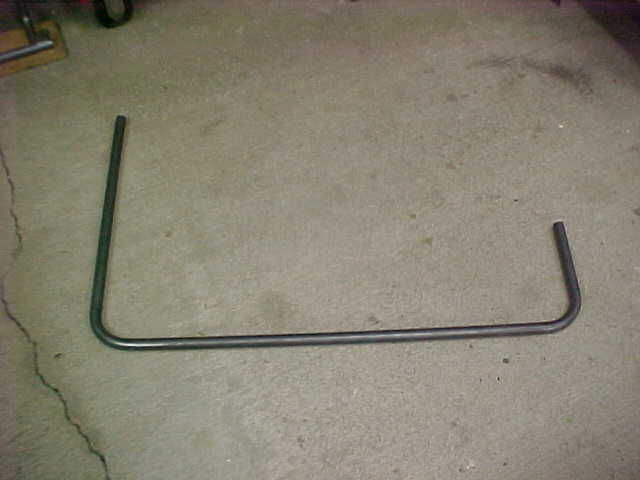
This is the bar after bending. Setting it on the floor tells me if I got it right or not. No rocking in either direction means I got it right.:)
MVC017S-vi.jpg

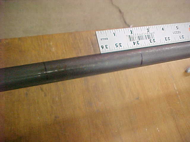
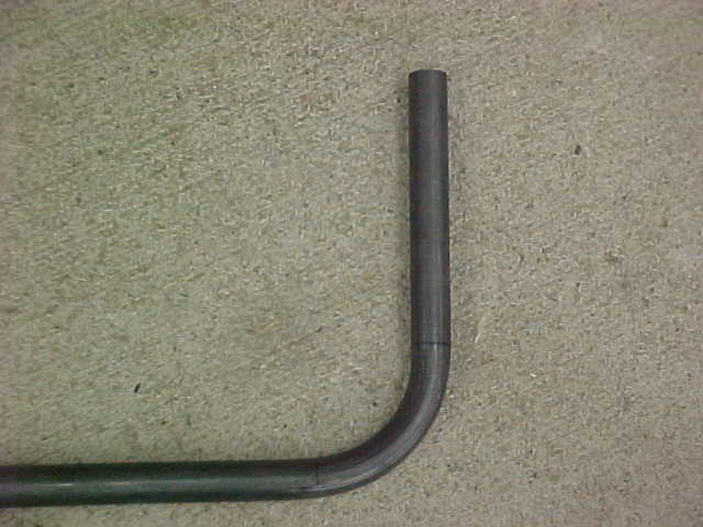
In this pic you can see the tangent points and where they fell in the bend.
MVC018S-vi.jpg

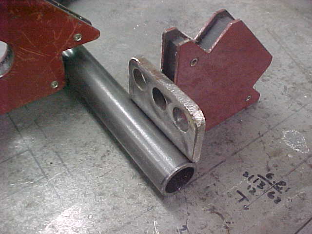
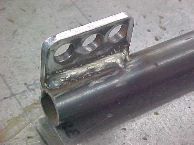
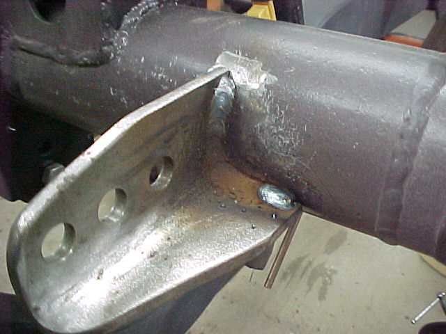
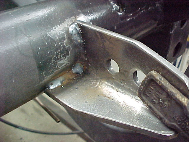
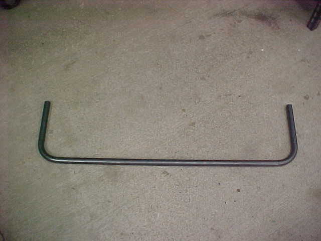
All trimmed up and ready for the endlink tabs to be welded on. I won't do that until I get the rest of the system mocked into place on the chassis so I can tack everything at one time.
MVC020S-vi.jpg

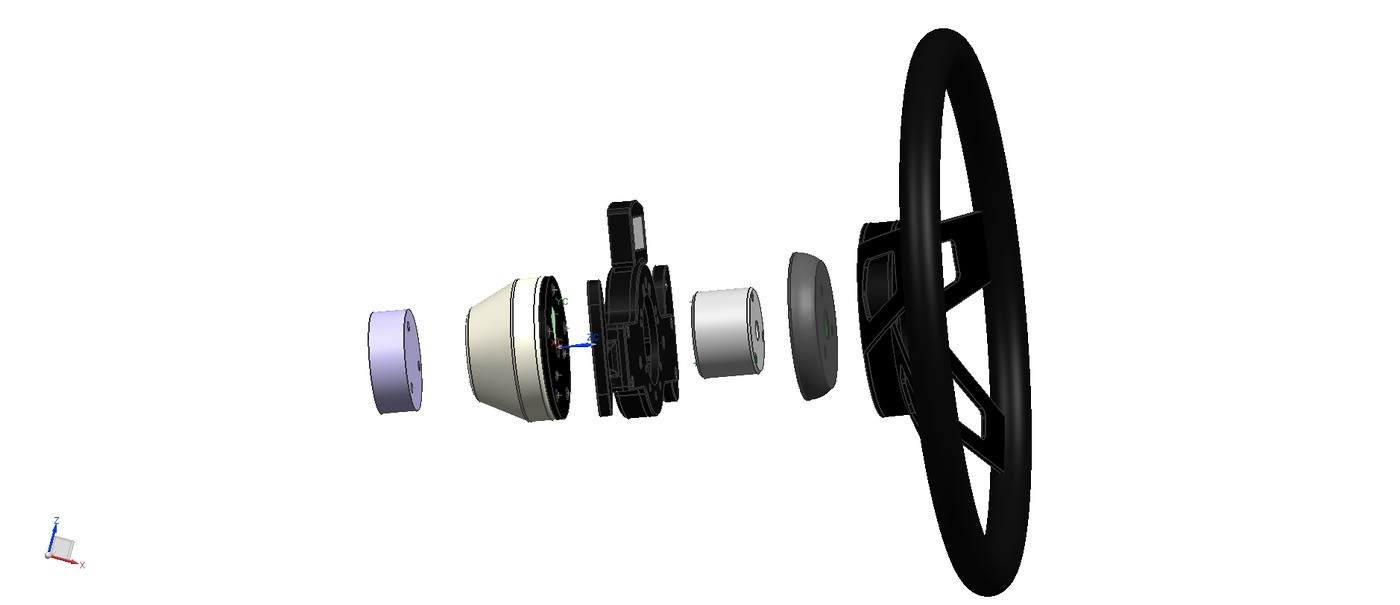
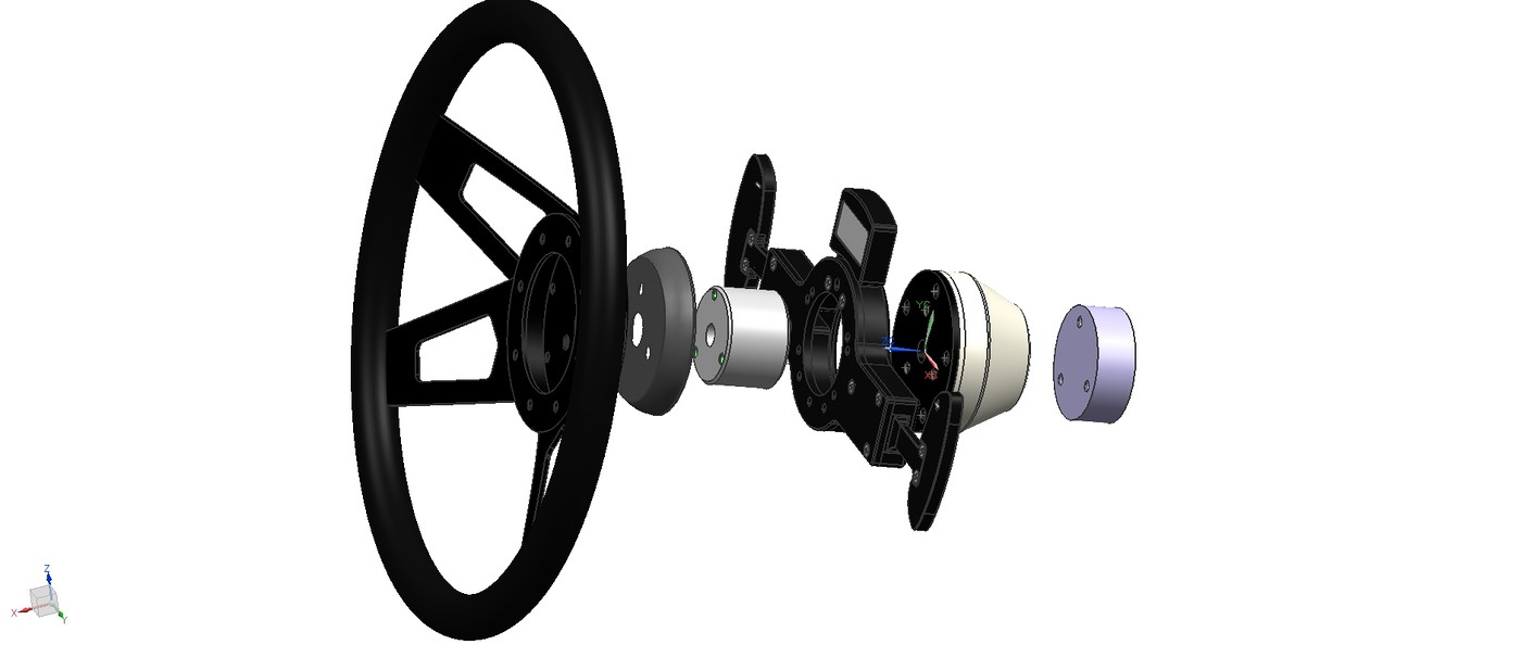
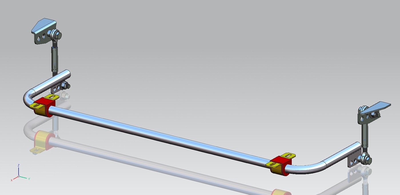
This is how the bar looked in my CAD model.
ASMSWAYBARREAR1-vi.jpg

Thanks for following.
Mark
 
To avoid these ads, REGISTER NOW!

Daveo

Well-known member
Joined
Nov 24, 2012
Messages
146
Very nice!

I need to build a custom one for a project....What metal did you use and are you heat treating it?
 
Last edited:

kabinenroller

Well-known member
Joined
Sep 14, 2013
Messages
898
Location
S.E. Wisconsin USA
Great job on the fabrication so far. Are you planning to have the bar (tube) heat treated? Even if the chrome moly tubing would twist in its original form I would think welding the brackets on the end would change the Rockwell.
I build a bar for my hot rod years ago, I welded mounts to the ends so I could connect the links to the axle pad. After fabricating, welding and test fitting I had it heat treated to make sure it would twist but not bend when the suspension went through it's travel.
Post more pictures as you progress.
 
OP
A

astroracer

Well-known member
Joined
Jun 22, 2005
Messages
3,001
Location
Mid_Michigan
Thanks guys! Hey airrj! How are you?
Lots of questions, I knew there would be. All of your questions are stated pretty much in the 1st post so simply read thru it again. You'll see.
And Red, the tube drawing is dimensioned to the centerline. That's the only way to get a good bend. :)
As far as the heat treat goes, I worked with a suspension engineer on this and he said the Chrome Moly wouldn't need heat treating, it's pretty tuff stuff, and the weld heat is right out at the end so it won't affect the rest of the bar. We'll see how it goes though. if it breaks or takes a set I'll just make a new one and THEN have it heat treated. :)
Mark
 
OP
A

astroracer

Well-known member
Joined
Jun 22, 2005
Messages
3,001
Location
Mid_Michigan
Read the link for easier more repeatable tube fabrication instructions. Though I understand your way works for you.
Red
Sent from my iPad using Tapatalk

I don't understand why you feel my method is any different from the link you posted...It's exactly the same method and is very easy and repeatable. It's just done in the computer using 3D models I created with the correct radius of my bending dies.
Everything is dimensioned to the tube centerline in my drawing. The 4.71 dimension is the "arc length" of the centerline of the bend. That is the straight line length of the bend. Nothing is more easier then laying out those two tangent points you see in my first post and then bending to them... Piece of cake.
Mark
 

bigredmf

Well-known member
Joined
Jan 2, 2012
Messages
414
Location
Between Boston and Detroit
I don't understand why you feel my method is any different from the link you posted...It's exactly the same method and is very easy and repeatable. It's just done in the computer using 3D models I created with the correct radius of my bending dies.
Everything is dimensioned to the tube centerline in my drawing. The 4.71 dimension is the "arc length" of the centerline of the bend. That is the straight line length of the bend. Nothing is more easier then laying out those two tangent points you see in my first post and then bending to them... Piece of cake.
Mark

No disrespect intended but from my 30 year experience of working from that type of drawing it is particularly frustrating.

Say you build a prototype and then ask a manufacturer to make you 100 pieces, the linked method is easier to duplicate and without being condescending the proper way to dimension tubes. I have utmost respect for you using CAD but figured with you taking the time to do it in CAD you may be interested in an alternate way.

The linked method will result in accurate bends regardless of the radius block used. Say you are using a 3.5" radius Vs. the 3.0" someone else has in stock it saves them from having to interpolate your drawing.

Respectfully

Red
 
OP
A

astroracer

Well-known member
Joined
Jun 22, 2005
Messages
3,001
Location
Mid_Michigan
Thanks Red. No harm, no foul. You have to understand though, I am the only one working from these drawings, I have only one radius die for 1" dia. tubing and there is definitely no one going to make another 100 pieces of this bar.
Your concern is noted but it is unnecessary for the work I am doing on the van. It is ALL one off stuff and there is no other application for these parts outside of this build :)
I do thank you for the link! It is one I hadn't seen before and I did print it out for myself and a co-worker for bending brake and fuel lines. VERY handy to know and have in the tool box.
Mark
 

Daveo

Well-known member
Joined
Nov 24, 2012
Messages
146
From what I read, all of the force will be on the middle of the sway bar and not the ends... Maybe scribe a line across it to see if it twists somewhere down the road...
 

airrj

Well-known member
Joined
Apr 4, 2008
Messages
137
Location
Wide Wonderful Wyoming
Mark, Just living the life in Antarctica. Internet here *****, so I don't get on the board very often. Any time I see a post with your name on it, it is always worth taking a look at. Keep up the good work.
 
OP
A

astroracer

Well-known member
Joined
Jun 22, 2005
Messages
3,001
Location
Mid_Michigan
Mark, Just living the life in Antarctica. Internet here *****, so I don't get on the board very often. Any time I see a post with your name on it, it is always worth taking a look at. Keep up the good work.

Thanks bud, I'll try to keep it going. What are you doing down in Antarctica!?!?
 
OP
A

astroracer

Well-known member
Joined
Jun 22, 2005
Messages
3,001
Location
Mid_Michigan
Hold on, this is for an Astro van? Do you have a build thread somewhere?

Yea, it's for an Astro Van. :)
I have a complete build thread on the Pro-Touring forum. 36 pages.
http://www.pro-touring.com/threads/20086-The-BAD-AST-Project-Faze-II
The design work starts in '06 with the actual build getting going in '11. We hit it hard for 2 1/2 years then took a break for 3yrs. I am just now getting back into it. :3gears:
Mark
Dig through the thread and let me know what you think.
 
OP
A

astroracer

Well-known member
Joined
Jun 22, 2005
Messages
3,001
Location
Mid_Michigan
Fire Department at McMurdo, a research base. Fire Inspector/Investigator to be specific.

Does that keep you pretty busy or do you have other duties besides that? Sounds like a neat place to be for a while. How long are you on station?
Mark
 
OP
A

astroracer

Well-known member
Joined
Jun 22, 2005
Messages
3,001
Location
Mid_Michigan
Got a few things done in the last couple of days. Tonight I got the tabs welded onto the stab bar and got that mocked up.
MVC031S-vi.jpg


MVC027S-vi.jpg


MVC032S-vi.jpg


MVC033S-vi.jpg


Mocked up on the stands with bushings.
MVC001S3-vi.jpg


MVC002S4-vi.jpg


Thanks for watching.
Mark
 
OP
A

astroracer

Well-known member
Joined
Jun 22, 2005
Messages
3,001
Location
Mid_Michigan
I got around to ordering the springs for the coil overs this week. Got them thru Speedway, they were on sale and, with free shipping, I saved a bit of cash.
MVC025S-vi.jpg

Mocked up on a shock. I also got the Thrust bearings that go between the spring and lower seat.
MVC026S-vi.jpg


Instead of welding on the brake tabs I decided to go with these bolt on guys. I think this will be a lot cleaner on the frame. As you can see I have them bolted down already.
MVC011S2-vi.jpg

MVC014S-vi.jpg

I did have an issue with these though. As received the hole for the brake line was to small. I had to drill them out with a 5/8ths bit to get the line to go in.
This was one of the straight tabs I had been using.
MVC020S-vi.jpg

This was the hole size in the new tabs...
MVC019S-vi.jpg

.025 makes a big difference here.
Mark
 
To avoid these ads, REGISTER NOW!
OP
A

astroracer

Well-known member
Joined
Jun 22, 2005
Messages
3,001
Location
Mid_Michigan
Back to work on the Astro, sort of... Working with Craig at Bowler we have the PCS Shift Controller and Paddles on their way. PCS has downloadable files available so I downloaded an IGES file of the paddles and added them into my Steering Wheel File.
Getting the paddles to work will require a fabbed adapter to go thru the paddles to pick up the steering wheel bolts. No biggie, I have a lot of 2 1/2" alum bar stock to make it out of.
ASMSTEERINGCOLUMN13-vi.jpg

With the 2" extension, the .81 thick paddle assembly and the 1/2" thick cover I am moving the steering wheel about 4" in the right direction. This should work well with the moderate set back of the driver seat.
Looking down the column.
ASMSTEERINGCOLUMN8-vi.jpg

here is the stack from the passenger side. The little silver part is the adapter I have to make. Everything else I will have.
This remote shifter thing was a bit spendy but it was something I needed to do to get the engine cover cleaned off. Too much stuff going on in too small of an area.
ASMSTEERINGCOLUMN14-vi.jpg

Hopefully the PCS stuff will get here in a timely manner.
Mark
 
OP
A

astroracer

Well-known member
Joined
Jun 22, 2005
Messages
3,001
Location
Mid_Michigan
OP
A

astroracer

Well-known member
Joined
Jun 22, 2005
Messages
3,001
Location
Mid_Michigan
Been a while since I got any reportable work done on the van. Getting sick for a week put a real crimp on my energy level and I am just now getting back to a feeling good point.
Went out today and finished setting up all of the rear stab bar components. Centered the rear housing in the chassis and got all of the links and brackets mocked up. Marked everything for cleaning up the weld areas of paint and broke out the flap disc grinder.
With everything cleaned up I got the welder fired up and welded on the stab bar towers.
MVC011F-vi.jpg


MVC003F-vi.jpg

With thos set I mocked the stab bar back up and got the rear brackets welded on.
MVC005F-vi.jpg


MVC007F-vi.jpg

it all looks good with the links bolted back in.
MVC002F-vi.jpg

MVC014F-vi.jpg


i also did some work on the steering wheel adapter for the PCS shifter set up. Cut a chunk of 1/2" aluminum cut out and marked to start making it.
Got a lot done today, thanks for watching.
Mark
 
OP
A

astroracer

Well-known member
Joined
Jun 22, 2005
Messages
3,001
Location
Mid_Michigan
Got a bit more done last night. Ran the front suspensions thru jounce and rebound and full L/R lock. Laid out the final positions for the steering stops and got those tacked in.
After grinding the paint off I marked the positions with black felt pen.
MVC001F-vi.jpg

Checking the positioning and making sure everything is in the right spot. This is the passenger side as the frame is upside down on the rotisserie.
MVC004F-vi.jpg

This is the driver side front stop tacked on.
MVC010F-vi.jpg

I will pull the spindles out to finish the welding. I had everything wrapped in welding blankets while tacking but I didn't want to put that kind of heat into the blankets.
MVC009F-vi.jpg

I probably should have rounded those corners over before I tacked them on... Oh well the big grinder will get a work out. :)
Mark
 
OP
A

astroracer

Well-known member
Joined
Jun 22, 2005
Messages
3,001
Location
Mid_Michigan
Nice work Mark. I don't recognize the spindles, what are they?

Thanks RJ,
The spindles are aftermarket 2" dropped Astro spindles. The steering arm has been heavily modified for the custom steering geometry dictated by the Corvette rack I designed the suspension around.
Mark
 

airrj

Well-known member
Joined
Apr 4, 2008
Messages
137
Location
Wide Wonderful Wyoming
2" drop Astro spindles, I guess that is why I did not recognize them. I haven't thought much about suspension design in several years, your photos have me dreaming about Ackerman and roll centers.

Keep up the good work and keep the photos coming.
 
OP
A

astroracer

Well-known member
Joined
Jun 22, 2005
Messages
3,001
Location
Mid_Michigan
Thanks!
Here is some more updates. To make a new shroud to cover the steering column extension I ordered a couple of 4 to 3 1/2" reducers from Speedway. I also bit the bullet and ordered a tubing expander kit from Lisle. This will come in handy for exhaust work anyway and it does have a role in this kind of fab work also.

I set up the new, larger adapter plate in the mill and got some work done on that. Making the hole patterns, trimming out the blank and machining it round just like the previous one.
MVC002F-vi.jpg


Holes drilled and c'bored.
MVC003F-vi.jpg

I'll be milling an angle on the back side of the adapter to reduce the diameter to better match the shift unit.
This is the back side I will be milling. The pencil line is the size of the shifter unit.
MVC005F-vi.jpg


Setting up the rotary table in the mill I needed an adapter to locate the plate concentric to the center of the rotary table. I machined this out of a piece of 1" diameter aluminum stock.
MVC016F-vi.jpg

The larger end pilots in the center bore of the table and the small end pilots into the center hole of the plate. I used a long bolt and a couple of spacers to mount the plate to the table.
MVC002F1-vi.jpg


After getting the piece aligned in the mill I tipped the mill head so I could cut the 40 degree angle I needed. Sad to say I could only tip the head about 32 degrees because of the Frankenmills' questionable construction...
MVC006F-vi.jpg


I got both back angles milled. Not as steep as I was planning but I think they will work.
MVC012F-vi.jpg


MVC003F-vi.jpg

I mocked up the adapter plate and I think it will look better then the previous attempt.
MVC006F1-vi.jpg

It should look great after some cleanup and satin black paint.
MVC007F1-vi.jpg
 
OP
A

astroracer

Well-known member
Joined
Jun 22, 2005
Messages
3,001
Location
Mid_Michigan
A week ago Sunday morning I was in the shop at 9:00am. I worked out there for an hour or so and started not feeling well... Anyway, I got sick Sunday morning and was out of commission until Friday afternoon. You name the symptom and I had it. :( Stomach, chills, sweats, aches (even my hair hurt) and the dreaded I.C.B. (Irritable Colon Blow...). Wednesday thru Friday I couldn't keep anything in that went down. Literally, water would run right thru me. I think I lost about 10lbs. I started feeling better Friday morning and have been on the uptake ever since.
I got out in the shop Saturday and got a lot of work done, trying to make up for the rest of the week I lost.
Here are the reducers I got from Speedway. These look real nice, smooth with a clean, even transition.
MVC001F-vi.jpg

I also got the pipe expander kit I ordered off Amazon. This worked very well and was worth the coin. This will get a lot of use in the shop.
MVC013F-vi.jpg

Expanding the 4" end to slip over the cover bell that came in the adapter kit. This took about 5 minutes once I got the kit set up.
MVC013F-vi.jpg

I didn't have to go far, maybe an eighth of an inch.
MVC003F-vi.jpg

Once it was a nice slip fit I slipped it all together on the column. I think this will look much cleaner then that convoluted boot.
MVC016F-vi.jpg

MVC008F-vi.jpg

Thanks for looking!
Mark
 
OP
A

astroracer

Well-known member
Joined
Jun 22, 2005
Messages
3,001
Location
Mid_Michigan
I got out this morning and finished up the cover. Got it trimmed "almost" to length and, with the length established I could expand the 3 1/2" to slip over the upper plate. Mocked up the wheel and paddles.
Cut to length and expanded to fit.
MVC001F-vi.jpg

With the paddles and steering wheel adapter attached.
MVC003F-vi.jpg

MVC010F-vi.jpg


With the wheel bolted up.
MVC008F-vi.jpg


MVC009F-vi.jpg

I think I am going to paint the column, new cover and the adapter plate with a satin black. I have to paint the column because there will be an open wound after I remove the shift lever lump...
MVC006F-vi.jpg

That's all for this week... Thanks for following!
Mark
 
OP
A

astroracer

Well-known member
Joined
Jun 22, 2005
Messages
3,001
Location
Mid_Michigan
well that just looks awesome :D

Thank You Sir, much appreciated.
Just a little info, this is what I was building with stuff I had in the shop. I think I did well replacing the convolute with the smooth cover...
MVC007F-vi.jpg

As it is now, with no paint.
MVC007F-vi.jpg

Thanks for watching.
Mark
 
OP
A

astroracer

Well-known member
Joined
Jun 22, 2005
Messages
3,001
Location
Mid_Michigan
With the column stuff sorted out I am moving on to other things...
I dug out the trans and GV unit tonight. I was curious to see how much of a tear up I would have. I designed and built the K member and trans cross member around a 700R4, not figuring on finding a gear vendor unit for as cheap as I did. I took some measurements off the mock-up 700R4, the TH400 trans and the GV unit.
The 700 was 22.31 from the engine face to the trans mount bolts.
The 400 WITH the GV unit measures 27.31 inches to the trans mount bolts.
Subtracting the 22.31 from the 27.31 ='s 5.00 inches. That is how far I have to move the trans cross member rearward to pick up the trans mounting bolts in the gear vendor unit.
I don't have 5 inches in the cross member tabs welded to the chassis BUT I can flip the cross member 180 degree to move the trans mounting tab to the rear. Doing that gets me 3.50 inches. (the tab WAS 1.75 inches in front of the cross member centerline so, flipping it 180 moves it 1.75 inches BEHIND the centerline. 1.75 plus 1.75 is 3.50. So now all I have to move the cross member is 1.50 inches... Easy. And the GV unit fits in the loop comfortably. No changes ! YA HOO!
MVC006F-vi.jpg


MVC005F-vi.jpg


MVC004F-vi.jpg

Now, granted I had planned to use the loop as a driveshaft loop so I will have to think about that one. I may end up moving just the loop...
Mark
 

Lwel9226

Well-known member
Joined
Jun 7, 2014
Messages
764
Location
So Oregon
Mark..
I agree, getting rid of that convolute is a big improvement...... The whole project is looking good... :beer:

LynnW
FoBW
 
OP
A

astroracer

Well-known member
Joined
Jun 22, 2005
Messages
3,001
Location
Mid_Michigan
Well, I got bit by the measure twice cut with an axe bug Saturday afternoon... Working on the front stab bar, I got it designed and detailed and started doing the bends. The tubing is 1.25" x .125 wall 4130 so it is not cheap... I had 6 bends to do and got the first 4 correct. The 5th bend I got out of position by 2.75 inches. I went to the wrong side of the tangent line by that amount so now I have a piece of useless spaghetti standing in the corner...

Anyway I have another 100 dollar piece of tube standing next to the bender so tonight I will give it another shot. I did take the "opportunity" to redesign the bar a bit and make it simpler. Now it just needs 4 bends so, if I can keep my record going I should be able to do this... :)
Pictures will be forthcoming, good AND bad.

My local steel supplier can't get 4130 or 4140 in any tubing sizes smaller then 3 inches... I ordered this from Online Metals Monday morning and it was delivered Tuesday afternoon, not to bad in my book.
Mark
 
OP
A

astroracer

Well-known member
Joined
Jun 22, 2005
Messages
3,001
Location
Mid_Michigan
Here are some pics of the ruined stab bar...
Everything was looking good as I got these 3 bends completed.
MVC007F-vi.jpg

Even the forth bend came out in the right spot. BUT, if you look at the tube where it is exiting the bending die, you can see a silver line wrapping around the tube a couple of inches out from the bender. That is the tangent line where the bend I am doing in the pic NEEDS to be... Heavy sigh.
MVC010F-vi.jpg

The new design eliminates the two 90's at each end of the bar. I widened the bar about 2 inches and moved it forward a bit.

I have made some progress though. I got the lower stab bar mounts made that weld to the lower control arm.
MVC014F-vi.jpg


MVC016F-vi.jpg

This is a piece of 1" x 1/4 wall DOM that I beveled on one side to sit on the arm and provide a good welding surface.
MVC015F-vi.jpg
 
OP
A

astroracer

Well-known member
Joined
Jun 22, 2005
Messages
3,001
Location
Mid_Michigan
I also go the mounting plates done for the bushings. I made these out of some 1/4" plate trimmed to size and slotted for adjustment. These will weld vertically into the frame. I thought it looked a lot cleaner then big flat plates hanging off the side rails.
MVC003F-vi.jpg


Mounting to the angled down tubes. These will weld on once I get the paint cleaned off. The chassis is upside down on the rotisserie so this is the drivers side.
MVC005F2-vi.jpg


And this is the passenger side.
MVC008F1-vi.jpg

Thanks for watching.
Mark
 
To avoid these ads, REGISTER NOW!
Top Bottom