OP
Grant Gunderson
Well-known member
That sure puts the Electrical Engineer in the EE name on those newer lathes!Just for comparison, my 10EE was built in 1971. Here is what the electronics looks like in this later unit.


That sure puts the Electrical Engineer in the EE name on those newer lathes!Just for comparison, my 10EE was built in 1971. Here is what the electronics looks like in this later unit.


Don't jump to conclusions....
The spindle had a fair amount of oil in it. However the gear box only had a small trickle. I suspect all of the oil on the inside of the machine base came from a bad gasket on the gear box...
That makes me feel a lot better. When so little oil came out based upon the fill amounts from the manufacture I was quite worried it had been run with a low oil level.Don't jump to conclusions.
My back gear box oil level did not show on the sight gauge when I took delivery. And only a few tablespoons came out when I drained it. When I began adding the 3 pints the manual called for, it began running out from behind the lower sheave. So I stopped and re-drained it, thinking there was a bad shaft seal. Pulled the belts and sheave off only to discover there was no shaft seal, only an oil slinger.
So I much more carefully began refilling to discover that it takes only 0.3 pints, not 3 pints (DTE oil heavy medium). The oil level in the sight gauge is lower than the hole through which the shaft protrudes.


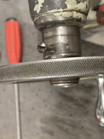
I had thought the button was anodized red, but thats not the case as soon as it contacted the simple green solution in the ultrasonic cleaner all of the red dye came right off of it!
")


Thanks! I thought pretty hard about getting a newer import lathe, but all of the ones around here selling used, all seem to need some work, and where all priced way more than what I picked the 10ee up for. I like to do one or two big projects each summer. My work keeps me busy mid November til May1, but then for the most part I have summers off. Plus what plans we did have for summer this year, are on indefinite hold until more countries open back up for international travel. So the lathe will be my big summer project this year. I was hoping to also build all new cabinetry for my office, but thats on hold until wood prices get back to normal.What a journey Grant. When I decided to step up and get what would be my third lathe, my retired machinist buddy tried talking me into a couple different EE's that were for sale but obviously needed some major love. Knowing I didn't need any new projects and wanting a turn key lathe, I passed. Now after following your story boy oh boy am I glad I didn't go down that road. My hats off to you bud, please keep up this exemplary effort.
Interesting. I just learned something new Doc. Thanks! I always thought of simple green as a pretty mild cleaner as we have been using it to wash our high-end mountian bikes for the last 20+ years. I've even used it in the ultrasonic cleaner regularly with my bike parts with no issues as well for the last 5 years. Then again, now that I think of it, most of my bike parts that I put in the ultrasonic cleaner are titanium, so maybe that has something to do with it.-One of the primary components of Simple Green (and many other cleaners) is lye, or sodium hydroxide. A sodium hydroxide bath is how commercial anodizers strip the plating off of aluminum parts, before re-coloring them.
Simple Green likely wouldn't have hurt the knob if you'd just wiped it down with a cloth or something, but immersed for a half an hour or more in a warm bath stripped it off.
Buff it up and have it reanodized.
Doc.
Do you have any suggestions for a better solution for aluminum parts?
It’s interesting you mentioned Dawn. It had crossed my mind to use it as it seems to cut grease better than a lot of degreasers. In fact I ditched the orange hand soap in favor of it years ago as it just works better. I’ll give it a try in the ultrasonic. You have many issues with it creating too many suds in the ultrasconic?-Dawn dish soap works pretty well. Really, unless you have a specific kind of gunk you're trying to remove, you really just need a soap to break the surface tension and help the dirt float away.
Personally, for non-aluminum parts, I'll use the same Simple Green or Purple Power or whatever "shop cleaner" they have on sale at the local auto parts store. That stuff works great in an ultrasonic.
For aluminum- and I do a lot of small aluminum parts- as well as pot metals like carburetor parts, I've rarely run across something where Dawn didn't work. My timer only goes up to 30 minutes, and usually if the first cycle hasn't done much, fresh water, a little more heat and more Dawn will usually do the trick.
I'll also admit I haven't done a lot of exhaustive research, and tend to use what I have on hand.
Doc.


Doc, that works great. Another option I guess would be enamel with a polyurethane clear coat top.Almost all the machines I've painted I used an alkyd enamel, often over spray self-etching primer. The alkyd cures slowly enough, especially in cooler weather, that it "self levels" nicely. I use a 4" detail roller from Homey-Dee, and get a pretty decent finish.
Before:
And after:
It's proven quite resistant to typical dings and scratches in use, as well as most chemicals it'll see, like way oils, cutting oils, Tap Magic, WD-40, etc.
I will admit a nicely sanded and polished automotive urethane looks great, and I've seen tome top-notch jobs done on big Pacemakers and DSGs, but that sort of thing also takes a great deal of extra work, and requires more care in use. The alkyd enamel touches up easily.
Doc.
...it will brush or roll on quite well...


Paul Nice job on the strip and paint! I've been meaning to up date this thread for a while, but ended up super busy with starting a new company in stealth mode, and now I am on Heli bike trip for work... so hope to get back to the lath next week. I have actually been doing a bunch of paint testing, and finally decided on what I am going to do with the lathe. I ended up using the Sherwin Williams Alkyd for the DC control panel as its a perfect match to the factory color that was on the inside of my lathe. All of the internal paint on my lathe is in really good condition, so I am going to leave it.Grant, just found this thread and I’m quite intrigued. I’m actually doing a full rebuild (everything short of regrinding and scraping the ways) of my own 10EE though just a couple years younger (‘47) and a square dial model.
Mine is currently torn down to individual components with the only remaining assembled parts being the ways bolted to the base casting, was afraid I’d twist the ways trying to bolt them back to the base if I loosened that connection.
I‘m no expert in paint myself but researched all kinds of machine rebuild posts across the internet forums. I used Scherwin Williams Kem-Kromik primer (extremely happy with this product) brushed on the interior and HVLP sprayed on the exterior, top coat painted the interior with rustoleum rattle can (only cuz I didn’t want to lay inside with a brush any longer after learning what that was like after priming, also figured the HVLP with its air hose would be a bear to maneuver around given all the weird angles and surfaces inside), on the exterior I applied two top coats of SW Pro Industrial Urethane Alkyd Enamel (oil based not the water based variant to make it easier to spray). The top coat went on great and I’m really happy with how it turned out. I don’t have the lathe in service yet to know how it holds up to the wear and tear but it cured rock hard after about 3 weeks, sounds like a long time but if you rebuild as slow as I do the next assembly is barely


The epoxy primer, 2K primer and the 2K poly top coat all are two part mixes with a pot life. Even taking my time working slowly, the pot times are more than adequate, but I wouldn't want to let them sit before cleaning the gun.I like the sound of your paint system Grant. I will definitely be trying it out on my next restoration.
Are any of your paints two part mixes with a pot life?
Lastly, not sure on forum etiquette first time poster. So sorry if I’m high jacking your thread. I can message privately if that’s what should be done here. Though in my mind a question asked in public allows everyone else to learn along the way too.