To avoid these ads, REGISTER NOW!

Remoting drip legs in compressed air system

LHC

Well-known member
Joined
May 10, 2010
Messages
48
Hi Folks -
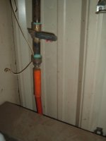
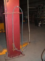
I'm working on my air distribution layout and there are several places that are not easily accessible for the usual ball valve, and drip leg arrangement. I have seen somewhere (possibly years ago on this site but I can't locate it at the moment) where people have actually remoted the drip condensate by using poly tubing and then routing the poly line back up the air pipe (zip tied) and then located the drain at an alternate location.

The theory seems sound - slugs of water that collected in the drip leg and the P trap created with the poly tubing, travel along when the ball valve is cracked at the remote location. If some slugs of water don't make it all the way, and get hung up perhaps in a dip in the tubing part way - who cares - they eventually make it after the next cycle or two anyway.

I really like this approach and began searching around for info and an education in push to connect pneumatic fittings and poly tubing.

Then I hit a bit of a snag and thought I would ask the experts on here (!) about it.

I was reading the specs for NITRA tubing and fittings on the Automation Direct website and found these phrases.

Poly tubing specs and fittings spec state – "Do not use fittings with media other than air", but in other places there are statements such as “use caution in water as product may be damaged by surge pressure”.

This is not a potable water application, and I can’t see surges being an issue as when the valve is opened and water is drained, theoretically, once the valve is closed again, there will be nothing but air in the line, or at the very least, slugs of water separated by air, and giving somewhat of a “cushion” to sudden pressure changes in the tubing and fitings. However, given that it will be used to drain condensate it will be exposed to slugs of water that will be resident in the fittings/tubing.

So, sorry for the long winded dissertation, but are there any people on here that have used this approach and can tell me whether I am on a dark path or "all good" ?

Thanks !
 
To avoid these ads, REGISTER NOW!

lonejacklarry

Well-known member
Joined
Jul 16, 2017
Messages
45
Location
Lone Jack, MO (Pop. 1024)
I've never had the amount of condensate that you appear to have. Maybe it's the climate or amount of usage? I use a dehumidifier and that helps cut down on the ambient moisture in the garage.

At the end of my "work" day, I drain the compressor onto the floor and drain the ball valve
equipped down legs as well. It is never enough to warrant a different system.
 
OP
L

LHC

Well-known member
Joined
May 10, 2010
Messages
48
It's not so much the amount of condensate, it's the inability to physically get to the drip leg to drain it. Stems from the same old problem we all have - workshop is too small for the gear we want to hang onto !.... In any case, I need to remote the drip legs output to another location so its easier to drain.
 

dkmc

Well-known member
Joined
Jan 20, 2008
Messages
949
Location
NYS--Upstate in the corn fields
As Bob Vila would say "that sounds like an elegant solution".
Even better, tie in the tank drain with the remotes, and incorporate
a $25 EBAY electric auto drain valve.

As with my response, I'd ignore any concerns about water in the plastic tubing.
 
OP
L

LHC

Well-known member
Joined
May 10, 2010
Messages
48
As Bob Vila would say "that sounds like an elegant solution".
Even better, tie in the tank drain with the remotes, and incorporate
a $25 EBAY electric auto drain valve.

As with my response, I'd ignore any concerns about water in the plastic tubing.

I had planned to do that the same time as I do the remotes. I'm tired of kneeling and grunting when I drain the tank.....

I need to figure out if I can manifold the remote lines together or not - in one place there's a poor mans chiller - i.e. radiator made of vertical sections of pipe on the wall. At the bottom of the "U"s I have drip legs and if I manifold them together I'm sort of short circuiting the function of the radiator in a way. Granted, the drain remote lines will be .25" ID and the radiator is 3/4 so most of the flow is going to go through the radiator sections. If I remote the drip legs on the radiator, they only go about 6-8 feet away to the "master collection point".

Have to be careful and not let this project spin out of control...it's happened before !
 

larry_g

Well-known member
Joined
Apr 28, 2007
Messages
16,877
Location
oregon
Hi Folks - .

This is not a potable water application, and I can’t see surges being an issue as when the valve is opened and water is drained, theoretically, once the valve is closed again, there will be nothing but air in the line, or at the very least, slugs of water separated by air, and giving somewhat of a “cushion” to sudden pressure changes in the tubing and fitings.

Water slugs are a big concern. I've had to repair irrigation heads, big farm stuff, that have been blown apart by someone opening the water flow to fast. As the water rushes down the pipe pushing the air out ahead of it it comes to the valve or nozzle and the water is like a bullet hitting the end of the line. Your good if you flow things slowly. Open the valve wide open and you could have trouble.

lg
no neat sig line
 
OP
L

LHC

Well-known member
Joined
May 10, 2010
Messages
48
Good point Larry - thanks for the input. I generally crack the ball valves slowly so will keep on doing it ! It seems these push to connect fittings also come in all metal versions so if I blow one apart I can up my game with those I guess ... this might explain why the expensive Parker ones are spec'd for fluids and the other cheap ones are not !
 

HotRodHudson

Well-known member
Joined
Nov 18, 2013
Messages
373
Even in the low humidity area I live in I get a fair amount of water off my compressor. What helped me the most was when I built an “after cooler” and put it in between the motor & the tank of the compressor. I don’t know how this will hold up for years to come but it is crazy at dropping the air temperature before it hits the tank.

I have had temps around 350 degrees off the motor & once it goes through the “after cooler” temps are no more than 10 degrees hotter than room temp. I also put a harbor freight water separator after the after cooler & before the tank. The nice thing about this one is that it automatically drains when the pressure in the line drops, probably 5psi or less. The only down side is it’s 40 micron filter which I wish it was a 20 or smaller 10 micron filter. I put a bucket below the drain for now to catch the water it spits out.

Here’s a picture:

IMG_0038.jpgView attachment 1View attachment 1

I used a braided steel line off the motor that’s rated to 450 degrees & the copper is connected by compression fittings.


Sent from my iPhone using The Garage Journal mobile app
 
To avoid these ads, REGISTER NOW!

sberry

Banned
Joined
Jun 18, 2005
Messages
35,747
Location
Brethren, Michigan
I found all but 1 piece in the scrap, had to make 1 flare. Hooks to a hose going thru the wall. I crack a valve once in a while.
I have 3 vessels. All T on to the exhaust line.
 

Attachments

  • air comp drain.jpg
    air comp drain.jpg
    116.2 KB · Views: 41

southalabama

Well-known member
Joined
Jan 10, 2011
Messages
5,535
Location
Brewton AL
Not the same application but I've got a building air conditioning unit drains to a housing with an automatic float switch. From their it goes into a clear tubing up and eventually out the building. The a/c unit is in the middle of the building and was the only way I could get the condensate out. I'm in south alabama. The a/c generates a lot of water.
 
OP
L

LHC

Well-known member
Joined
May 10, 2010
Messages
48
I guess I don't understand this part ???? The only place I have drip legs is where there is an air connection ? Why would you even want one where you cant get to it ????

New equipment - no room - wall space gone - in front of a drip leg that is at a low point that needs to be tended to.
 

sberry

Banned
Joined
Jun 18, 2005
Messages
35,747
Location
Brethren, Michigan
The lowest point is in the tank or vessel. I made some changes to my manifold, re routed lines a bit and don't even have drip "legs on most of mine now. The filter is it and don't get any that far anyway.
Pic 1 is the revision, same equipment. Moved it for a new pipe and a better location from when it was tossed together when I moved in the building. I put local valves on, right on the hard line and any hose or equipment follows. This one is to an old hose reel, used mainly for tires on the apron, it had been on for 20 years and I finally put a more convenient service valve and shut it off until its needed most of the time.
Same for pic 3 and 4. That reg provides service to 4 outlets. 2 fixed whips for the hoist, a couple general reels and a reel with additional reg for paint guns. Last 2 are paint, again service valve shuts it in locally when not needed.
Some of the hydrants are live 24/7, a couple I shut off as their use is incidental.
 

Attachments

  • air 4.jpg
    air 4.jpg
    71.1 KB · Views: 18
  • air 2.jpg
    air 2.jpg
    81.7 KB · Views: 20
  • air reg HD.JPG
    air reg HD.JPG
    35.2 KB · Views: 20
  • air reggie.jpg
    air reggie.jpg
    75.2 KB · Views: 21
  • paint air 2.jpg
    paint air 2.jpg
    93.8 KB · Views: 16
  • paint air dis.jpg
    paint air dis.jpg
    43.2 KB · Views: 16
Last edited:
OP
L

LHC

Well-known member
Joined
May 10, 2010
Messages
48
These things are never really "done" as I am learning - but they do get optimized and better over time as ones workflow tends to dictate the "right" layout. Thanks for the pics and info - gives me more to think about (not that that's always good though - paralysis through analysis etc.....)
 

sberry

Banned
Joined
Jun 18, 2005
Messages
35,747
Location
Brethren, Michigan
Yes, the layout looks different after the fact and one finds out the optimum locations and duty cycle. Sometimes its easier to do something twice rather than figure it all out before. I have 7 drops. I could actually do it with 4 almost as easy. The 3 extra I have are fixed whips and no reels but they are super slick with no real moving parts, don't take extra space or additional equipment. One hangs on a boom to my vise and surrounding area, one each post on thre hoist. I am not sure if I would need the swivel, its been a while since I did it but it was to keep the hose from hugging the corner of the post as it was pulled around.
 

Attachments

  • Hoist air drop.jpg
    Hoist air drop.jpg
    68 KB · Views: 14
  • hoist air 1.jpg
    hoist air 1.jpg
    67.3 KB · Views: 13
  • Hoist hose *******.JPG
    Hoist hose *******.JPG
    46.2 KB · Views: 12
Last edited:

kbs2244

Well-known member
Joined
Nov 11, 2006
Messages
14,065
First, have all horizonal line with some slant to a vertical for drainage,
(This is a belt/suspenders need. Air current will move most moisture downstream)
Second, I have always placed the drip leg at the bottom of the vertical leg, with the outlet on a tee off the vertical.
This makes any moisture make a 90-degree bend before getting to the outlet and allows the drain valve to be as assessable as the outlet.
The drain tube after the drain valve can be anything.
It is not under pressure.
 
To avoid these ads, REGISTER NOW!
Top Bottom