To avoid these ads, REGISTER NOW!

Requesting input on generator connection wiring (with pics)

olytdi

Well-known member
Joined
Dec 3, 2011
Messages
2,202
Location
Olympia, Washington
Hello, I’m hoping that the home generator wiring gurus can weigh-in.

What I inherited (please reference attached photos):

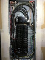
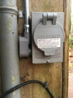
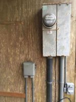
Street power comes to a meter box mounted on an outbuilding that houses the well infrastructure. From the meter, power goes into the attached main disconnect box (pic 1). In this main disconnect box, power is passed through the 200A main breaker (pic 2) then goes underground 80 ft to the house panel (pic 3).

In the main disconnect box, between the 200A main breaker and the cables going out to the house, is a bus bar with a 40A breaker coming from the generator inlet (pic 2). The generator connection is a flanged inlet box fitted with a 50A three prong twist-lock male that has a ground tab on the outer rim (pic 4 and 5).

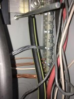
Also coming off of this bus bar are some other breakers that are assigned to the well pump and the well house heater, both of which reside at that outbuilding (pic 2). These breakers have a shared neutral/ground bus bar (pic 6). You can see the braided ground cable that goes to earth ground coming out of the bottom of the box (pic 7).

So, disconnecting the 200A main breaker separates street power and then closing the 40A breaker allows the generator to power that bus bar including the service cables that go on to the house panel 80 ft away as well as the breakers for the well pump and heater residing at that outbuilding.

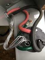
The 50A three prong male twist-lock flanged inlet (pic 8) has lugs for four wires: two for the hot legs (red/black) to the 40A generator inlet breaker, one for the neutral (note that this is a bare twisted aluminum wire) that goes to the neutral/ground bus bar (pic 6), and a fourth lug for the ground (green). The ground is wired to a contact on the inside of the flange) and then to the steel box it’s all housed in (pic 8).

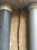
This is the setup I inherited and I don’t know what sort of generator was being used but there is a ground rod about 5 feet away that is driven into the ground (pic 9) and I suspect (but do not know) that the previous owner’s generator had to be earth grounded to it to be safely connected to the layout I’ve outlined above.

My Setup:

My generator is a Honda EU6500is inverter type and the 240V power outlet is a standard female 4 prong 30A 240V twist-lock (L-14-30). I want to power the well pump and the service cables that go on to the house panel but am uncertain about the ground-neutral relationship at the main box (pic 6) and at the house panel (pic 3). The 50A 3 prong inlet wiring also is puzzling to me. From what I can discern, my Honda generator has a floating neutral and does not employ earth grounding so I’m a little uncertain how to proceed with the wiring.

Can I simply discard the 50A 3 prong inlet and substitute it with a standard 30A 4 prong inlet that corresponds to my generator outlet (two hot, one neutral, and a ground) whereby the ground on the new inlet twist-lock is attached to the steel box housing, and the neutral is attached to the neutral bus bar just like the current setup?

If yes, shouldn’t that neutral wire from the generator inlet to the neutral bus bar be an insulated wire instead of a bare twisted aluminum wire?

Is it a problem that all the grounds and neutrals at the main disconnect box (generator inlet, well and heater – pic 6)) are bonded while those at the 200A house panel 80 ft away (pic 3) also are bonded?

I’d like to get my Honda setup to safely power the house from this outbuilding with as little alteration as possible. I’m trying to avoid having to hire an electrician who would undoubtedly be compelled to completely re-do the entire setup probably beyond that which is necessary and at great expense. But I will do so if this setup is so far off in left field that it’s somehow unsalvageable. I successfully wired my last house for use with this generator and it all worked flawlessly but that was to a single main panel with no inherited oddities.

Any and all input is genuinely appreciated!

Thanks up front and Merry Christmas!

Additional photos in next post!
 

Attachments

  • pic 1.jpg
    pic 1.jpg
    87.8 KB · Views: 108
  • pic 2.jpg
    pic 2.jpg
    101.6 KB · Views: 342
  • pic 3.jpg
    pic 3.jpg
    92.7 KB · Views: 122
  • pic 4.jpg
    pic 4.jpg
    91 KB · Views: 103
  • pic 5.jpg
    pic 5.jpg
    54.8 KB · Views: 118
  • pic 6).jpg
    pic 6).jpg
    84.5 KB · Views: 106
  • pic 7).jpg
    pic 7).jpg
    70.2 KB · Views: 86
To avoid these ads, REGISTER NOW!

mike93lx

ALLIANCE MEMBER
Joined
Dec 9, 2013
Messages
37,816
Location
Richmond, VA
is there anything forcing you to shutoff street power when turning on the generator breaker? If not, it's dangerous and illegal.
 

Norcal

Well-known member
Joined
Mar 16, 2008
Messages
13,767
The wiring is all messed up, no interlock between the main & generator feed, grounding & neutrals in the subpanels not seperated, URD cable used inside a structure. Are those panels Challenger, or Bryant/Westinghouse BR? They both used crappy Zinsco mains.
 

Bert_

Well-known member
Joined
Dec 24, 2016
Messages
9,766
Location
NW Iowa
The wiring is all messed up, no interlock between the main & generator feed, grounding & neutrals in the subpanels not seperated, URD cable used inside a structure. Are those panels Challenger, or Bryant/Westinghouse BR? They both used crappy Zinsco mains.

A lot of assumptions here.

We need to see the panel cover to know if there is an interlock. And we would like to see it OP. IF it has an interlock then it's fine. I would replace that bare neutral.

The house may be (and probably is) old enough that a 3 wire feeder to a separate building is perfectly legal. And who's to say that urd isn't also rated RHW or something, lot's of it is.
 
OP
O

olytdi

Well-known member
Joined
Dec 3, 2011
Messages
2,202
Location
Olympia, Washington
Thanks for the replies. I do appreciate them.

With regard to the interlock, no, currently there isn't one. I understand the issues with that and intend to eventually remedy it. But that's not related to my questions though I do appreciate the concerns.

Yes, the house panel is a Challenger circa 1993. The main disconnect at the meter is Square D, I think. I didn't build this, it is what's there.

I understand that it's a sub-optimal setup and once I understand what's appropriate with regard to the generator inlet wiring and how the ground/neutral bonding should, or should not, occur (and where), I will re-design it to be safe (including interlock). I don't want to get hung up on the low hanging fruit of the interlock issue. I'm fully aware.

Let's assume that there is an interlock and that the panels are suitably legal. It's the wiring of generator inlet I'm trying to understand in this context as well as the grounding/bonding at that first panel and in relation to the house panel.

Thanks again!
 

Bert_

Well-known member
Joined
Dec 24, 2016
Messages
9,766
Location
NW Iowa
This is the service panel it is bonded and should be. Neutral and ground can go on the same buss bar.

The house panel is a 3 wire feed, in new construction this would not be allowed but yours was legal when installed so barring any major changes it is still legal. Since it is a 3 wire feed it must be bonded, a 4 wire feed would have neutral and ground separated.
 
OP
O

olytdi

Well-known member
Joined
Dec 3, 2011
Messages
2,202
Location
Olympia, Washington
Okay, thanks, Bert -- that's VERY helpful! So no worries with regard to the bonding at two locations.

So given that, could one would simply wire the generator input with an insulated neutral to the bus bar and then connect the ground to the input housing? I'm asking in the context of this particular generator which is a floating neutral inverter type.

Thank you again!
 

wyliesdiesels

Well-known member
Joined
Aug 14, 2012
Messages
20,066
Location
Modesto, CA
The generator has a 4-wire outlet so need to have a 4-wire inlet. Both neutral and ground would go to the same bonded neutral bus.
 
Last edited:
OP
O

olytdi

Well-known member
Joined
Dec 3, 2011
Messages
2,202
Location
Olympia, Washington
Thanks for the reply, Wylie. Not sure what you meant with "so need to have wire inlet." Could you elaborate?

Wouldn't ground from the inlet be going to the bonded neutral bus by virtue of having been attached to the housing which is steel?

Thanks again.
 

theoldwizard1

Well-known member
Joined
Feb 22, 2011
Messages
43,237
Location
SE MI
I am assuming this is the back side of the inlet.

attachment.php


I don't know which is ground and which is neutral but my gut says this is not right !
 

pattenp

Well-known member
Joined
Jun 4, 2008
Messages
10,175
Location
Virginia - USA
Sorry for not reading all the post but bottom line as I see the inlet it needs to be a four wire/prong inlet. The neutral needs to be isolated all the way back to the service panel and the equipment ground needs to run from the inlet back to the service panel. The neutral and ground should only be bonded in the main service panel. In other words the inlet needs to match generator outlet using a four wire cable back to service panel with at least an interlock on the back fed breaker.
 
Last edited:
OP
O

olytdi

Well-known member
Joined
Dec 3, 2011
Messages
2,202
Location
Olympia, Washington
Wizard,

Yes, that's the back of the (strange) 3 prong 50A twist lock inlet I inherited.

The braided bare wire is the neutral and goes to the bus bar in that main disconnect panel where neutrals and grounds are joined.

That green wire on the back of the inlet is a ground that goes to the housing.
 
To avoid these ads, REGISTER NOW!

tyme2par4

Well-known member
Joined
May 16, 2016
Messages
571
Location
NH
I took a quick look on google, and it looks like that inlet should be wired with 4 wires. The tab at the end of the screw driver is the ground.

To switch to a 30A inlet, you'll have to run a new insulated wire for the neutral. Use the existing bare wire as the ground.

Both of these wires will be landed on the ground bar in the panel.
 
OP
O

olytdi

Well-known member
Joined
Dec 3, 2011
Messages
2,202
Location
Olympia, Washington
Sorry for not reading all the post but bottom line as I see the inlet it needs to be a four wire/prong inlet. The neutral needs to be isolated all the way back to the service panel and the equipment ground needs to run from the inlet back to the service panel. The neutral and ground should only be bonded in the main service panel. In other words the inlet needs to match generator outlet using a four wire cable back to service panel with at least an interlock on the back fed breaker.

Thanks Patten. So this inlet is at the main service panel. The main service panel is the 200A disconnect, a couple of breakers for the well, and then service cable continues on to the full house panel 80 ft away. The ground and neutrals are conjoined at both the service panel and at the house panel.

Given that, can you weigh-in on what you wrote?

Yes! I'm aware of the need for an interlock! Thanks for keeping everyone safe!
 

Norcal

Well-known member
Joined
Mar 16, 2008
Messages
13,767
Bert brought up the possibility that the panel was installed when a 3-wire feed was allowed & based on what the OP has said he is probably correct, the odds are more to a 3-wire feeder being allowed when it was done.
 
OP
O

olytdi

Well-known member
Joined
Dec 3, 2011
Messages
2,202
Location
Olympia, Washington
Thanks, Norcal -- now that I re-read Bert's post above, I see that he did address the question of the bonded-at-both-locations issue. So, yeah, I would have thought that there would have needed to be another service cable going to the house panel for N/Gnd to be separated. And since there isn't, it's bonded at both locations. I'm sure it was code when built in 1993. They're pretty strict around these parts!
 
OP
O

olytdi

Well-known member
Joined
Dec 3, 2011
Messages
2,202
Location
Olympia, Washington
I took a quick look on google, and it looks like that inlet should be wired with 4 wires. The tab at the end of the screw driver is the ground.

To switch to a 30A inlet, you'll have to run a new insulated wire for the neutral. Use the existing bare wire as the ground.

Both of these wires will be landed on the ground bar in the panel.

Perfect! Thanks Tyme! Just what I needed to know!

Does the inlet housing need to be grounded with a wire or is the fact that it's all steel and connected back to the main box make its grounding adequate?

Thanks again!
 

wyliesdiesels

Well-known member
Joined
Aug 14, 2012
Messages
20,066
Location
Modesto, CA
Thanks for the reply, Wylie. Not sure what you meant with "so need to have wire inlet." Could you elaborate?

Wouldn't ground from the inlet be going to the bonded neutral bus by virtue of having been attached to the housing which is steel?

Thanks again.

that was a typo. it shouldve said "4-wire". I fixed it.

Also, generators do not need ground rods....

And neutral should only be bonded in one spot.

your inlet is 4-wire, however, the bare wire for the neutral should NOT be bare. I would definitely fix that as it is a shock hazard.
 
OP
O

olytdi

Well-known member
Joined
Dec 3, 2011
Messages
2,202
Location
Olympia, Washington
that was a typo. it shouldve said "4-wire". I fixed it.

Also, generators do not need ground rods....

And neutral should only be bonded in one spot.

your inlet is 4-wire, however, the bare wire for the neutral should NOT be bare. I would definitely fix that as it is a shock hazard.

Ahhh, okay, got it! Ha. Should've known to put a "4" in there.

Yeah, that neutral bonded only in one spot thing is a conundrum. It's definitely bonded at the main panel and again at the house panel.

Is there anything to do about that short of putting in an entirely new electrical system?

Is there a hazard to the bonded-in-two-locations thing?

Thanks Wylie.
 

wyliesdiesels

Well-known member
Joined
Aug 14, 2012
Messages
20,066
Location
Modesto, CA
Ahhh, okay, got it! Ha. Should've known to put a "4" in there.

Yeah, that neutral bonded only in one spot thing is a conundrum. It's definitely bonded at the main panel and again at the house panel.

Is there anything to do about that short of putting in an entirely new electrical system?

Is there a hazard to the bonded-in-two-locations thing?

Thanks Wylie.

prior to 2008 code cycle, it was permissible to run 3-wire feed to detached structure as long as there were no other parallel metallic pathways.

This however created a shock potential if the neutral ever developed a bad connection because of the bonded neutral in the panel at the detached structure. Hence why they are no longer allowed.
 
OP
O

olytdi

Well-known member
Joined
Dec 3, 2011
Messages
2,202
Location
Olympia, Washington
prior to 2008 code cycle, it was permissible to run 3-wire feed to detached structure as long as there were no other parallel metallic pathways.

This however created a shock potential if the neutral ever developed a bad connection because of the bonded neutral in the panel at the detached structure. Hence why they are no longer allowed.


Okay. Got it. There has to be tens of thousands of examples of this situation out there, no?

I think I'll find an electrician who can at least analyze what I have going on here and make a recommendation in terms of near-term and long-term.

Thank you
 

tyme2par4

Well-known member
Joined
May 16, 2016
Messages
571
Location
NH
Perfect! Thanks Tyme! Just what I needed to know!

Does the inlet housing need to be grounded with a wire or is the fact that it's all steel and connected back to the main box make its grounding adequate?

Thanks again!

You may be able to use the conduit as the ground, but I believe you need a ground bushing on the conduit. I don't think the standard conduit fittings and lock nuts are certified to bond painted boxes.
 
OP
O

olytdi

Well-known member
Joined
Dec 3, 2011
Messages
2,202
Location
Olympia, Washington
You may be able to use the conduit as the ground, but I believe you need a ground bushing on the conduit. I don't think the standard conduit fittings and lock nuts are certified to bond painted boxes.

Okay, that makes sense. I can even just run a ground to the bus bar as it's only a few feet away. I asked because the box (housing) for the inlet has a ground lug on it.
 
OP
O

olytdi

Well-known member
Joined
Dec 3, 2011
Messages
2,202
Location
Olympia, Washington
This is the response I got from another forum dedicated to generators. It captures a lot of the pieces posted previously here and is concise.

1. Add an interlock, as you have mentioned; can't emphasize it enough, though!

2. I suppose you can continue to use that non-standard RV power inlet, but I would change it to a standard L14-30 household generator inlet which will match up with your GenSet and isolate the neutral/ground lines until they bond at the bar.

3. As you said, it looks like your neutral and ground may be bonded at both panels? (It's hard to tell from the picture of the house panel.) That would be a serious question for your local electrician, since usually the bonding is only done at the service entrance, and then they are isolated (floated) at any sub-panels (your whole house in this instance). This can vary locally, though.

4. Your generator should not require a ground rod when serving the inlet shown; it is only necessary when serving its individual outlets when separate from the structure. The generator frame will be grounded through the inlet ground line and the neutral will go to the service neutral (bonded there).

5. I'm kind of puzzled by your panels; seeing many white wires connected to the hot legs (breakers). Those are normally neutrals. Also a question for your electrician...
 

Bert_

Well-known member
Joined
Dec 24, 2016
Messages
9,766
Location
NW Iowa
This is the response I got from another forum dedicated to generators. It captures a lot of the pieces posted previously here and is concise.

1. Add an interlock, as you have mentioned; can't emphasize it enough, though!

2. I suppose you can continue to use that non-standard RV power inlet, but I would change it to a standard L14-30 household generator inlet which will match up with your GenSet and isolate the neutral/ground lines until they bond at the bar.

3. As you said, it looks like your neutral and ground may be bonded at both panels? (It's hard to tell from the picture of the house panel.) That would be a serious question for your local electrician, since usually the bonding is only done at the service entrance, and then they are isolated (floated) at any sub-panels (your whole house in this instance). This can vary locally, though.

4. Your generator should not require a ground rod when serving the inlet shown; it is only necessary when serving its individual outlets when separate from the structure. The generator frame will be grounded through the inlet ground line and the neutral will go to the service neutral (bonded there).

5. I'm kind of puzzled by your panels; seeing many white wires connected to the hot legs (breakers). Those are normally neutrals. Also a question for your electrician...

1-4 have been covered already.

5. Those are 2 pole breakers and obviously a 240V circuit. The absolutely correct thing to do would be color the white wire with a strip of tape or a marker. It was very common to NOT re identify the white wires years ago. Doesn't make it right but it's a pretty minor issue. It's not something that I would worry about even a little.
 
To avoid these ads, REGISTER NOW!
Top Bottom