olytdi
Well-known member
Hello, I’m hoping that the home generator wiring gurus can weigh-in.
What I inherited (please reference attached photos):
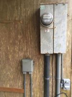
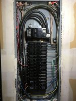
Street power comes to a meter box mounted on an outbuilding that houses the well infrastructure. From the meter, power goes into the attached main disconnect box (pic 1). In this main disconnect box, power is passed through the 200A main breaker (pic 2) then goes underground 80 ft to the house panel (pic 3).
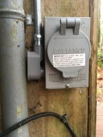
In the main disconnect box, between the 200A main breaker and the cables going out to the house, is a bus bar with a 40A breaker coming from the generator inlet (pic 2). The generator connection is a flanged inlet box fitted with a 50A three prong twist-lock male that has a ground tab on the outer rim (pic 4 and 5).
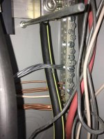
Also coming off of this bus bar are some other breakers that are assigned to the well pump and the well house heater, both of which reside at that outbuilding (pic 2). These breakers have a shared neutral/ground bus bar (pic 6). You can see the braided ground cable that goes to earth ground coming out of the bottom of the box (pic 7).
So, disconnecting the 200A main breaker separates street power and then closing the 40A breaker allows the generator to power that bus bar including the service cables that go on to the house panel 80 ft away as well as the breakers for the well pump and heater residing at that outbuilding.
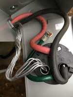
The 50A three prong male twist-lock flanged inlet (pic 8) has lugs for four wires: two for the hot legs (red/black) to the 40A generator inlet breaker, one for the neutral (note that this is a bare twisted aluminum wire) that goes to the neutral/ground bus bar (pic 6), and a fourth lug for the ground (green). The ground is wired to a contact on the inside of the flange) and then to the steel box it’s all housed in (pic 8).
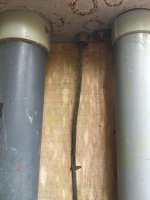
This is the setup I inherited and I don’t know what sort of generator was being used but there is a ground rod about 5 feet away that is driven into the ground (pic 9) and I suspect (but do not know) that the previous owner’s generator had to be earth grounded to it to be safely connected to the layout I’ve outlined above.
My Setup:
My generator is a Honda EU6500is inverter type and the 240V power outlet is a standard female 4 prong 30A 240V twist-lock (L-14-30). I want to power the well pump and the service cables that go on to the house panel but am uncertain about the ground-neutral relationship at the main box (pic 6) and at the house panel (pic 3). The 50A 3 prong inlet wiring also is puzzling to me. From what I can discern, my Honda generator has a floating neutral and does not employ earth grounding so I’m a little uncertain how to proceed with the wiring.
Can I simply discard the 50A 3 prong inlet and substitute it with a standard 30A 4 prong inlet that corresponds to my generator outlet (two hot, one neutral, and a ground) whereby the ground on the new inlet twist-lock is attached to the steel box housing, and the neutral is attached to the neutral bus bar just like the current setup?
If yes, shouldn’t that neutral wire from the generator inlet to the neutral bus bar be an insulated wire instead of a bare twisted aluminum wire?
Is it a problem that all the grounds and neutrals at the main disconnect box (generator inlet, well and heater – pic 6)) are bonded while those at the 200A house panel 80 ft away (pic 3) also are bonded?
I’d like to get my Honda setup to safely power the house from this outbuilding with as little alteration as possible. I’m trying to avoid having to hire an electrician who would undoubtedly be compelled to completely re-do the entire setup probably beyond that which is necessary and at great expense. But I will do so if this setup is so far off in left field that it’s somehow unsalvageable. I successfully wired my last house for use with this generator and it all worked flawlessly but that was to a single main panel with no inherited oddities.
Any and all input is genuinely appreciated!
Thanks up front and Merry Christmas!
Additional photos in next post!
What I inherited (please reference attached photos):
Street power comes to a meter box mounted on an outbuilding that houses the well infrastructure. From the meter, power goes into the attached main disconnect box (pic 1). In this main disconnect box, power is passed through the 200A main breaker (pic 2) then goes underground 80 ft to the house panel (pic 3).
In the main disconnect box, between the 200A main breaker and the cables going out to the house, is a bus bar with a 40A breaker coming from the generator inlet (pic 2). The generator connection is a flanged inlet box fitted with a 50A three prong twist-lock male that has a ground tab on the outer rim (pic 4 and 5).
Also coming off of this bus bar are some other breakers that are assigned to the well pump and the well house heater, both of which reside at that outbuilding (pic 2). These breakers have a shared neutral/ground bus bar (pic 6). You can see the braided ground cable that goes to earth ground coming out of the bottom of the box (pic 7).
So, disconnecting the 200A main breaker separates street power and then closing the 40A breaker allows the generator to power that bus bar including the service cables that go on to the house panel 80 ft away as well as the breakers for the well pump and heater residing at that outbuilding.
The 50A three prong male twist-lock flanged inlet (pic 8) has lugs for four wires: two for the hot legs (red/black) to the 40A generator inlet breaker, one for the neutral (note that this is a bare twisted aluminum wire) that goes to the neutral/ground bus bar (pic 6), and a fourth lug for the ground (green). The ground is wired to a contact on the inside of the flange) and then to the steel box it’s all housed in (pic 8).
This is the setup I inherited and I don’t know what sort of generator was being used but there is a ground rod about 5 feet away that is driven into the ground (pic 9) and I suspect (but do not know) that the previous owner’s generator had to be earth grounded to it to be safely connected to the layout I’ve outlined above.
My Setup:
My generator is a Honda EU6500is inverter type and the 240V power outlet is a standard female 4 prong 30A 240V twist-lock (L-14-30). I want to power the well pump and the service cables that go on to the house panel but am uncertain about the ground-neutral relationship at the main box (pic 6) and at the house panel (pic 3). The 50A 3 prong inlet wiring also is puzzling to me. From what I can discern, my Honda generator has a floating neutral and does not employ earth grounding so I’m a little uncertain how to proceed with the wiring.
Can I simply discard the 50A 3 prong inlet and substitute it with a standard 30A 4 prong inlet that corresponds to my generator outlet (two hot, one neutral, and a ground) whereby the ground on the new inlet twist-lock is attached to the steel box housing, and the neutral is attached to the neutral bus bar just like the current setup?
If yes, shouldn’t that neutral wire from the generator inlet to the neutral bus bar be an insulated wire instead of a bare twisted aluminum wire?
Is it a problem that all the grounds and neutrals at the main disconnect box (generator inlet, well and heater – pic 6)) are bonded while those at the 200A house panel 80 ft away (pic 3) also are bonded?
I’d like to get my Honda setup to safely power the house from this outbuilding with as little alteration as possible. I’m trying to avoid having to hire an electrician who would undoubtedly be compelled to completely re-do the entire setup probably beyond that which is necessary and at great expense. But I will do so if this setup is so far off in left field that it’s somehow unsalvageable. I successfully wired my last house for use with this generator and it all worked flawlessly but that was to a single main panel with no inherited oddities.
Any and all input is genuinely appreciated!
Thanks up front and Merry Christmas!
Additional photos in next post!