
You are using an out of date browser. It may not display this or other websites correctly.
You should upgrade or use an alternative browser.
You should upgrade or use an alternative browser.
Right way to make a Y with stranded wire?
- Thread starter R-mm
- Start date
BonzoHansen
Well-known member
mshell56118
Well-known member
I use these alot https://www.amazon.com/dp/B000JJPA66/?tag=atomicindus08-20 they are awesome and make connections easy in tight space since they are tool free connector
I use these alot https://www.amazon.com/dp/B000JJPA66/?tag=atomicindus08-20 they are awesome and make connections easy in tight space since they are tool free connector
I bought a bunch in various sizes quite some time ago They looked great. In reality, they are too bulky, not watertight, and I've not been able to convince myself of their value.
Bobioz1
Well-known member
Problem with a **** connector is its a compromise for an asym splice, for instance itll never fit one 12ga in, two 12ga out.
Sent from my iPhone using Tapatalk
Strip more insulation off the single wire and then double it over.
nelstomlinson
Well-known member
Solder is not good for power connections because it can melt. Consider wire nuts or Polaris lugs.
Solder is not good for power connections because it can melt. Consider wire nuts or Polaris lugs.
Solder melts at ~ 375 deg f. If your wiring is approaching this temp, you need lower current or bigger wire.
Shiftless
Well-known member
solder melts at ~ 375 deg f. If your wiring is approaching this temp, you need lower current or bigger wire.
seriously!
At what temp does the plastic insulation melt?
The 12 ga I used in conduit to rewire my garage is rated at 90 C max which is 194 F.
IMHO, solder is the gold standard for joining 2 or more wires together.
Last edited:
ez-duzit
Well-known member
These make horrible, high resistance connections.
Much better approach is to either add a terminal strip or use a reducing **** splice connector.
seriously!
At what temp does the plastic insulation melt?
The 12 ga I used in conduit to rewire my garage is rated at 90 C max which is 194 F.
IMHO, solder is the gold standard for joining 2 or more wires together.
If it’s anything like plastic extrusion, about 375 degrees
Strip more insulation off the single wire and then double it over.
^thjs is a good suggestion.
I would ask why you're trying to y-split 12 gauge. And why the load side wires would be the same size wire as the supply wire?
Typically 12 gauge isn't used unless it's for a reasonably high current load (~30A). If that's true, and if the 2 wires that feed the loads need to be 12 gauge then the wire feeding power into the splice would need to be 2x that size, like 8-10 gauge wire so it could support the 2x current demand on one single wire. So you'd want to do one of these things:
1. Use a distribution block instead that can accept a larger wire in and smaller wire out. If you're dealing with high current loads, it might be good to make that a fused distribution block.
2. Use a heavier gauge wire feeding into the spice with the appropriate size **** connector for that wire. This would then be large enough to support 2 or more smaller gauge wires on the other side of the connector.
Assuming you are using the correct gauge of wiring, or a heavier wire than you need, then I've found soldering to be the best method.
The 'T' type taps **** - they are just a bad connection waiting to happen. I've had to replace a lot of them over the years. You are better off just wrapping the wires together and taping them than using those.
But if I understand your situation correctly, I would measure out a single wire all the way from the source to one load.
Then go back to where I need the splice and strip the insulation off about a 1 inch section (give or take depending on wire gauge). Slide a piece of heat shrink tubing down the wire so its behind the stripped section.
Then measure out another piece of wire from the stripped area to the second load and add a little extra. Strip off about 2, 2 1/2 inches or so off the end of this wire and wrap it around the section you stripped off the first wire.
Solder that, then slide the heat shrink tube up over it and shrink it down.
Takes a bit more thought than just chopping them all off, wrapping them together and soldering, but not a lot more, and it looks way better.
I've also doubled the wire over and crimped into a large connection like mentioned above and don't recall having any issues, and I've seen a few on vehicles done by other people and they were doing their job.
I don't like using connectors at all if I can avoid it reasonably, but that's not always realistically possible.
Last edited:
I've used Posi-locks and Posi-taps.
https://www.amazon.com/dp/B00389GGN0/?tag=atomicindus08-20
Haven't had a failure yet. The best part is the connection can be disassembled and reassembled easily without cutting, tools or solder.
I haven't used these crimp connectors (below), but I like the look of them and may give them a try next time. Most OEM wire harness connections are of the crimp variety, although most have an overmolded plastic insulation to seal out moisture.
https://www.cableorganizer.com/hydr...MIh5-E55vr1wIVHoGzCh1zYwerEAkYASABEgJLZ_D_BwE
MUD DAWG
Well-known member
If space and configuration allows, then I use a closed end crimp connector, and heat shrink.
Video below shows fantastic crimp connectors, but cost a bit more.
Video below shows fantastic crimp connectors, but cost a bit more.
Make up the Y with 2 wires of different gauge, solder and use resin lined heatshrink on the joint.
Can be done with nice quality crimps but solder done right creates smaller and neater connections that trouble free and cheap .
proper quality crimps with resin sleeve are expensive and hard use in refined spaces sometimes .
I never had a solder joint issue in last 30yrs if been sealed with shrink wrap but crimp connectors a common problem and see load of lighting and accessory circuit faults i diagnose come down to a poor or crusty crimped joiner .
Last edited:
Leaflessshadetree
Well-known member
I commonly make a "lash splice". Basically I wrap a single thread of fine solid wire around the wires being spliced. Google it, NASA has some good pictures and instructions.
The most common mistake I see on splices is people tend to twist the wires. Makes an ugly joint that is tough to solder.
The most common mistake I see on splices is people tend to twist the wires. Makes an ugly joint that is tough to solder.
Solder is not good for power connections because it can melt. Consider wire nuts or Polaris lugs.
Even though they come with some stereo installation kits, wire nuts are in my opinion, not acceptable in a automotive application due to the vibration experienced in the setting.
Sent from my iPad using Tapatalk
Last edited:
Solder is not good for power connections because it can melt. Consider wire nuts or Polaris lugs.
Lol. If your solder connection, and wire leading to an from that connection gets that hot, you've got other problems that are far more serious than melting solder. Lol. Like, the rest of your car burning down.
And wire nuts? You cant be seroius? Please don't make comments or suggestions on topics that you clearly don't know much about. Wire nuts are never a recommended connection in automotive wiring. Never.
crf450x
Well-known member
I cringe when I see wire nuts or quick splices. For a y I use **** connectors, 3 way or otherwise.
SantaAna12
Well-known member
- Joined
- Mar 1, 2012
- Messages
- 1,091
I like the 3way crimps from Ancor. They are not inline, but I work around it. Amazon has them. IMO...in general vibration applications......crimp over solder.
plinker
Well-known member
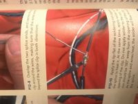
Strip more insulation off the single wire and then double it over.
This is in the Mack truck training book on electrical & electronics, It's an approved method. Works well too.
Step down or multi wire ****'s are also a good option.
FigureItOut
Well-known member
There's some good advice given, but this is actually a difficult question, I'm not sure the "right way" exists. If the doubling up method is indeed recommended by Mack, that lends some legitimacy to my own line of thinking on this. I frequently consult the AWG charts when doing things like this, if you find the actual cross-sectional area for a given wire gauge, you can double it and use a connector for the wire gauge that corresponds.
Other than the X&Y connectors listed, which I find to be oddly made and not useful, I've only seen one connector actually designed for this. These have a uniform wall thickness unlike most step-down connectors, and are lined with a special heat melt adhesive that is more viscous, allowing it to flow better between wires, where normal heat melt adhesive would leave a gap.
There are 3-way adapters for standard .25" and bullet connectors also. I've used these insulated 3 way bullet connector adapters and these non-insulated 3 way .25" adapters, both made by Molex.
The adapters have the limitation that they're designed for non-permanent connections, and in the case of the bullet style, they're expensive. The 2-into-1 heat shrink connectors are also expensive, and only work if all 3 wire ends are the same gauge.
I'm guessing you're doing aftermarket electronics? The industry standard and MECP recommended practice is to strip away some insulation from the middle of your "source" wire, without cutting it. Then with a pick tool separate the strands in the middle. Poke the stripped end of your new wire into the hole and wrap it around, alternating the wrap from one side of your new wire to the other. Then you'd solder the joint, insulate, and use proper vibration and abrasion mitigation methods as needed.
I think that the only "right" way to do what you're talking about, is probably to use a bus bar, though there are lots of "good" ways posted here. There are even more bad ways, that are practiced all the time and sworn by, probably without ill effect in most cases.
Last edited:
The most common mistake I see on splices is people tend to twist the wires. Makes an ugly joint that is tough to solder.
You need to do something to mechanically join the wires before soldering. Relying on just the solder to hold wires together is a bad idea.
The wire should at least be looped around if not twisted.
buffalobill
Well-known member
Lol. If your solder connection, and wire leading to an from that connection gets that hot, you've got other problems that are far more serious than melting solder. Lol. Like, the rest of your car burning down.
And wire nuts? You cant be seroius? Please don't make comments or suggestions on topics that you clearly don't know much about. Wire nuts are never a recommended connection in automotive wiring. Never.
One of the back of our dump trucks at work was a birds nest of wire nuts, scotchloks, and mismatched wire. I'm no electrician, but I hate stuff like that. Do it right or don't touch it!
HighPlainsWrencher
Well-known member
- Joined
- Jun 10, 2013
- Messages
- 218
I get mine from Caterpillar. They are pre built Y's and come assembled with a deutsch pin and two sockets. I cut them off and put what I need on. You can get them in various gauges and colors I believe although I usually only get yellow 16 gauge. I haven't been able to find the OM on the Y's so I think it is something that Cat builds themselves.
Roberts210
Well-known member
Ditto solder. Rosin core. I've used it for 35 years in more than a few cars and truck restorations, adding accessories, wiring lights and heater motors and extra horns, etc. etc. and have never had a problem. Don't use too much solder tho. Too much will weigh the joint down, it will start bouncing with the bumps and eventually break a wire right next to the joint.
bas157
Well-known member
So how do you make sure the connection is weather-resistant/waterproof for split in-line connections?
The one wire IN isn't the problem, but what about the two wires OUT?
Would heat-shrink tubing with the sealing glue stuff inside be sufficient?
I've been looking into this also as I want to tap into the reverse light wire on my truck to power two LED lights for backup lights.
I was looking at products from https://www.posi-products.com/index.html but the in-line ones only look like they are for one wire , not for splitting from 1 into 2. The posi-tap that aberdale posted looks like it would work, but how to keep the weather out of it? Would liquid electrical tape work OK? Seen that stuff, but never used it. My Grand Prix uses posi-twists hooked up to the blower motor and they seems like a good product.
plinker
Well-known member
The multi wire connectors have a longer shrink tube ends on the connector so it provides extra glue for sealing. A regular type connector or step down could be used with another piece of shrink tube added over it. Liquid electrical tape would also work to seal it as well, it works great for other concerns (nicks, ete..), but may look funny/sloppy.
There's some good advice given, but this is actually a difficult question, I'm not sure the "right way" exists. If the doubling up method is indeed recommended by Mack, that lends some legitimacy to my own line of thinking on this. I frequently consult the AWG charts when doing things like this, if you find the actual cross-sectional area for a given wire gauge, you can double it and use a connector for the wire gauge that corresponds.
Other than the X&Y connectors listed, which I find to be oddly made and not useful, I've only seen one connector actually designed for this. These have a uniform wall thickness unlike most step-down connectors, and are lined with a special heat melt adhesive that is more viscous, allowing it to flow better between wires, where normal heat melt adhesive would leave a gap.
There are 3-way adapters for standard .25" and bullet connectors also. I've used these insulated 3 way bullet connector adapters and these non-insulated 3 way .25" adapters, both made by Molex.
The adapters have the limitation that they're designed for non-permanent connections, and in the case of the bullet style, they're expensive. The 2-into-1 heat shrink connectors are also expensive, and only work if all 3 wire ends are the same gauge.
I'm guessing you're doing aftermarket electronics? The industry standard and MECP recommended practice is to strip away some insulation from the middle of your "source" wire, without cutting it. Then with a pick tool separate the strands in the middle. Poke the stripped end of your new wire into the hole and wrap it around, alternating the wrap from one side of your new wire to the other. Then you'd solder the joint, insulate, and use proper vibration and abrasion mitigation methods as needed.
I think that the only "right" way to do what you're talking about, is probably to use a bus bar, though there are lots of "good" ways posted here. There are even more bad ways, that are practiced all the time and sworn by, probably without ill effect in most cases.
I like Those 2-1 connectors in your link. I've never seen them but they seem like a great option for what the OP is asking for.
I would second your opinion on the poke, wrap, and solder technique. When I was a pro 12v installer, I probably did that 10,000+ times for remote start and security installations. Cheap, effective, and reasonably fast with the right tools.
ca90ss
Well-known member
So how do you make sure the connection is weather-resistant/waterproof for split in-line connections?
The one wire IN isn't the problem, but what about the two wires OUT?
Would heat-shrink tubing with the sealing glue stuff inside be sufficient?
It's been my experience that the heat shrink **** connectors don't seal well enough around two wires to be waterproof. The most reliable solution I've come up with so far is to fill the connector with dielectric grease.
SantaAna12
Well-known member
- Joined
- Mar 1, 2012
- Messages
- 1,091
It's been my experience that the heat shrink **** connectors don't seal well enough around two wires to be waterproof. The most reliable solution I've come up with so far is to fill the connector with dielectric grease.
Interesting. What connectors have you been using?
Edit: NVM. I take it u referring to two wires into an opening designed for one.
Yeah I hear you. I have done it and will again.....depending on the application. But not even approaching a load factor or application that concerns.
I probably dont have to say this: if ur splices/connections are generating significant heat?
Take a different approach.
Last edited:
theoldwizard1
Well-known member
Retired automotive engineer. For many, MANY years the auto industry "standard" for an inline splice was as follows:
This is a highly water resistant connection.
If you are doing a lot of wiring do yourself a favor and buy MARINE wire. Each individual strand in tinned with solder. This makes it almost impervious to corrosion.
- Remove about 1"-2" of the insulation on the running wire
- Remove about 1" of the the wire to be spliced in
- Wrap the wire to be spliced in wire at least 1-1/2 times over the running wire
- Wrap with "friction" (cloth based) tape at least 3 wraps
- Wrap the whole assembly with "harness" tape (PVC electrical tape with NO adhesive).
- Finish the harness tape end with 3 wraps of friction tape.
This is a highly water resistant connection.
If you are doing a lot of wiring do yourself a favor and buy MARINE wire. Each individual strand in tinned with solder. This makes it almost impervious to corrosion.
You can buy splice crimps to solder in. Right out of the textbook lol
This is how GM has been doing it for many years. They then cover the joint with some thick black fibery tape, almost like black gorilla tape. This is only inside the vehicle, outside is always into a weather pack connector.
MikeF2316
Well-known member
This is how GM has been doing it for many years. They then cover the joint with some thick black fibery tape, almost like black gorilla tape. This is only inside the vehicle, outside is always into a weather pack connector.
I've seen newer cars with a "one in many out" connections in wiring harnesses, specifically for bulbs that light up multiple small things, like seat belt buckles, ash trays, switches etc. The ones I've seen use a single uninsulated crimp and the resulting connection covered with a heavy, very sticky cloth tape. But only inside the car, not under the hood, or underneath.
sberry
Banned
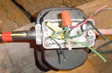
I have done my share of this and replaced a lot of stuff "done right" Heat shrink **** that holds more water than it keeps out. I have used hundreds, maybe 1000's of wire nuts and a tight one doesn't vibrate loose, they use them on machines that do and very little auto wire actually vibes. They have been used filled with silicone and in anywhere covered and oriented like a hat where we take the straw with penetrating spray and blast a shot in they last untill taken apart. we use them in jboxes under truck bumpers, just did a demo to one was in service 30 years where the connector was sprayed and inside of box sprayed a little before being covered and the connections looked near new. I can't ever recall a nut coming loose.
Attachments
Last edited: