OccupantRJ
Well-known member
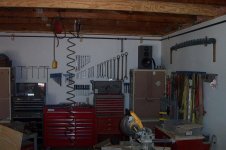
I have been working on the air compressor piping for my shop for a while now, installing as I got the time and inclination. The system is feeding two media blasting cabinets, providing general shop air through 7 drops, and providing two external through the wall outlets for outside use, one on each side of the shop. These will come in handy for pot sandblasting.
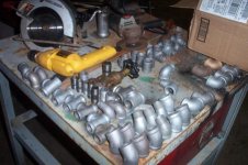
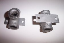
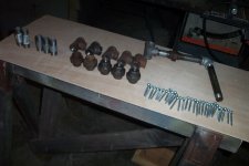
I had accumulated about a hundred pounds of various new and used black and galvanized pipe fittings throughout the years at auctions and sales, so I used what I had on hand. There is a mix of black and galvanized. The used fittings were wiire brushed or beadblasted before use. The black piping for the runs was purchased locally from the big box.
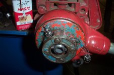
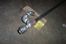
The system will ultimately be fed by two 20 CFM compressors, but right now one vertical is in a disassembled state, due to having to move it. The flex hose is 1 inch rated at 300 psi. I cut a 3/4 ****** in two, machined barbs on the OD of it, then used them to attach the flex hose with double clamps. This gives maximum flow at this area, as the ID of the hose is larger than the ID of the pipe. The main trunk is 3/4" black pipe, which drops in size to 1/2" after passing the blasting cabinets.
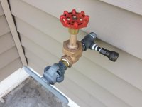
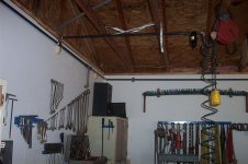
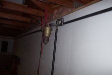
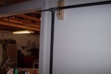
After leaving the compressor, the piping supplies a through the wall external outlet, a second compressor inlet, then rises and pitches upward until it passes through the wall, then goes vertical to a T. After the T, the piping then slopes away from the compressor on the rest of the runs.
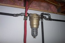
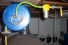
Condensate drains with quarter turn ball valves are provided at the drops and low points of the system. A 3/4" moisture separator is installed on the main trunk right before the first blasting cabinet, then the cabinet has it's own 1/2" unit and pressure regulator. The large cabinet is directly connected until I can round up another individual separator for it also.
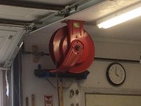
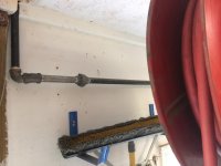
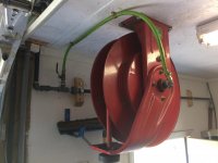
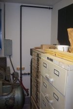
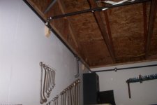
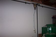
I was forced to go up and over the garage door through the attic because of the direction the piping needed to take to reach it's end point. That section of line will be insulated. There are drip legs provided on each side of the doorway.
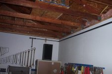
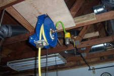
The line then passes through another wall into the machining room to provide nozzles for swarf, bandsaw blade blowoff air, and an external outlet on that side of the shop. You can see that some shop's piping requirements are not as simple as others. This system will be used to make extra cash after retirement by media blasting.
By following the picture sequence, you can see how the piping was fitted in somewhat relative order of assembly and installation.
I had accumulated about a hundred pounds of various new and used black and galvanized pipe fittings throughout the years at auctions and sales, so I used what I had on hand. There is a mix of black and galvanized. The used fittings were wiire brushed or beadblasted before use. The black piping for the runs was purchased locally from the big box.
The system will ultimately be fed by two 20 CFM compressors, but right now one vertical is in a disassembled state, due to having to move it. The flex hose is 1 inch rated at 300 psi. I cut a 3/4 ****** in two, machined barbs on the OD of it, then used them to attach the flex hose with double clamps. This gives maximum flow at this area, as the ID of the hose is larger than the ID of the pipe. The main trunk is 3/4" black pipe, which drops in size to 1/2" after passing the blasting cabinets.
After leaving the compressor, the piping supplies a through the wall external outlet, a second compressor inlet, then rises and pitches upward until it passes through the wall, then goes vertical to a T. After the T, the piping then slopes away from the compressor on the rest of the runs.
Condensate drains with quarter turn ball valves are provided at the drops and low points of the system. A 3/4" moisture separator is installed on the main trunk right before the first blasting cabinet, then the cabinet has it's own 1/2" unit and pressure regulator. The large cabinet is directly connected until I can round up another individual separator for it also.
I was forced to go up and over the garage door through the attic because of the direction the piping needed to take to reach it's end point. That section of line will be insulated. There are drip legs provided on each side of the doorway.
The line then passes through another wall into the machining room to provide nozzles for swarf, bandsaw blade blowoff air, and an external outlet on that side of the shop. You can see that some shop's piping requirements are not as simple as others. This system will be used to make extra cash after retirement by media blasting.
By following the picture sequence, you can see how the piping was fitted in somewhat relative order of assembly and installation.
Attachments


Last edited:


")
 Have an old Quincy 325 compressor, and most of the plumbing parts now, so just need to plan it and do it!