To avoid these ads, REGISTER NOW!

Saylor-Beall 705 Compressor

AntonyJ1214

Active member
Joined
Sep 8, 2014
Messages
33
Location
Hampton, VA
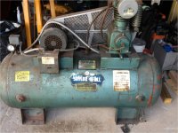
This is the compressor that was in my house when I bought it a couple months ago...


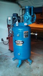
I had to get some work done to it because the pressure switch was leaking and I wanted to get it all cleaned up... so I took off the pressure switch (which I believe is a Square D pressure switch but not positive) and I noticed that it has another switch on the side of it that has a line running from the motor to the after cooler. Is that the overload switch? I took it off and cleaned it out because it was all gunked up with oil and crud. When I finished cleaning it and giving it a small make over I put it back together without the switch. Here it is without the pressure switch installed and wired up.


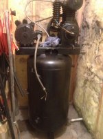
You can see that the line goes strait from the motor to the after cooler. Is that 2nd switch necessary or can I leave it off?
 
To avoid these ads, REGISTER NOW!

EOC_Jason

Well-known member
Joined
Jun 25, 2012
Messages
11,388
Location
Bentonville, AR
The copper line going to your pressure switch will usually vent when the power kicks off. But on the other hand I've never seen the unloader line run to the after-cooler like that. I have no idea wtf the person was doing.

Probably best to contact Saylor Beall, see if they have a manual online or can send you some info on how that is supposed to be piped up...
 
OP
A

AntonyJ1214

Active member
Joined
Sep 8, 2014
Messages
33
Location
Hampton, VA
Probably best to contact Saylor Beall, see if they have a manual online or can send you some info on how that is supposed to be piped up...

Yeah I have contacted them and they sent me the manual from the compressor. Its an early to mid 80s model so theres not much to it. Im gonna go through it and see if there is anything about it. When I look at pictures of the compressor on google I dont see anything like what is set up on my compressor... It just looks weird to me.
 

Trey T

Well-known member
Joined
Aug 3, 2011
Messages
3,749
Location
Houston, TX
Regarding the exit/discharge hook up, the first picture is correct. If you leave it as it, like in second photo, it will pump but very weak (assuming the exit/discharge is vented, which is moronic). For the unloader, that will work better than unloading it at the tank.

I would try to hook up the way they had it in first photo.
 
OP
A

AntonyJ1214

Active member
Joined
Sep 8, 2014
Messages
33
Location
Hampton, VA
The only thing I have changed on the compressor setup is removed whatever switch was mounted to the side of the pressure switch that had the platic line from the compressor and aftercooler. In the second picture the pressure switch isnt installed. I think I need to unmount the compressor and the motor and switch them around. That way the fill line for the tank is in the center vice facing the outside and it doesnt have to come clear over the top of the compressor then down.
 

EOC_Jason

Well-known member
Joined
Jun 25, 2012
Messages
11,388
Location
Bentonville, AR
Yes, that is another problem... I would switch them too if it is possible. That doesn't look like the original tank. There might not be adjustments to move the motor on the other side.
 
OP
A

AntonyJ1214

Active member
Joined
Sep 8, 2014
Messages
33
Location
Hampton, VA
Yeah thats true too... I may just see if I can re-run a different line or something from the compressor to the tank. That one just looks weird. The mount on the tank has some long holes cut out in it to be able to mount different compressors/motors on it. Im gonna look into that today when i get home. It may be set up that wayt because of not being able to mount it on the other side.
 

RABRods

Well-known member
Joined
Nov 5, 2011
Messages
110
Location
SE, Michigan
My Saylor Beall definately has a different setup. The line from the front is the unloader and runs to the check valve on the tank. The intercooler has a relief valve no line connected to the intercooler.
 

Attachments

  • Picture4.jpg
    Picture4.jpg
    142.3 KB · Views: 76
  • Picture9.jpg
    Picture9.jpg
    142.9 KB · Views: 67

EOC_Jason

Well-known member
Joined
Jun 25, 2012
Messages
11,388
Location
Bentonville, AR
I would assume there is a tank check valve on his setup. If not you can get them pretty cheap from eBay or other places... I would run it like it's supposed to be, having it tied into the aftercooler just doesn't look right.
 

C96

Well-known member
Joined
Nov 30, 2013
Messages
1,251
Yeah I have contacted them and they sent me the manual from the compressor. Its an early to mid 80s model so theres not much to it. Im gonna go through it and see if there is anything about it. When I look at pictures of the compressor on google I dont see anything like what is set up on my compressor... It just looks weird to me.

You have the manual now, so connect it as it shows. Stop trying to second guess the manufacture.
 
OP
A

AntonyJ1214

Active member
Joined
Sep 8, 2014
Messages
33
Location
Hampton, VA
There has been no second guessing of the manufacturer but I really don't see anything in the manual of that particular line, but I'm still reading


Sent from my iPad using Tapatalk
 

C96

Well-known member
Joined
Nov 30, 2013
Messages
1,251
Here is an actual Saylor-Beall drawing showing the bleeder tube you are inquiring about.

Hope this helps.

t86hc4qnm58mg6bc0t1c1hute5_pg.15_1.jpg
 
OP
A

AntonyJ1214

Active member
Joined
Sep 8, 2014
Messages
33
Location
Hampton, VA
Okay so how interpret that is that the tube connects to some fitting that is also connected to the line that fills the tank... Which I don't have that fitting. Also its set up in that picture 180 degrees from how mine is... Hmmm interesting
 

C96

Well-known member
Joined
Nov 30, 2013
Messages
1,251
Yes, it’s the tank check valve. The check valve is configured with a side fitting that accepts the bleeder tube coming from the unloader valve.

S-BBleederTube_zpscfcf85dd.jpg
 
To avoid these ads, REGISTER NOW!

EOC_Jason

Well-known member
Joined
Jun 25, 2012
Messages
11,388
Location
Bentonville, AR
It's still venting (I hope), just not in the right place. I don't even know why they put those big NPT fittings on their aftercoolers like that.
 

DekeT

Well-known member
Joined
Aug 12, 2011
Messages
2,234
Location
USA
so what purpose does the tube on mine have? Going from the front of the compressor to the aftercooler?

It's not a problem to keep it hooked up the way it is. The factory hookup unloads air from the exhaust of the high compressor cylinder. A previous owner hooked up a system to unload the pressure from the low pressure side of the compressor. I don't see anything wrong with that. In fact I think it is a good idea as there is probably as much air in the aftercooler as in the HP exhaust line. I would keep a pressure relief valve in for the aftercooler though. The line going to the aftercooler may have originally been to connect to unloader valves on the cylinder head that were used for continuous operation.
 
OP
A

AntonyJ1214

Active member
Joined
Sep 8, 2014
Messages
33
Location
Hampton, VA
Interesting... Im gonna go home and snap pics of how everything is set up and where the relief valve is and make sure Im going about this the right way. This is my first big air compressor and I really dont have the money to replace it if it goes out. I appreciate all the help. Im also going to look into switching the sides of the motor/compressor so the fill line will face the inside vice the outside. May just turn it around and reverse the direction of the motor too... guess thats an option if the holes on the base dont line up on the other side.
 
OP
A

AntonyJ1214

Active member
Joined
Sep 8, 2014
Messages
33
Location
Hampton, VA
So I have been looking at other threads here and I have noticed the picture I have attached. The aftercooler is on the right side of the compressor unlike mine where its on the left. Can the aftercooler and the discharge line be switched?
 

Attachments

  • image.jpg
    image.jpg
    142.5 KB · Views: 54
  • 66657bc28212724ab5bfe0d4405810fe.jpg
    66657bc28212724ab5bfe0d4405810fe.jpg
    90.6 KB · Views: 49
Last edited:
OP
A

AntonyJ1214

Active member
Joined
Sep 8, 2014
Messages
33
Location
Hampton, VA
Just wanted to see if it was something that I could just take off the discharge line and the aftercooler and switch them... would save me from having to take the compressor off and motor off to switch them to put the discharge line to the middle vice the outside.
 
OP
A

AntonyJ1214

Active member
Joined
Sep 8, 2014
Messages
33
Location
Hampton, VA
So can anyone tell me if I can take that intercooler assembly off the left side and move it to the right? I contacted Saylor Beall and they referred me to a local place that wants to charge me to come out and look at the compressor.
 
OP
A

AntonyJ1214

Active member
Joined
Sep 8, 2014
Messages
33
Location
Hampton, VA
Yeah I just went out and looked at it. There's no way it could be switched. The connections are completely different. If I'm gonna get the discharge to the other side I'm gonna have to take it off and turn it around and reverse the direction of the motor. I need to order one of the check valves that go on the tank so I can connect unloaded to the tank instead of the intercooler like it is now...
 

Carla

MEMBER EMERITUS
Joined
Nov 27, 2010
Messages
672
Here are a couple photos of my Saylor-Beall 705, which has been in service since being put in as a reconned unit in 1989, and was pulled down for 'preventive maintenence' rings and rod bearings (valves were still good) two years ago.

The rings and rod bearings were just showing a bit of wear, the bores and crank-pins were unworn, still within 'new machine' tolerance. (personally, I think its 'cheap at the price' to replace rod bearing inserts before they might have worn enough to start damaging the journal finish on the crank-pins)

It has been reliable, sometimes running for 10 to 12 hours continuously, in the summer heat here in Cali, feeding a glass-blast cabinet.

Here are photos which show the correct plumbing for the unloader, and show the safety relief valve on the intercooler.

Note that the finned casting is an 'intercooler' which receives the low-pressure air from the LP piston discharge valve, and delivers it to the HP piston suction valve, thence, of course, to the HP piston.

An 'aftercooler' would be 'down-stream' of the HP discharge valve, to cool the air after it has left the pump.

Note the small 'air muffler' in the discharge port of the unloader. I tapped that port for 1/4" NPT, and fitted the muffler to avoid the 'sharp hiss' sound as the pump stops, and the unloader valve dumps the air between the HP discharge valve, and the tank check valve, to atmosphere. The unloader valve on a S-B is a tiny little thing, like a tire tube valve, operated by the four centrifugal weights in the 'unloader housing' on the exterior of the crankcase. (there is an adjustment for this valve, which must be set correctly)

Note, in my particular application, the 'intake silencer', which is nothing more than a new-old-stock WW2 military Jeep muffler, with a filter adapter made from two little round plates of aluminium, to hold an 'off-the-shelf' carburetter air cleaner element, for some smallish car. (dunno which make/model of car, I just selected the element as being of a suitable size)

I had a helper put insulation in the walls near the compressor, and cover the walls with acoustical tile.....which, at least, somewhat moderates the noise level of the unit.

if someone who is better with the computer than I could post the photos, I'd appreciate..... : )

cheers

Carla

www.tactical-link.com/cpix/sbcomp1.jpg
www.tactical-link.com/cpix/sbcomp2.jpg
 
Last edited:

Carla

MEMBER EMERITUS
Joined
Nov 27, 2010
Messages
672
So can anyone tell me if I can take that intercooler assembly off the left side and move it to the right? I contacted Saylor Beall and they referred me to a local place that wants to charge me to come out and look at the compressor.

Saylor-Beall offers that pump in both 'right-hand' and 'left-hand' versions, as a factory option, so that the discharge port is in the most convenient location for the tank plumbing to be used with the variety of tank the user selects.

This is done by making two versions of the compressor head, which are 'mirror-image', so to speak.

You could, indeed, change the position of the discharge port, but only by purchasing an 'opposite-hand' pump head casting from S-B, which is 'not cheap' (I called S-B to ask about this item, on a 705 pump I rebuilt for a friend, which had piping running around the head, an improvisation when the original tank was replaced.)

cheers

CArla
 
Last edited:
OP
A

AntonyJ1214

Active member
Joined
Sep 8, 2014
Messages
33
Location
Hampton, VA
Yeah but I can also turn the pump 180deg and then reverse the direction of the motor... I would think that would work just as well correct?
 

BJ42LX

Well-known member
Joined
Dec 29, 2010
Messages
2,811
Location
WNY
If you turn the pump around then the pulley will be on the front and the motor will have to be rotated too. If you rotate both you won't have to reverse the motor.

PS: as a guy jumping into this thread today: why wouldn't you just replace the leaky pressure switch, clean it up and use it for another 30 years. I don't understand why you want to re-route control lines and eliminate switches and valves.:confused::confused:
 
Last edited:
OP
A

AntonyJ1214

Active member
Joined
Sep 8, 2014
Messages
33
Location
Hampton, VA
I did clean everything up and fix the pressure switch. I was just looking at the fact that the discharge line is one the outside and whoever put thing thing together basically rigged up some piping to route it over the top of the compressor. Just a clean up attempt. I mean it works... not complaining. I do however need to get the unloader line done properly. It wasnt set up right from the start. It was routed to some switch that was attached to the pressure switch. Im sure what they were going for with the way they had it set up. Basically there was a line coming from the intercooler assembly going to one side of a switch then the other side of the switch had a line coming from the unloader port on the compressor. The switch was tripped when the air compressor was shut down by the pressure switch. Not sure where it vented if it vented at all.... I donno. I just want to make sure its setup properly so i can get as much life out of this compressor as I can. Cant afford a new one haha.
 

Carla

MEMBER EMERITUS
Joined
Nov 27, 2010
Messages
672
I did clean everything up and fix the pressure switch. I was just looking at the fact that the discharge line is one the outside and whoever put thing thing together basically rigged up some piping to route it over the top of the compressor. Just a clean up attempt. I mean it works... not complaining. I do however need to get the unloader line done properly. It wasnt set up right from the start. It was routed to some switch that was attached to the pressure switch. Im sure what they were going for with the way they had it set up. Basically there was a line coming from the intercooler assembly going to one side of a switch then the other side of the switch had a line coming from the unloader port on the compressor. The switch was tripped when the air compressor was shut down by the pressure switch. Not sure where it vented if it vented at all.... I donno. I just want to make sure its setup properly so i can get as much life out of this compressor as I can. Cant afford a new one haha.

Seriously......just re-read posting #16 in this 'thread'

That is the original factory setup, and is the correct setup for this model of pump.

If you want your compressor to run well, just follow the factory instructions for setting it up.....it really is that simple.....and easy......

If the check valve on the tank you now have doesn't have the 1/8 NPT tapped hole for the 'bleed-off' unloader line, then you really must replace it with one which does. The necessary copper tubing and fittings should be available 'off-the-shelf' at any good industrial supply house or most automotive suppliers.

Having a 'wrong hand' pump is no real problem, other than an aesthetic issue with the pipe or tubing from the discharge port of the head running around the pump to the tank check valve. This additional length of pipe or tubing will not adversely affect or restrict the air delivery.

The only thing which should be in the tapped hole in the intercooler is a safety valve. You can get a new intercooler safety valve from Saylor-Beall, relatively inexpensively.

It might be prudent to fit a new safety valve to the tank, just as a precaution.

As you can see in the photo of my S-B compressor, the only thing needed for the pressure switch is that it be plumbed to the tank, and wired to the mag-starter for the motor.

What may be confusing is that some pressure switches are provided with a valve system to also act as an unloader, opening a port to atmosphere to 'bleed-off' the pressure in the line between the pump and the tank.

The S-B 705, having a centrifugal unloader system of its own, does not need this form of unloader at the pressure switch.

cheers

Carla
 
To avoid these ads, REGISTER NOW!
Top Bottom