To avoid these ads, REGISTER NOW!

Show off your sheet metal fab projects

Boiler

Well-known member
Joined
Nov 20, 2009
Messages
1,967
Location
Indiana
This is an aluminum off-road bumper I made with a guy I work with. I did the design, we both made parts, he welded it, and we both finished it. Finally it was powdercoated. Not the greatest paint surfaces...we're used to round tube that hides a lot more. Turned out pretty good I think. I've got about 5 people that are waiting for me to make them one after I finish tweaking the design.

IMG_1623.jpg

IMG_1622.jpg

IMG_1624.jpg

IMG_1625.jpg

IMG_1627.jpg

IMG_1628.jpg

IMG_1639.jpg

IMG_1621.jpg

IMG_1635.jpg

IMG_1631.jpg

IMG_1646.jpg

IMG_1645.jpg
 
To avoid these ads, REGISTER NOW!

blue dog

Banned
Joined
Jul 4, 2010
Messages
4,051
Location
Culver City Ca.
I dig your bumpers Boiler. Most have no idea the time it takes to do this. Are these steel or aluminum ?
They are very clean. do you build winch bumpers for the front ?
 

Boiler

Well-known member
Joined
Nov 20, 2009
Messages
1,967
Location
Indiana
I haven't done a front bumper yet.

The bumper mounts to the uni-frame where the tow package normally mounts, with 3 x 3 x 3/8 tk aluminum angle, with a partial added flange making it a c-channel. There are tubes connecting them (for hitch option only) that are 3x2x1/4 wall rectangular aluminum, and the reciever itself is 3" sq x 1/2" wall (try finding stock in that...). Finally 95% of the rest is 1/4" aluminum plate. Everything is 6061-T6.

The way I do these things (I do roof racks too) I have to determine the geometry of the jeep, convert that to cad, then design the item to fit it. Then I design a fixture to build it on. When I'm done, it fits great (hopefully) and its repeatable without building to fit every time.

We had about 20 hours in measuring what we were building around, I had about 120 hours in CAD for the design and fixture & drawings. Then we had the goofy parts waterjet cut and we made the rest. Total fabrication from drawings was probably 30 hours, including head scratching, corrections etc. Basically I worked on it for about 3 hours a night from Feb 1st thru june 1st. Been very tough to get motivated to make the corrections....

You can see that we had some warpage drawing the outside ends down if you look directly on the rear. It caused some weird fitting with the fender flares and such because we really had no way to correct it. My friend that welded it took it out of the fixture after tacking it to make the interior welding easier. I could have killed him. Next time every piece will remain bolted to the fixture until its 95% welded & cooled, and hopefully we reduce that warpage considerably. I'm also modifying the way the parts are made to alleviate some of that, and we're going to play with the weld order to help too.
 
Last edited:

NASTYZEN

Well-known member
Joined
Jun 11, 2010
Messages
2,823
Location
St-Colomban,Que. Canada
Got a question for you fabrication guys, What does it take to get an apprenticeship in fabrication shop that does classic cars or anything close to it?
Or a restoration shop.There is fabrication shops all over south florida, but very few for classic cars.
:fingersx:

First thing is to get the basic skills like welding and mechanical and lots of determination.The way I got into racing was by hanging around the tracks and offering free help.Once people see you are dedicated and hard working,it makes it easyer to justify training someone.
 

blue dog

Banned
Joined
Jul 4, 2010
Messages
4,051
Location
Culver City Ca.
Boiler, if you built bumpers for jeeps side from the Liberty, i bet you could make a living at it. Quality bumpers for the trail rig guys are not cheap.
 

ZTFab

Well-known member
Joined
Jan 6, 2008
Messages
397
Location
Upland, CA
Here are some aluminum dash's that I've made for some Polaris RZR's and an R1 powered Yamaha Rhino.

All were hand formed 3003 .050" aluminum. Tig welded and blended.

IMG_1524.jpg


IMG_1529.jpg


IMG_1538.jpg


IMG_1541.jpg


IMG_1600.jpg


Another one:

IMG_1914.jpg


IMG_2040.jpg


IMG_2045.jpg


IMG_2056.jpg


IMG_2055.jpg


IMG_2049.jpg


IMG_2143.jpg
 

LIVELY

Well-known member
Joined
May 8, 2010
Messages
362
Location
Illinois
GREAT WORKMANSHIP:beer:
is it powdercoated or painted when done?
panels still removable?
average time constructing the dashes?
nice:bounce::bounce:
 

ZTFab

Well-known member
Joined
Jan 6, 2008
Messages
397
Location
Upland, CA
GREAT WORKMANSHIP:beer:
is it powdercoated or painted when done?
panels still removable?
average time constructing the dashes?
nice:bounce::bounce:

Thanks. :beer:

They are all powdercoated.

All panels are still removable with the DZUS fasteners.

anywhere from 20 to 60 hours.
 

LIVELY

Well-known member
Joined
May 8, 2010
Messages
362
Location
Illinois
i really like fabs like you do
you got any other forming pics? -that you would share--if you don't i understand

did you weld completely or how did you get smooth joints?:headscrat
 

ZTFab

Well-known member
Joined
Jan 6, 2008
Messages
397
Location
Upland, CA
i really like fabs like you do
you got any other forming pics? -that you would share--if you don't i understand

did you weld completely or how did you get smooth joints?:headscrat

I form the radius edges like this.

Make flat patterns of the part
I then "tip the edge" of the sheet metal with my bead roller equipped with a "tank roll" die
The I use a hammer and T-Dolly to finish the radius.

On most of these parts I will actually form the full radius on one side of the piece and leave the mating piece completely flat, others I will form half of the radius on each part and then join them.

It depends on how big of a radius you are trying to achieve.

Here is a pic of how it looks when I get the parts formed and tacked. From here I weld them completely, hand planish the welds with a body hammer, and then grind/sand away the excess, then finish with a DA sander.

IMG_1912.jpg


I use the same technique when I build the LED enclosures:

IMG_1852.jpg
 

ZTFab

Well-known member
Joined
Jan 6, 2008
Messages
397
Location
Upland, CA
How about some pics of the whole machine at once?

No problem!

Here is the one with the black dash: 2009 Polaris RZR S

ZTFab-Polairs-RZR-10.jpg


IMG_1671.jpg


The one with the Gray dash: 2009 Polaris RZR S

IMG_2064.jpg


IMG_2066.jpg


IMG_2139.jpg


IMG_1955.jpg


The one with the Orange dash: Yamaha Rhino with R1 motor

IMG_2439.jpg
 

ZTFab

Well-known member
Joined
Jan 6, 2008
Messages
397
Location
Upland, CA
Both RZR's are the stock Polaris 760cc HO Twin cylinder engine with just an intake and exhaust.

They make 51~ horsepower and push these little cars to just under 65mph.

The Rhino on the other hand has a 1000cc Yamaha R1 street bike engine shoved in it with an RPM FNR diff unit and is chain driven utilizing the R1 6 speed trans.

The motor has been upgraded and tuned to 180HP and the car weighs 1500lbs.
It was clocked in Ocotillo Wells on GPS just shy of 100mph with another gear to grab.
 

ZTFab

Well-known member
Joined
Jan 6, 2008
Messages
397
Location
Upland, CA
Here's some more work from the R1 Rhino.

I had to redo the rear shock mounts since the guy that built the chassis didn't know how to.

All pieces were either hand cut on my band saw or on my shear and dimpled using my JMR dimple dies. The shock tabs are 3/16" CRS and are TIG welded. The shock mounts and cross brace are all 11ga CRS are MIG welded.

The Shock mounts:

IMG_2409.jpg


IMG_2406.jpg


IMG_2394.jpg


IMG_2396.jpg


The Shock Tabs:

IMG_2411.jpg


IMG_2404.jpg


IMG_2402.jpg


IMG_2405.jpg


The Cross Brace:

IMG_2418.jpg


IMG_2419.jpg


IMG_2420.jpg


IMG_2423.jpg


IMG_2425.jpg


IMG_2429.jpg
 
To avoid these ads, REGISTER NOW!

afazz

Well-known member
Joined
Nov 25, 2007
Messages
860
Location
Pittsburgh, PA
Holy **** those welds are perfect! I'm not on that level, but here's some work I'm doing to my VW.

I'm cleaning up the engine bay, it's a show car. Here are some pics of my reworking and shaving of the firewall.

before:
DSCF0923.jpg


121010Reshaped.jpg


dsinsert.jpg


I had to turn a new set of dies for the bead roller to match the depth of the OEM flange.
rollerdies.jpg


DSCN0068.jpg


DSCN0084.jpg


DSCN0085.jpg


Tonight I threw some primer on to see how it's shaping up.
DSCN0106.jpg


The remaining holes aren't getting shaved, but the insert bolts will be plug welded and ground smooth.
 

e-tek

Well-known member
Joined
Dec 19, 2007
Messages
10,690
Location
Saskatoon, SK
ZTfab - ARTIST IN THE HOUSE!!! Holy **** now THAT's Fab work...and welding!! thanks for showing off your work. Now I want a rad-ATV too!
 

MP&C

Well-known member
Joined
Oct 21, 2009
Messages
4,396
Location
Leonardtown, MD
Disecting & fabricating on a rusty wagon tail gate. the outer skin looked fairly decent for 55 year old metal, a couple pin holes showing....

Picture547.jpg


Picture544.jpg


Picture545.jpg


Picture546.jpg


The major issue with these tail gates, due to how they lean forward, any water collecting inside lays in the inner panel....

Picture548.jpg


.......as you can see from the rear....

Picture549.jpg


We laid out the proposed cut lines, used holes in the inside corners to add a radius, and made some sparks...

Picture554.jpg


Picture555.jpg


Picture557.jpg


The tailgate has some internal stiffeners to help support the loading and unloading, and they have suffered some damage as well....

Picture559.jpg


Picture560.jpg


Picture561.jpg


Since they're just spot welded in, and it will be easier to weld in newly fabricated ones than attempt repairs of the rusty ones in place......

Picture572.jpg


Picture574.jpg


We'll need to unfold some flanges to remove the rest of the inner skin....

Picture577.jpg


Picture578.jpg
 

MP&C

Well-known member
Joined
Oct 21, 2009
Messages
4,396
Location
Leonardtown, MD
Probably one of the biggest challenges in taking things apart for repairs is doing so without inflicting more damage. I had seen a recent post on pliers used to remove door skins, and thought they would come in handy here on the bottom of the tailgate.
This is why you never throw away Vice grips that have the worn off teeth that have just lost their bite. The lower jaw is modified to receive the edge of the door skin...

Picture582.jpg


Then a suitable "blade" is found....

Picture580.jpg


Picture583.jpg


Some welding and grinding, and we have a new body tool.....

Picture584.jpg


Picture585.jpg


Picture586.jpg


Starting at the corner, a diagonal slice is made in the inner panel so it will remove easier...

Picture579.jpg


....and the tool is used to gently pry up on the flange of the tailgate skin.....

Picture587.jpg


Picture588.jpg


Picture589.jpg


Spot welds were removed with a burr grinder, in an attempt to keep the damage (and hole diameter) to the skin flange at a minimum. Continuing:

Picture590.jpg


Picture592.jpg


Picture593.jpg


Picture594.jpg


Next we'll work on making replacements for these structural members:

Picture572.jpg


Picture575.jpg


Picture596.jpg
 

MP&C

Well-known member
Joined
Oct 21, 2009
Messages
4,396
Location
Leonardtown, MD
Fixing one of the rather "rotted" parts that came out of the tailgate. This actually serves as a bolting plate for the tailgate hinge, so it definitely is in line for replacement.

Picture595.jpg


Started with a piece of 16 gauge CRS and using the Wheeling Machine, prestretched the area for the stiffening bead.

Picture610.jpg


...and with bead...

Picture611.jpg


Picture612.jpg


The Neil Dunder tooling....

Picture613.jpg


A bend relief cut in the bead, panel bent, and welded...

Picture614.jpg


Picture615.jpg


Picture616.jpg


Missed a few in process pictures here, but using a piece of 3 x 3 square tubing as a die, a 2 x 2 as a punch, and a BABPH to apply pressure, a relief for the tailgate rib is formed.

Picture618.jpg


Trimming to size....(note 3 x 3 die in lower right corner)

Picture620.jpg


Needs holes drilled yet...

Picture622.jpg


Picture623.jpg


test fit....

Picture624.jpg


Alignment of hinge hole....

Picture625.jpg
 

MP&C

Well-known member
Joined
Oct 21, 2009
Messages
4,396
Location
Leonardtown, MD
Using some MDF for hammerforming the inner tailgate, the MDF is stacked to allow the flange to be folded downward.


Picture630.jpg


The first three layers are aligned and screwed down, then the 18 ga CRS and "locking" layer of MDF is screwed down, through the entire pile using 4" long screws. A slight flange is also folded at the bottom to help "lock" the bottom edge of the plate against the MDF and hopefully prevent any pulling. Don't think it is needed on the straight bends, but it may help toward the corners.


Picture631.jpg


Picture632.jpg


Flange width marked and trimmed. The corners are cleaned of any burrs that may promote cracks to form by using a 3/4" dia drum sander.


Picture635.jpg


Picture636.jpg


Straight bends are worked with a low crown hammer to start the profile........


Picture637.jpg


........and as the corners tighten, this was the most effective stretching device. Repeated overlapping rows made short work of the stretching..


Picture641.jpg


....and the door skin hammer was used around the perimeter to "sharpen" the bends...


Picture639.jpg


Picture640.jpg


With the first bend complete, the Lancaster shrinker is used along the folded flanges to match the crown of the tailgate skin.....


Picture643.jpg


Picture644.jpg


............here compared to the lower tailpan....


Picture647.jpg


Picture648.jpg


....to be continued
 
Last edited:

Orangestang

Well-known member
Joined
Dec 22, 2010
Messages
525
Location
Glendale ,AZ
MP&C Is body work what you do for a living? It all looks great. Or are you doing this on your own? Theres not enough hours in the day to do all that with a wife and kids,and if I did spend that much time in the garage I'd be in the dog house, I'm jealous LOL
 

MP&C

Well-known member
Joined
Oct 21, 2009
Messages
4,396
Location
Leonardtown, MD
At present its just a side gig, my nephew helps me as well. I do more rust repair than bodywork it seems......but I enjoy the challenge. And yes, I have experienced that dog house you speak of.....:lol_hitti
 

MP&C

Well-known member
Joined
Oct 21, 2009
Messages
4,396
Location
Leonardtown, MD
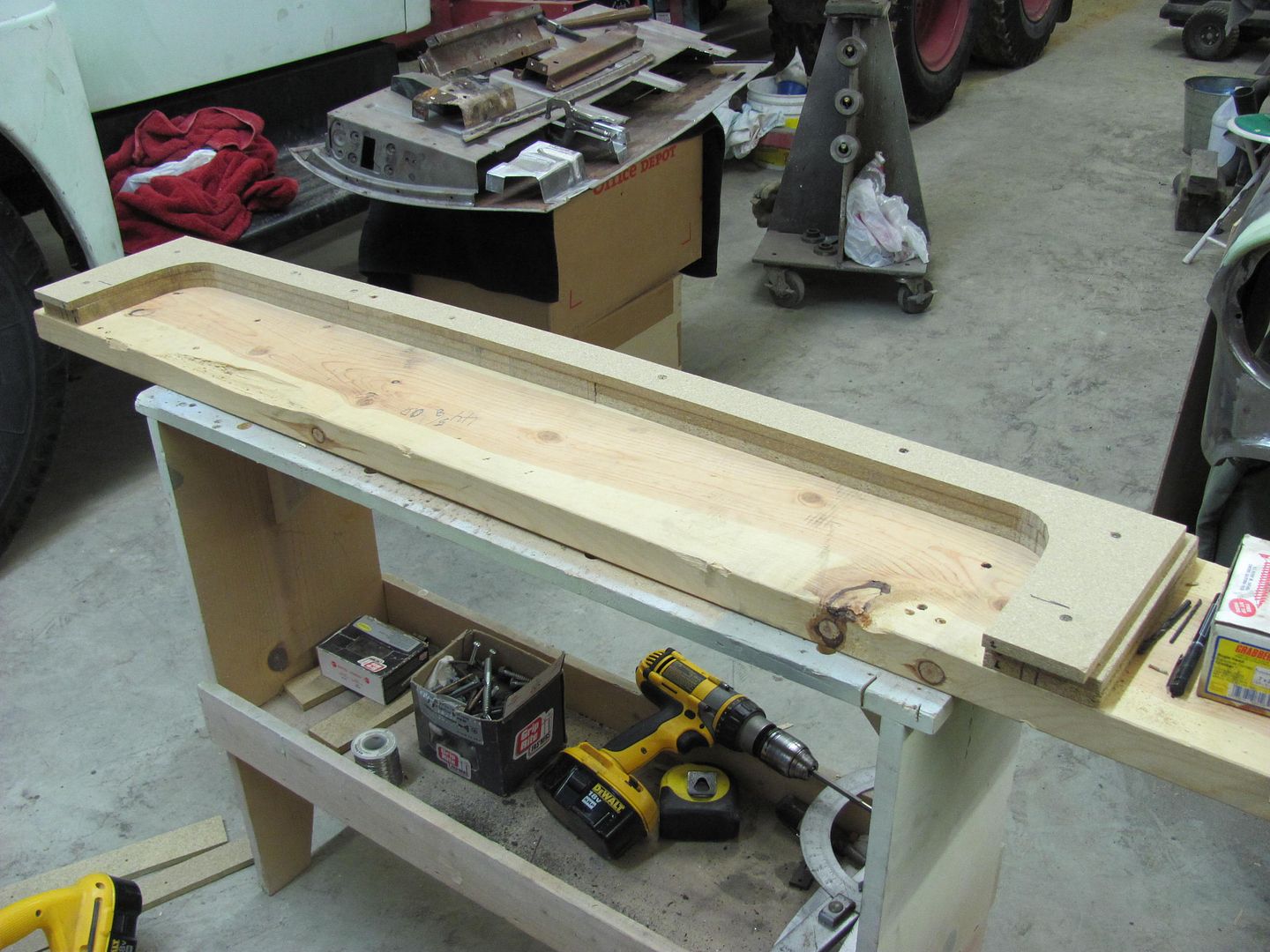
Here's the continuing saga....

The second bend in shows a bit of a taper, from about 1/8" height thickness at the side, to about 1/4" on the corners, to about 1/2" in the center of the gate.


Picture649.jpg


Picture650.jpg


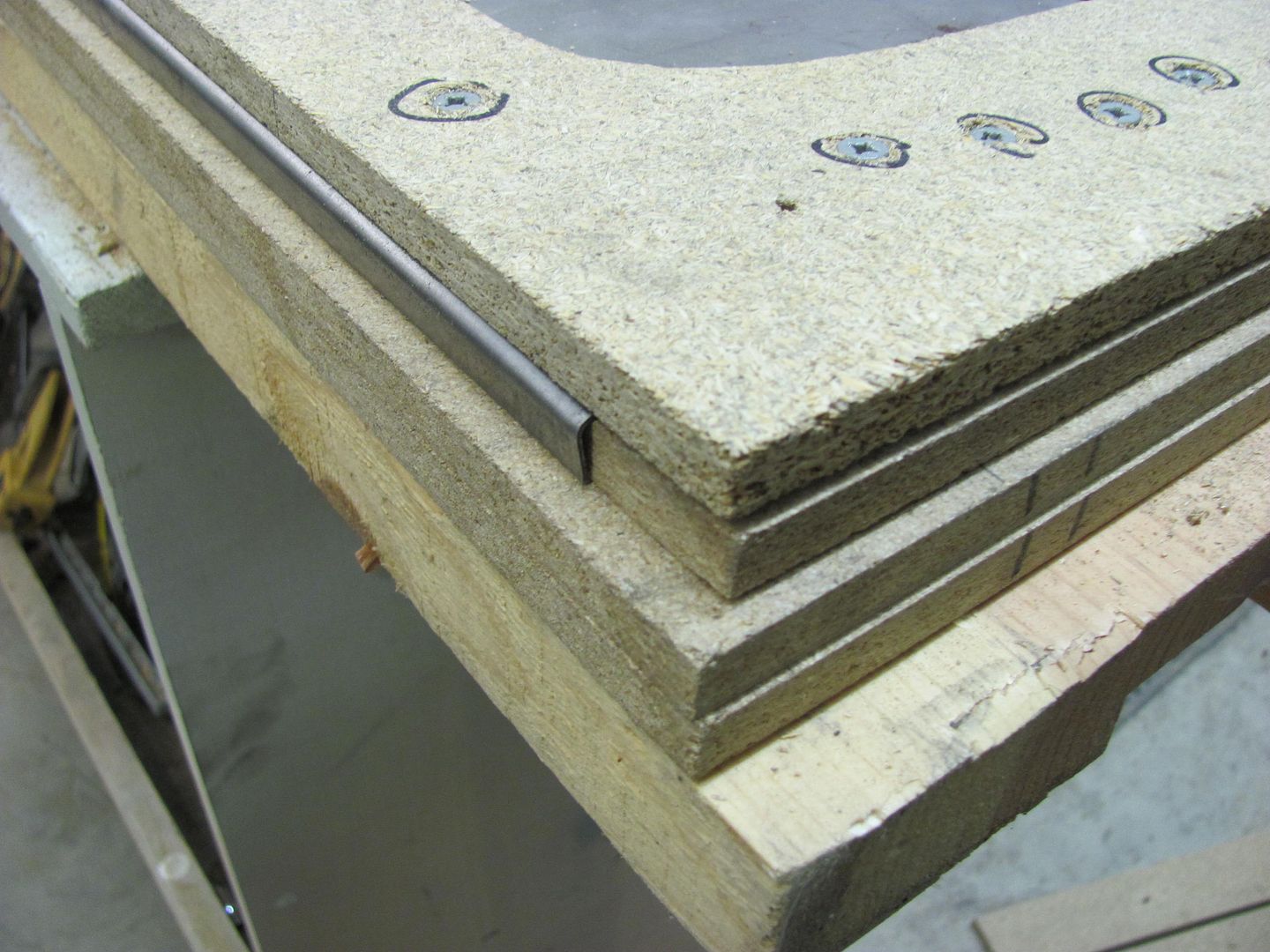
This will require the next set of MDF to taper off on the ends....


Picture652.jpg


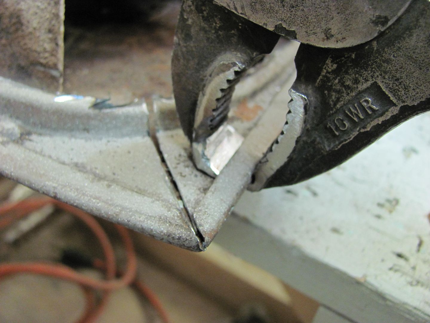
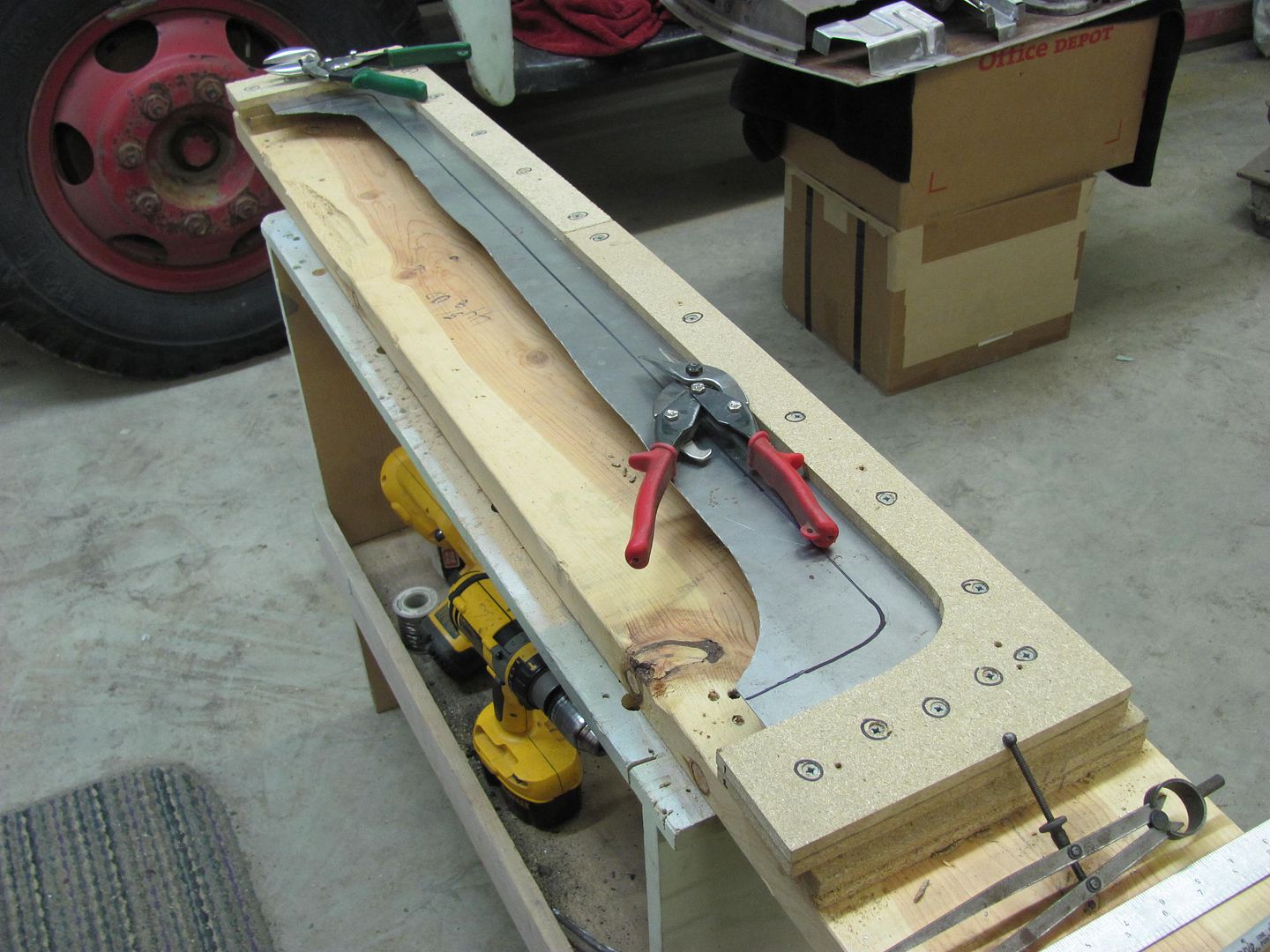
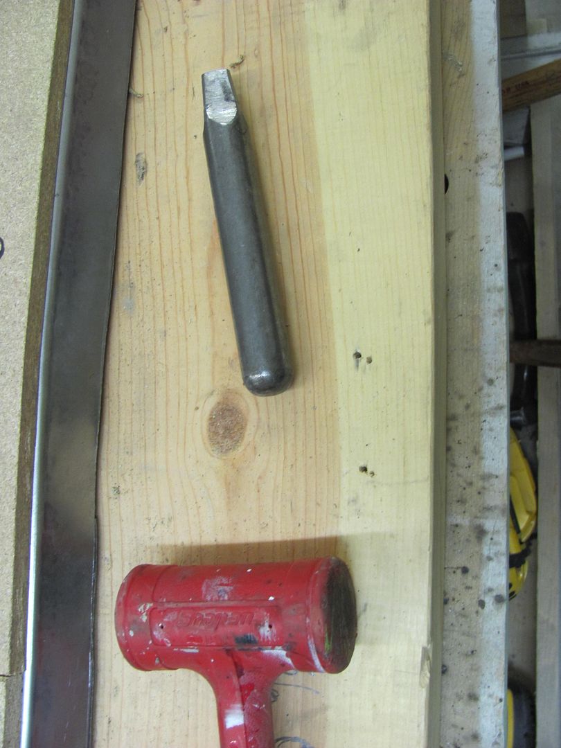
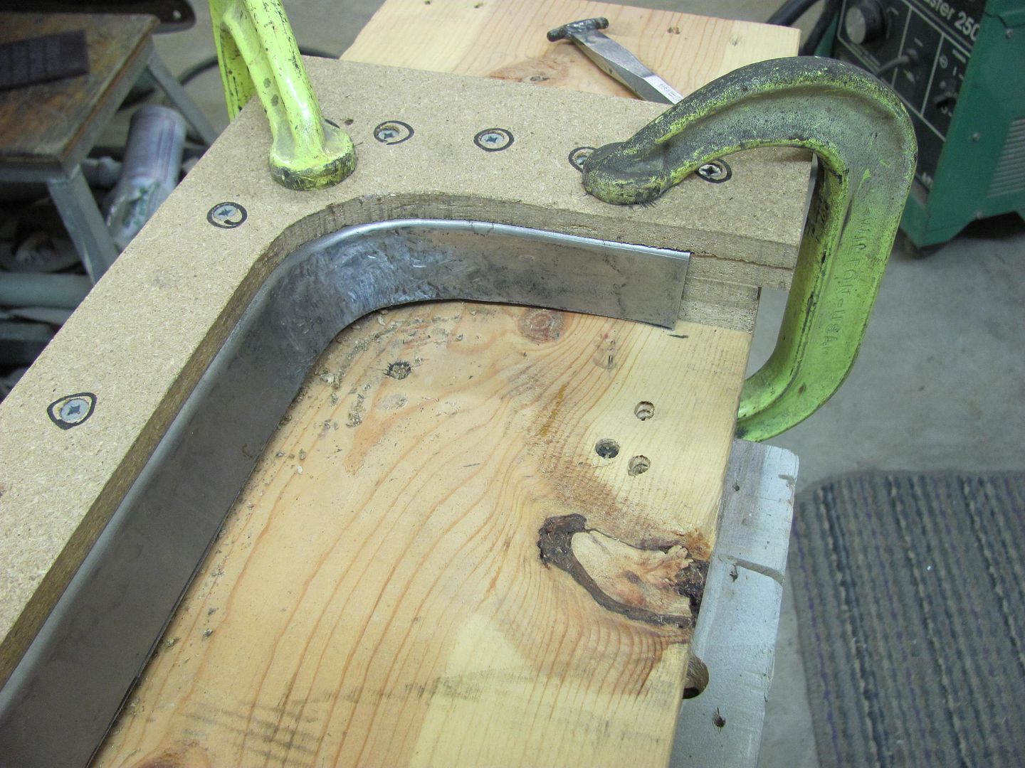
....and folded over as before. Because there is another reverse bend in about another 1/4", there was no need to completely shrink the corners flat. Just enough to provide that bend, and also shown is todays tool of choice for working the corners for this exercise.


Picture657.jpg


Picture658.jpg


Picture659.jpg


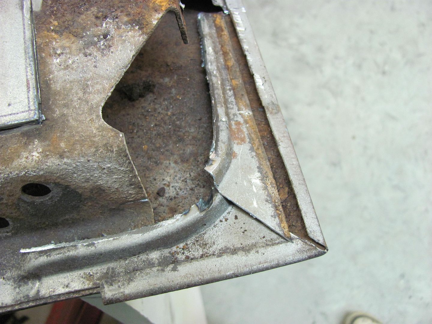
And if you'll notice the lower section is now in two pieces, that comes from measuring incorrectly (wrong bend). About a 3/8 wide strip will be bent, added afterward and welded in place.


Picture661.jpg


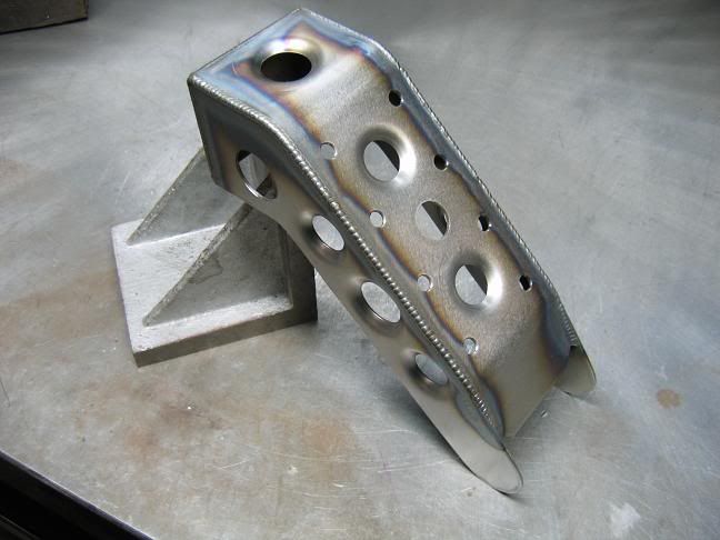
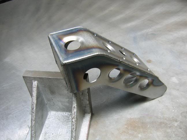
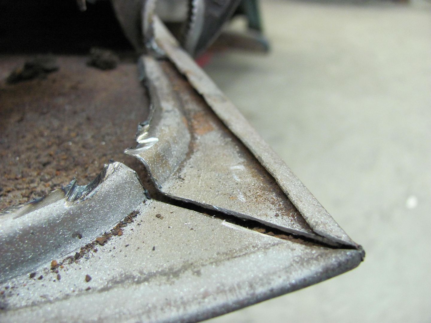
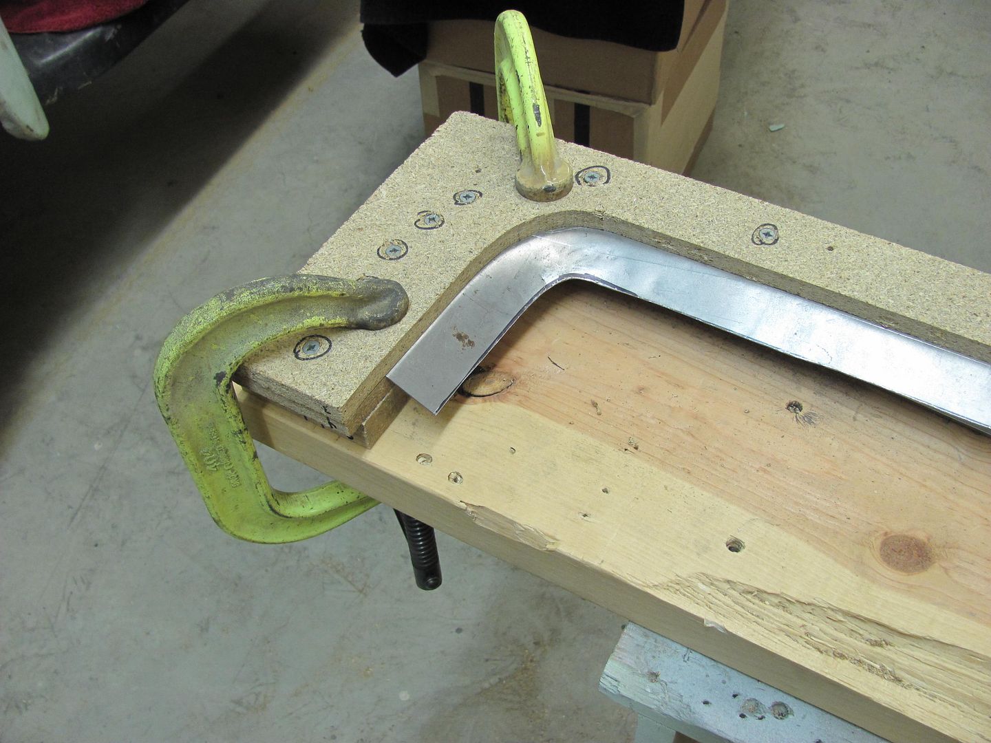
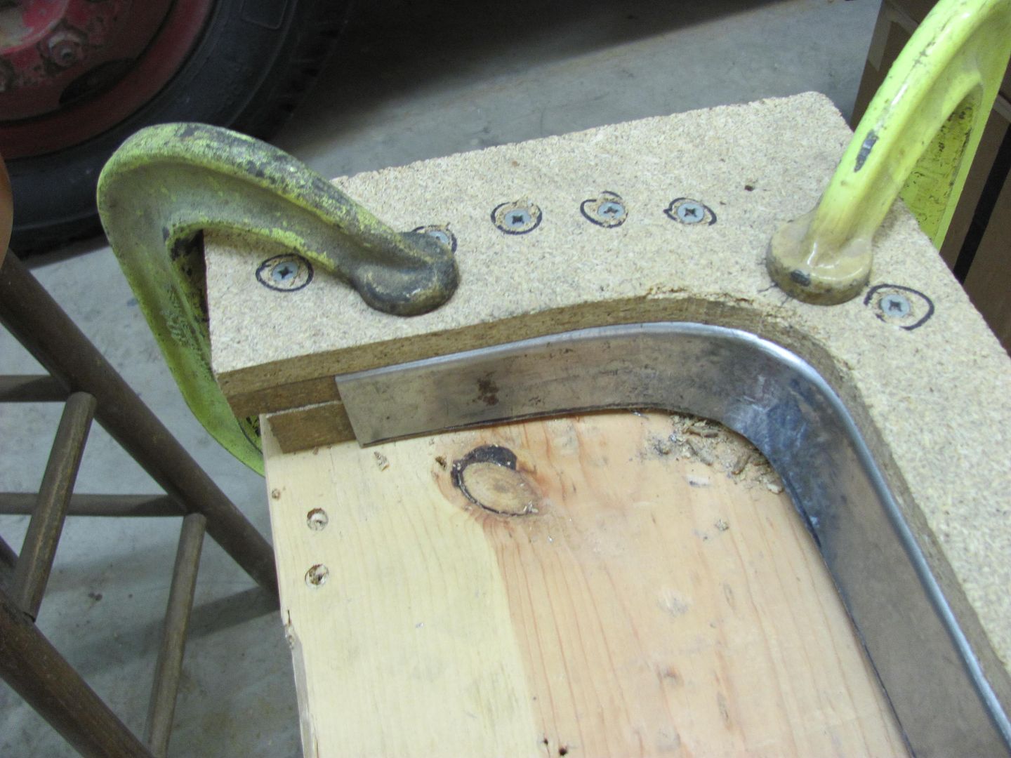
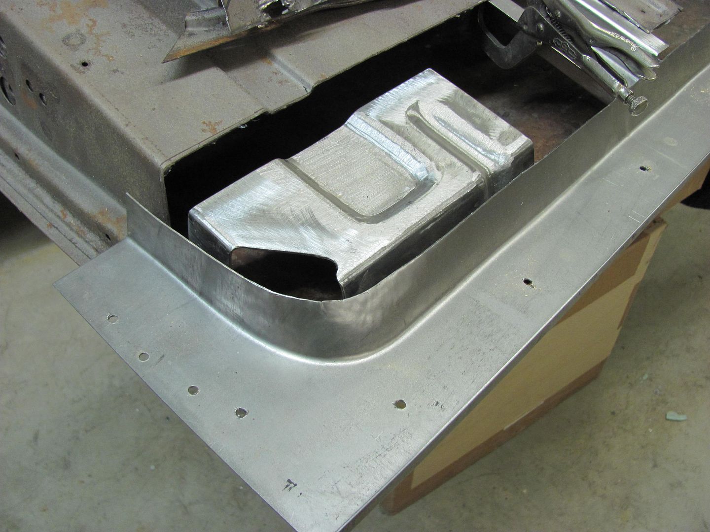
And the reverse bend after forming....


Picture663.jpg


Picture665.jpg


Picture664.jpg


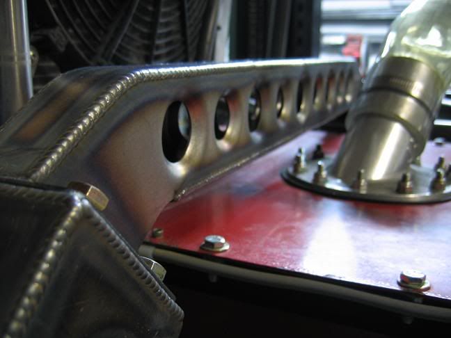
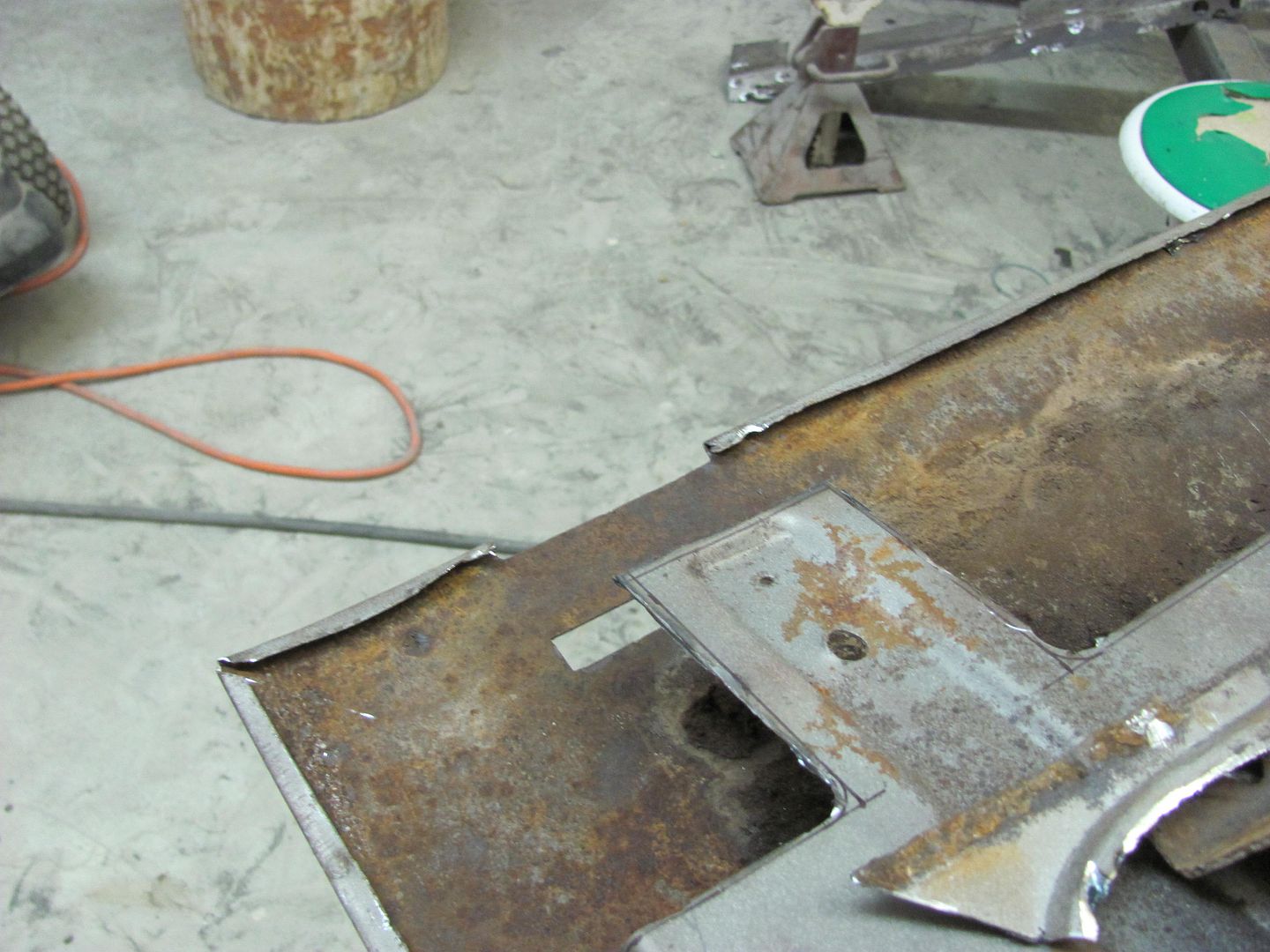
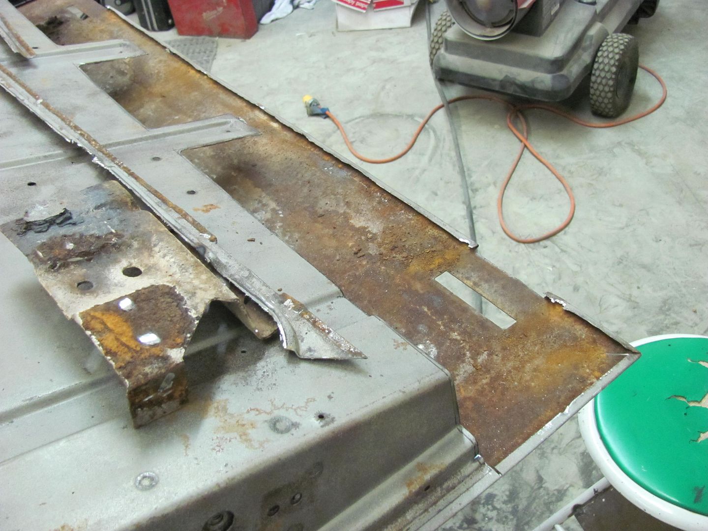
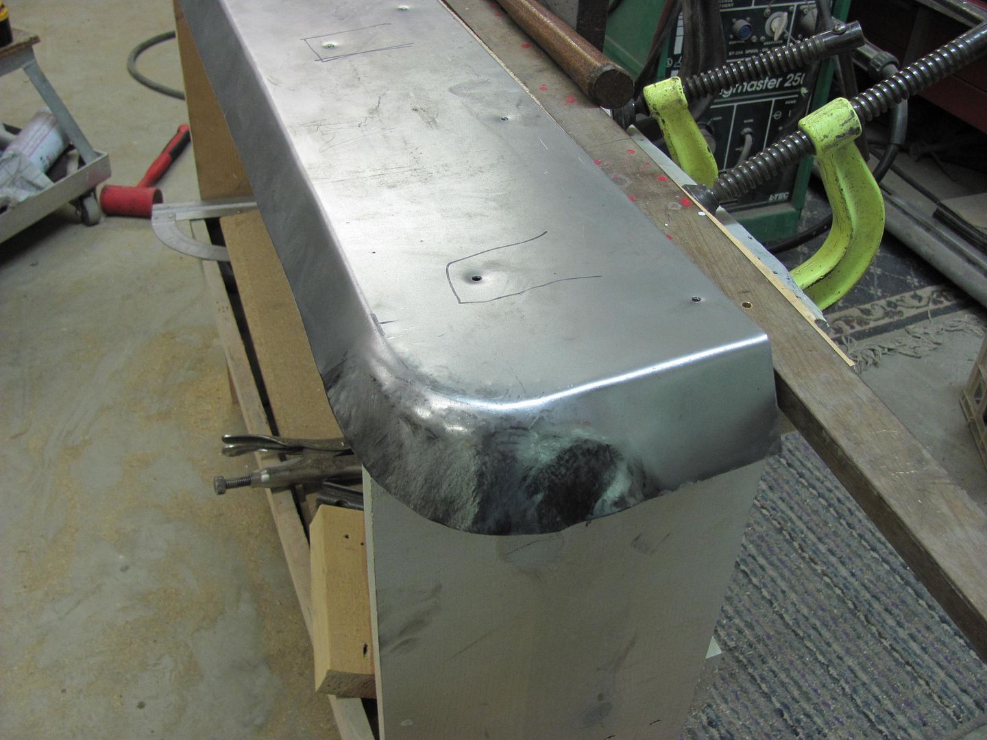
Comparison to the original. Needs a bit of clean up work, but should work fine.


Picture667.jpg


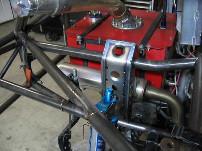
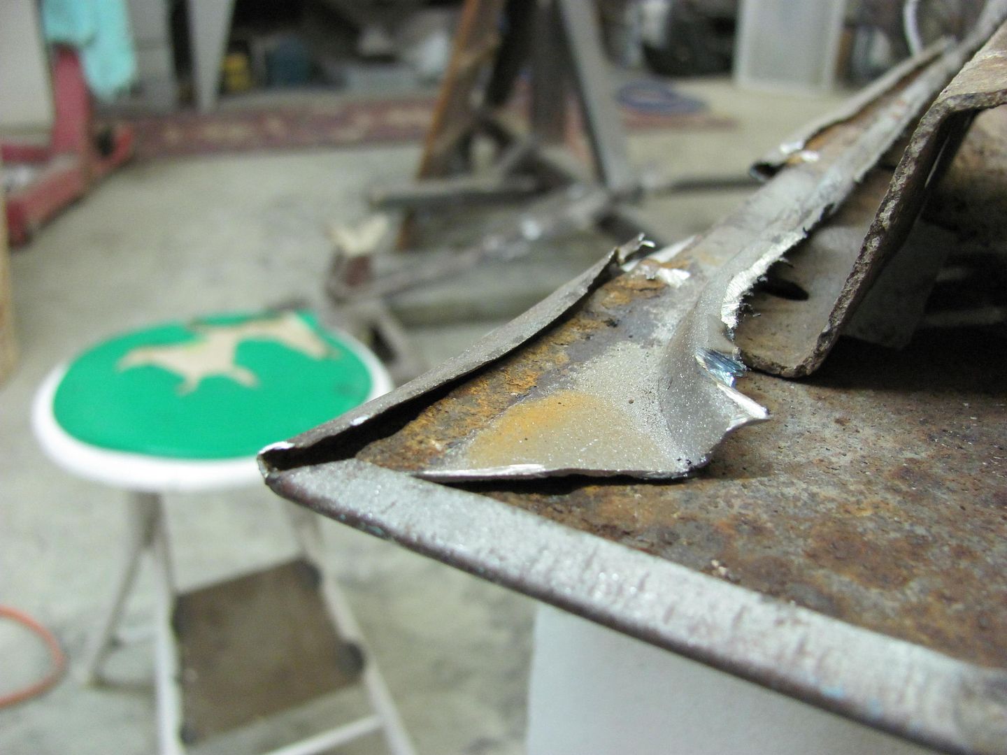
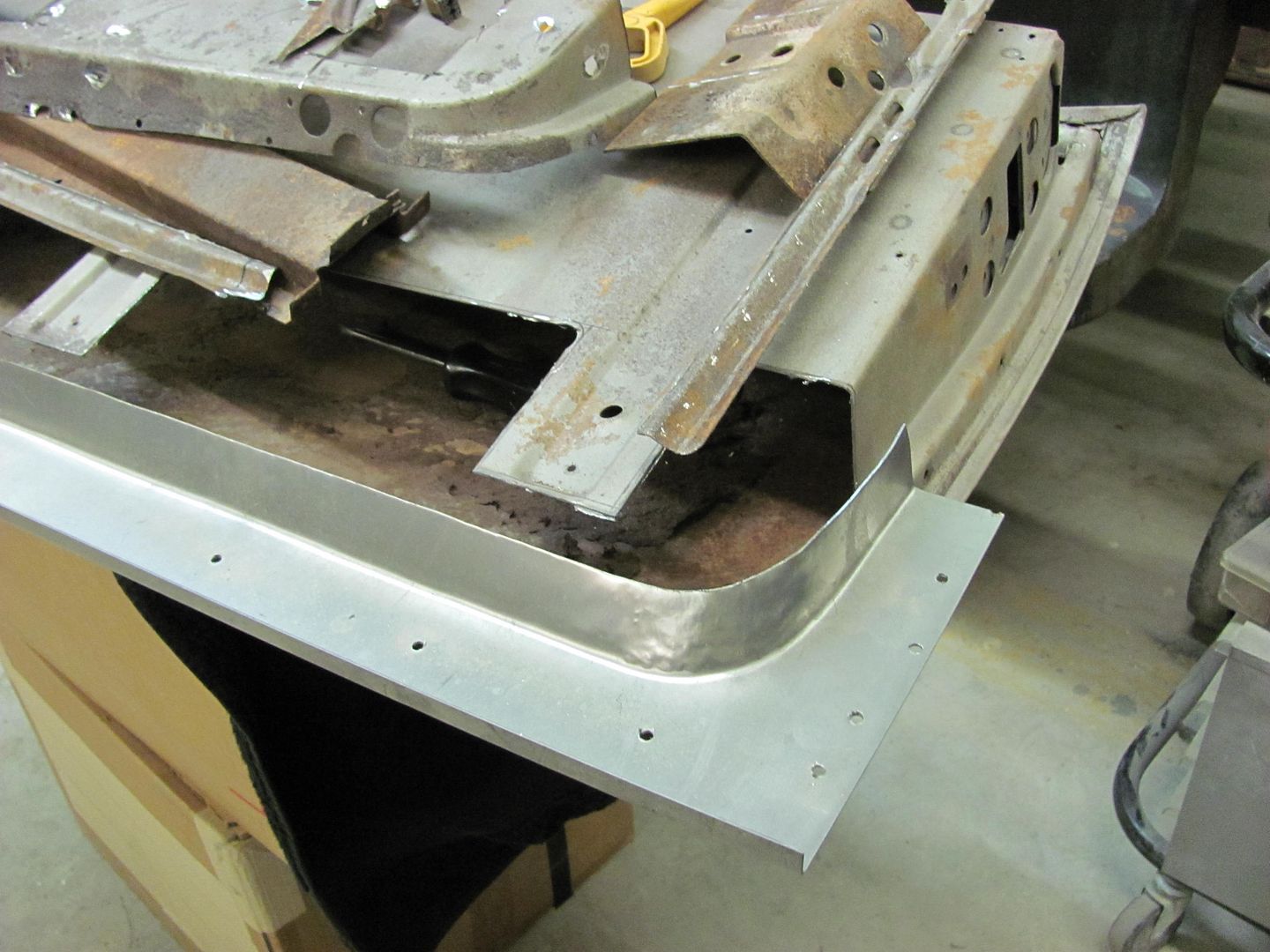
And then the repair parts (the ones made so far...) trimmed and fit up for a better look..


Picture669.jpg


Picture670.jpg


Picture672.jpg


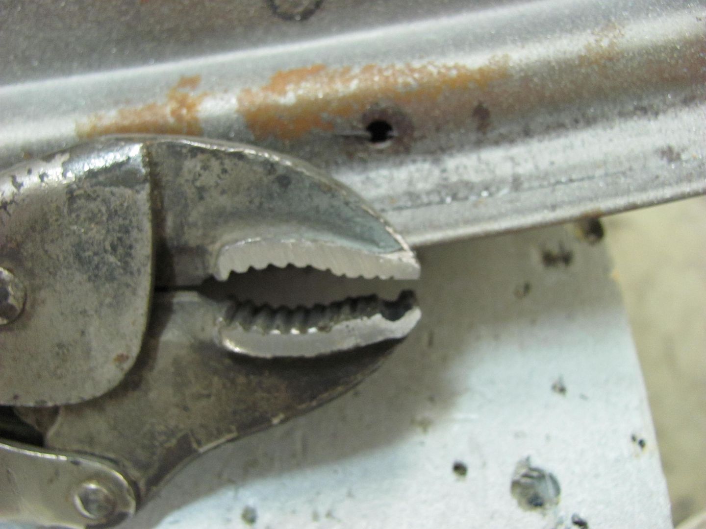
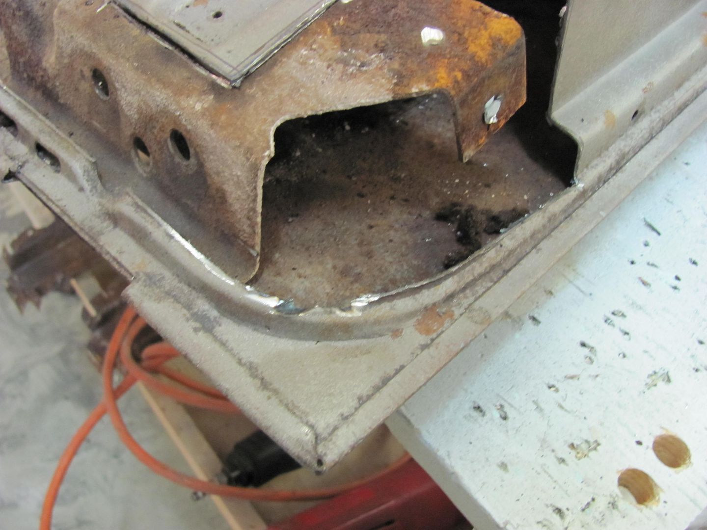
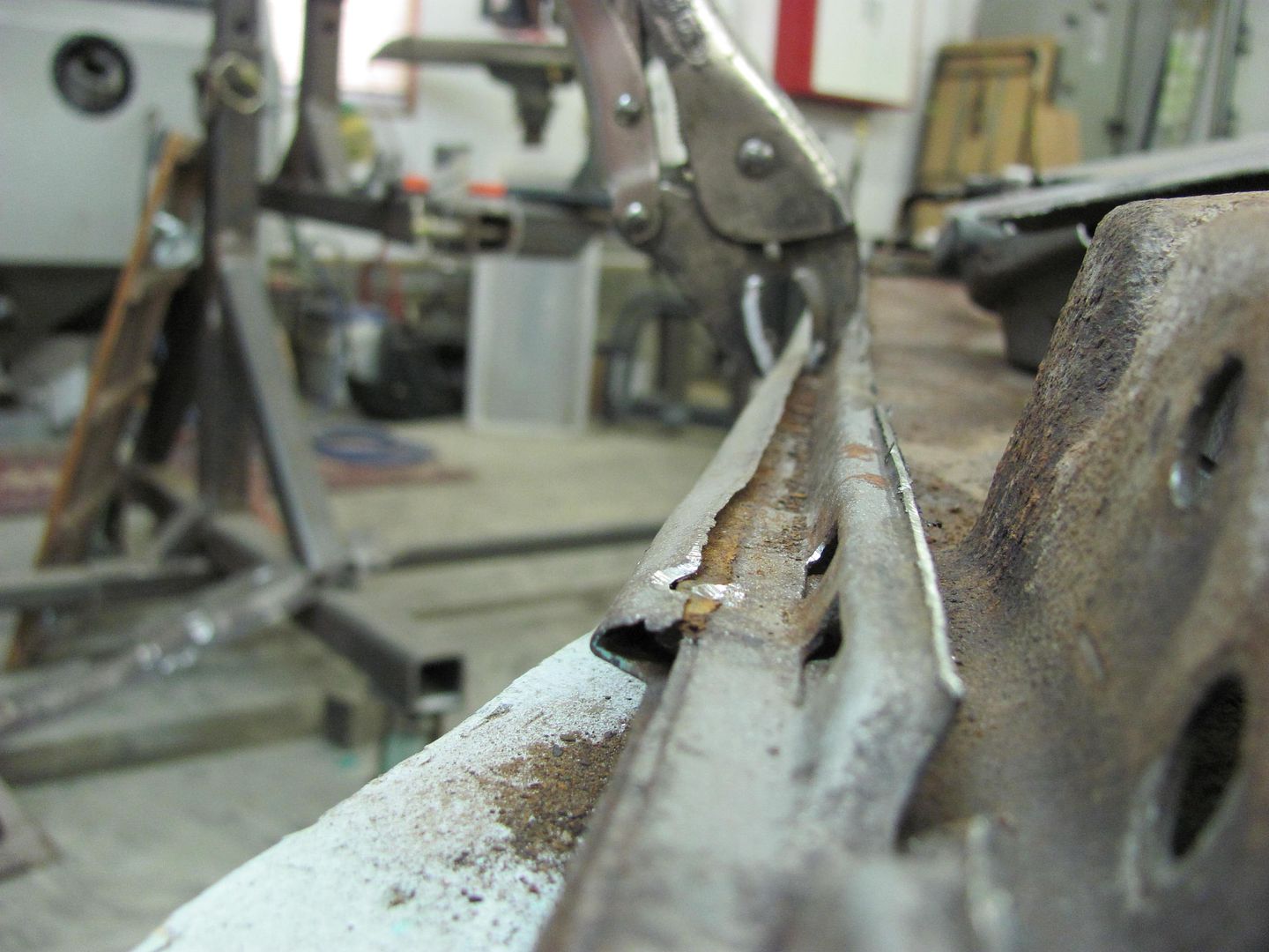
Moving on to the stiffening bead in the tailgate, most were still intact but one did have rust issues, just like the surrounding metal.


Picture674.jpg


Picture675.jpg


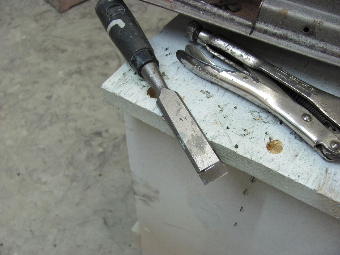
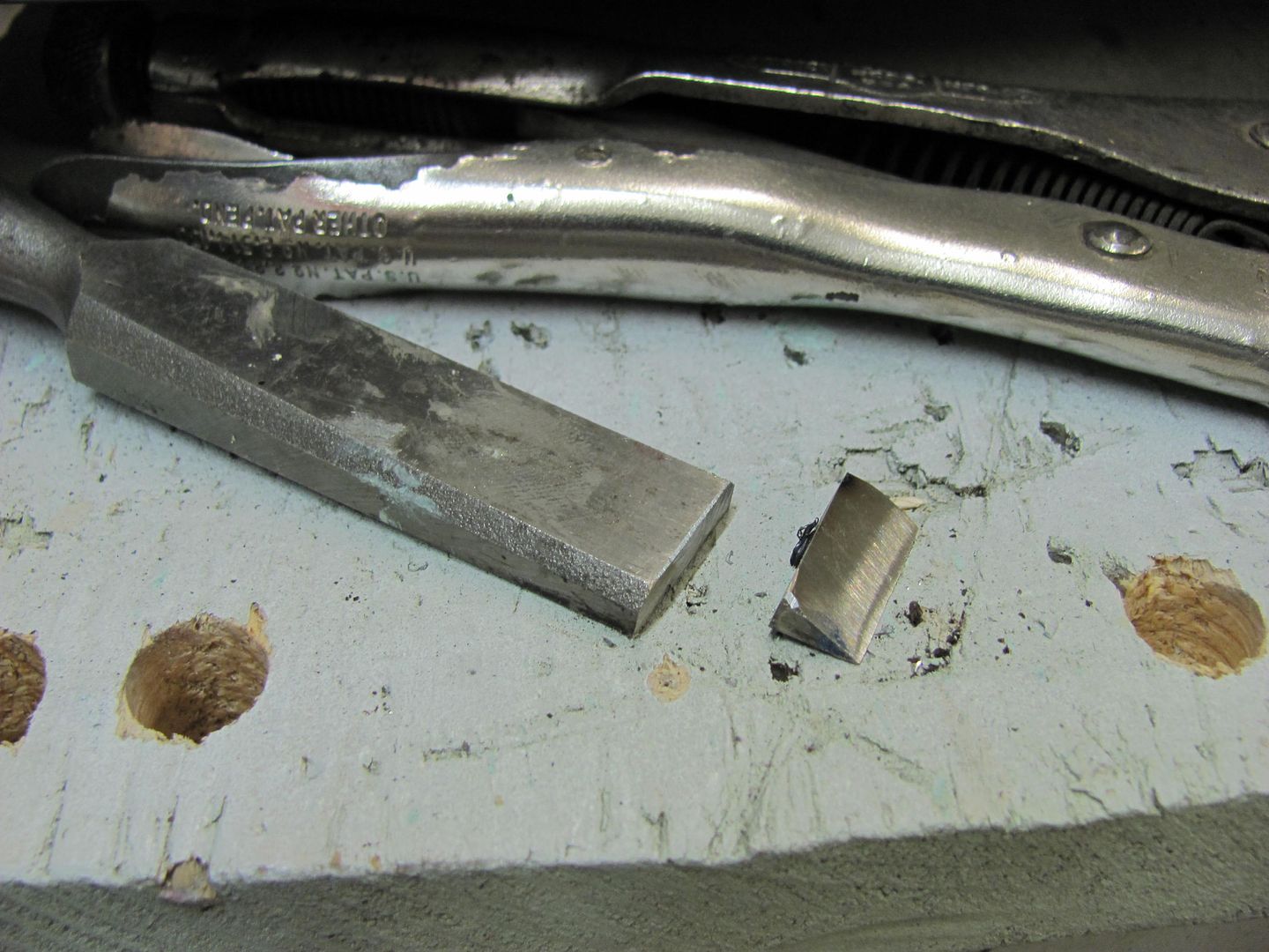
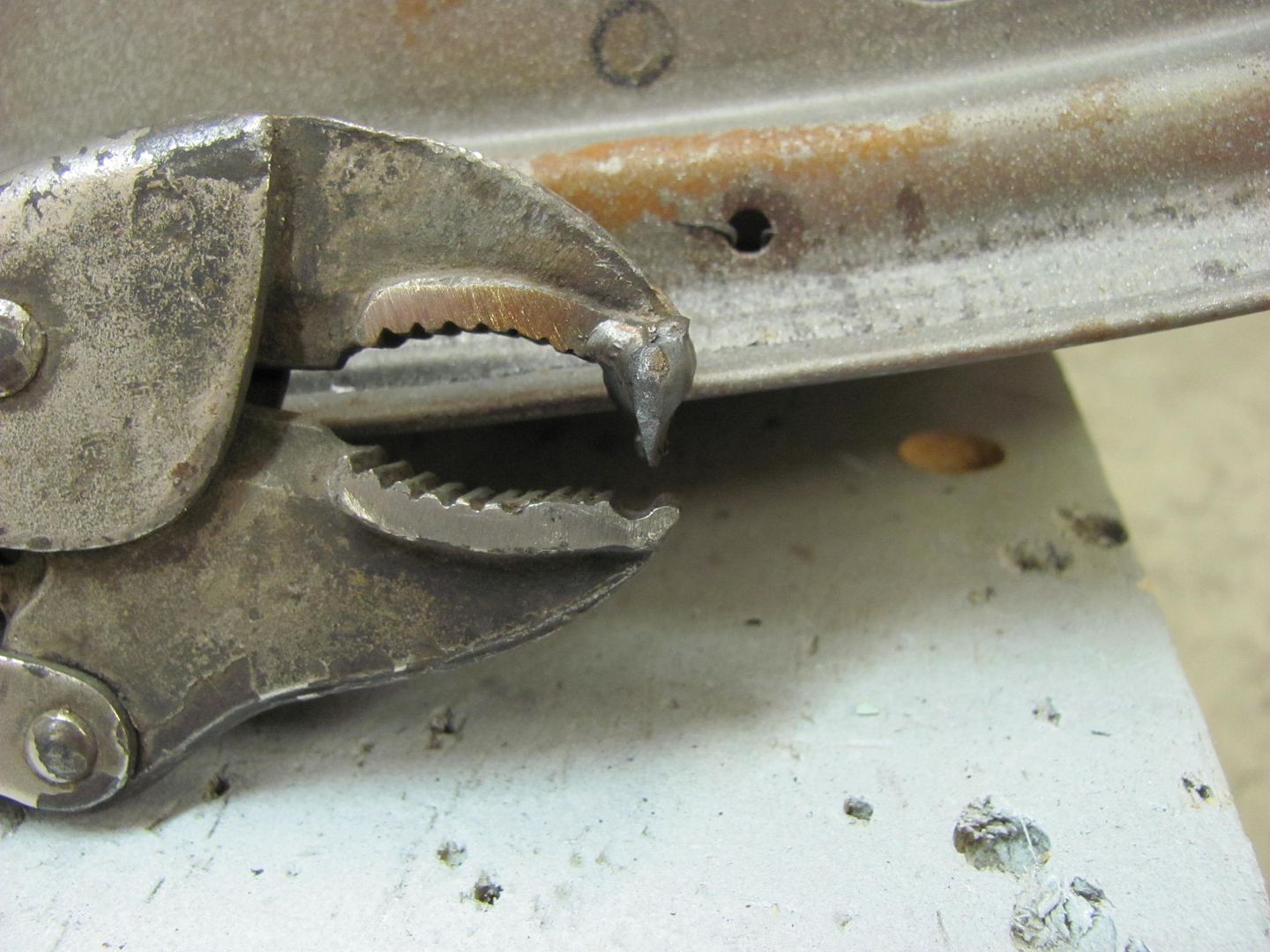
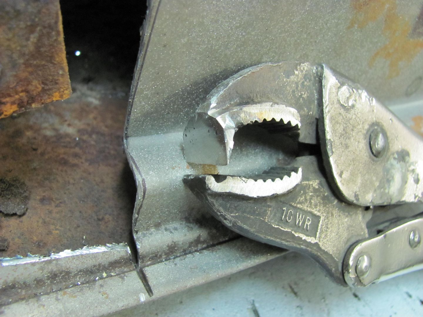
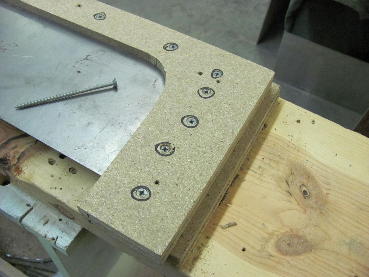
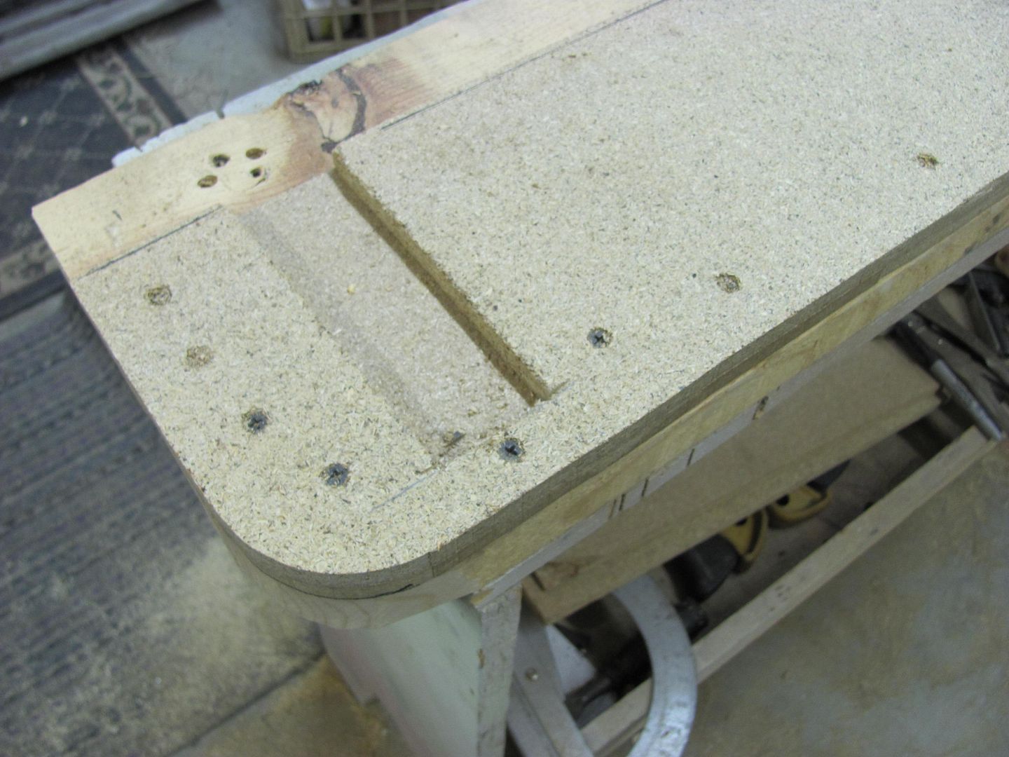
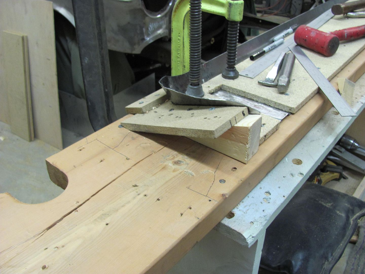
To make this detail, a suitable "punch" is made by welding some 1/8 thick plate to the end of a 1-1/4" square tube. For the "die", the nicks and welding slag was cleaned off the vice, and it was opened to the correct size.


Picture679.jpg


Picture681.jpg


Picture682.jpg


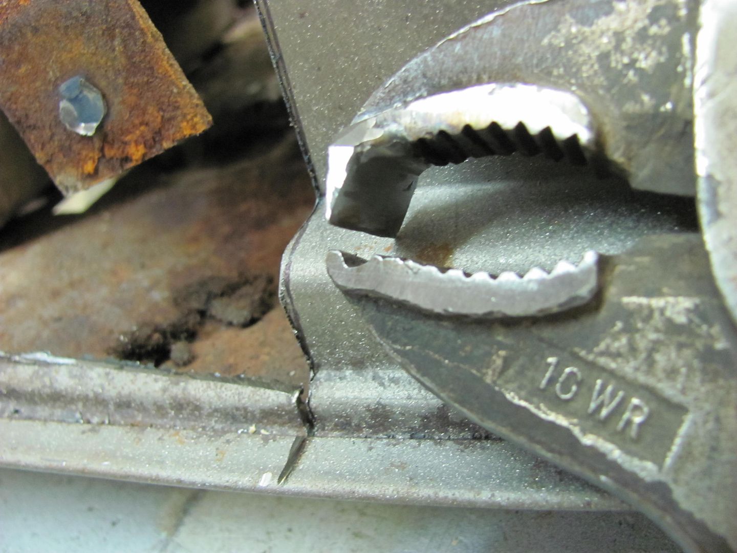
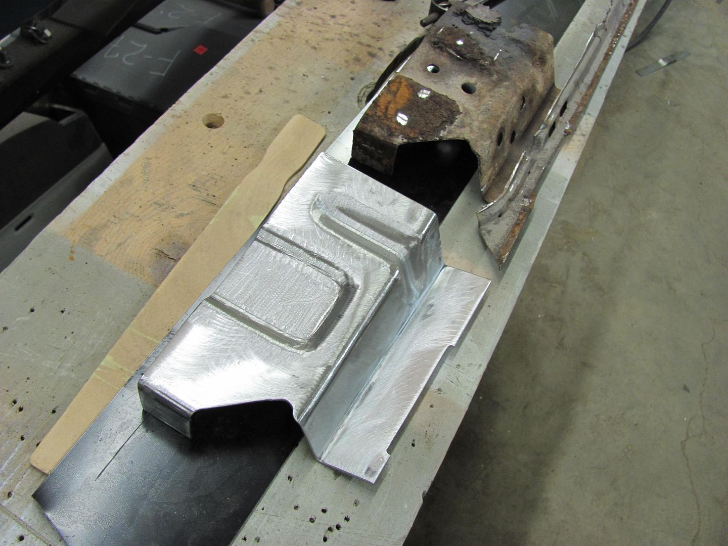
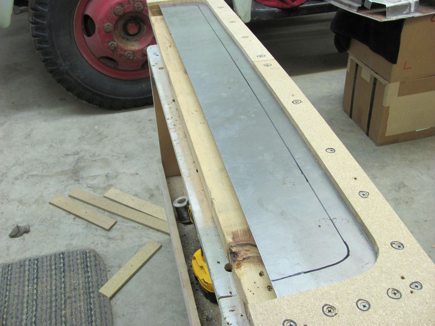
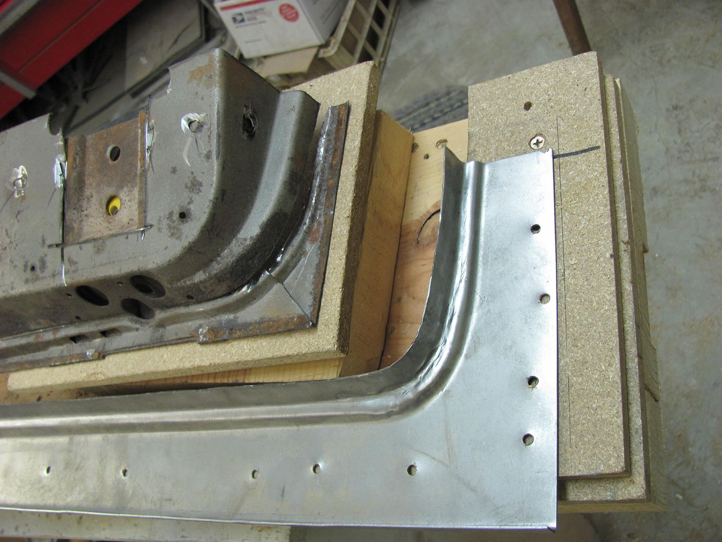
The next repair patch is centered over the tailgate and the approximate position of the stiffener bead is marked. The area is prestretched in the wheeling machine.


Picture676.jpg


Picture677.jpg


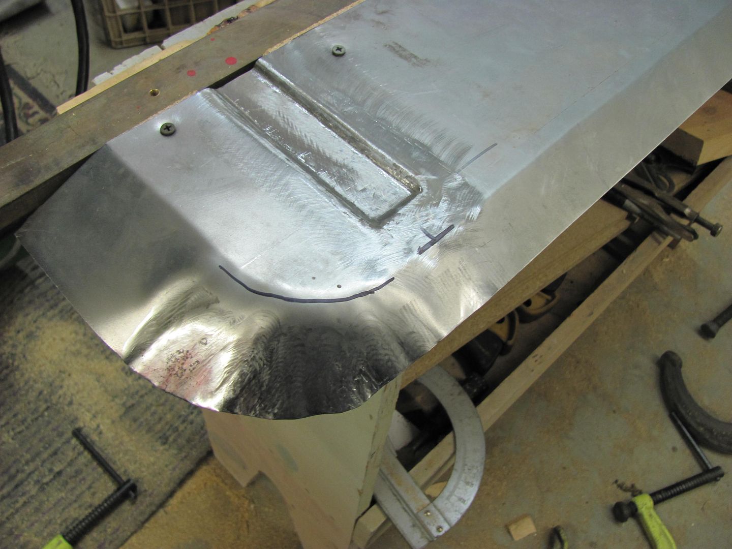
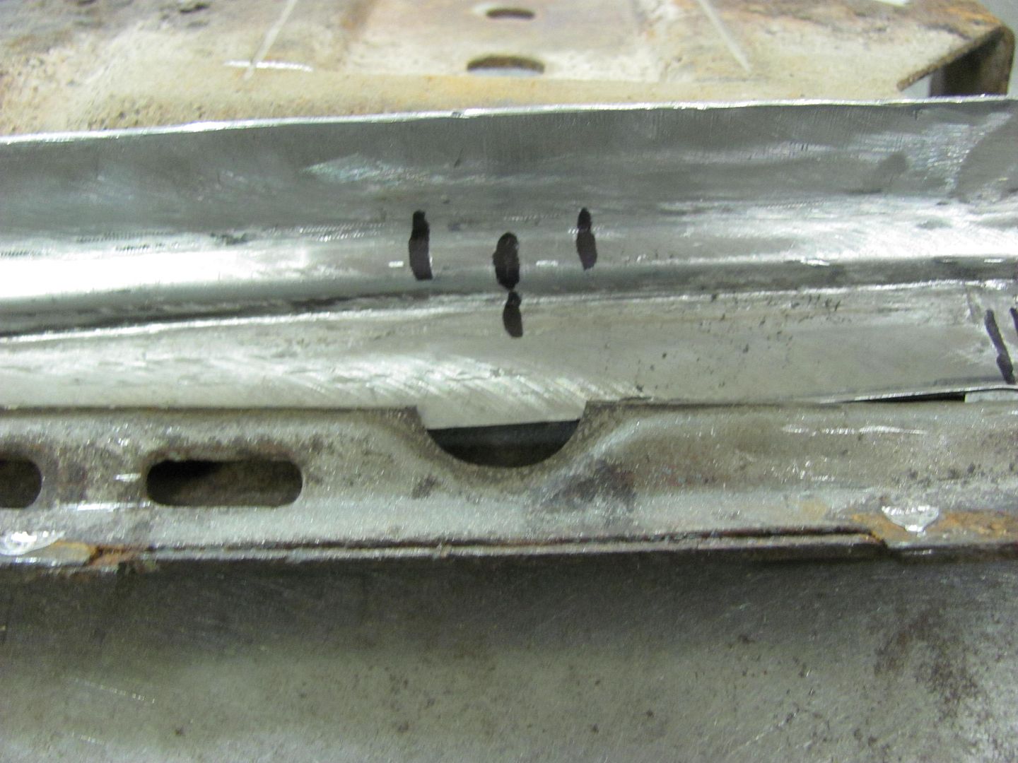
After some forming with my high tech punch and die, and some fine tuning afterward, the roughly finished product and a test fit against the tailgate...


Picture683.jpg


Picture678.jpg
 
Last edited:

rickairmedic

Well-known member
Joined
May 31, 2005
Messages
4,165
Location
louisville ,Ky
Robert I always enjoy your posts . I am planning to start on my 1962 F100 unibody this year and have been watching your posts closely to try at the least to learn something as I will have plenty of rust repair to deal with on this truck .


Rick
 

MP&C

Well-known member
Joined
Oct 21, 2009
Messages
4,396
Location
Leonardtown, MD
Here's the hammer form for the final piece of the puzzle. A notch is cut out for the stiffener bead to lay in...


Picture685.jpg


Picture684.jpg


I had a nice heavy brass flat bar, so it was put to use with the c-clamps, and the intial bends are formed to mark where the corners will be......


Picture687.jpg


Picture688.jpg


Then the points are trimmed off the corners and over we go to the Lennox with the Thumbnail shrinking die. Tonight I had a nine year old photographer helping for a bit...


Picture690.jpg


The initial shrinking....


Picture691.jpg


Picture692.jpg


One thing I had to keep in mind, the dies need to be loosened up as you go, as the corners shrink and the metal thickness increases. Here's where I stopped for dinner... A bit more and we should be ready to tip the reverse bend..


Picture697.jpg


Picture698.jpg


And here's the rest of this evening's work, starting with the hammerform for the corner reverse bend detail..


Picture001.jpg


Picture002.jpg


After quite a bit of hammering....


Picture004.jpg


...and a trial fit to the tailgate


Picture005.jpg
 
Last edited:

MP&C

Well-known member
Joined
Oct 21, 2009
Messages
4,396
Location
Leonardtown, MD
This evening took time to back up a bit, and fine tune the flange parts. The originals had an offset relief for the hinge bolting plate so it could sandwich between the inner and outer skin.


Picture007.jpg


Picture008.jpg


...and after a bit of hammer work, here is the result....


Picture009.jpg


Next, to form the relief around the center bolt hole. The hole is marked, and a negative formed in a piece of MDF with a 3/4" drum sander.....


Picture010.jpg


Picture011.jpg


Picture012.jpg


After using various punches with newly rounded tips, and a 3/4" dia piece of round stock as an anvil......


Picture013.jpg


And the next bend is formed...


Picture014.jpg


Picture015.jpg


....and starting on the next side..


Picture016.jpg
 

A_Pmech

Well-known member
Joined
May 8, 2007
Messages
8,002
Location
IL
This is a great thread, please keep posting guys!

I've learned a lot about sheet metal work looking at your photos and descriptions.

:thumbup:
 
To avoid these ads, REGISTER NOW!
Top Bottom