To avoid these ads, REGISTER NOW!

Show us your VFD conversions/installations

pcmeiners

Well-known member
Joined
Aug 13, 2009
Messages
7,825
Location
In the only town in Pennsylvania, Bloomsburg.
No pictures, but on my mobile setup I used line reactors on the input and outputs of the VFD. The only issue is the cost of the reactors, and the weight as my box must weight 30 lbs; as mention Ebay is the way to go. Since I am using the VFD on multiple different motor, none rated for VFD use, I figured the reactors can only help as to higher voltage/insulation issue and noise.
 
Last edited:
To avoid these ads, REGISTER NOW!

fusillade

New member
Joined
May 4, 2011
Messages
2
I used to deal with VFD's quite often in my previous life as an engineer. Whenever we spec'd a machine with a VFD we were also careful to spec a "VFD rated motor". Basically it was a 3 phase motor with a 110 percent service factor. It looks like most of the applications here are ignoring this? Is anyone having reliability issues with motors overheating? Probably for short usage it may not be an issue. Also, many of the older motor son some of this style of equipment were really overbuilt and can sustain the heat.

Here is a good explanation of what I am referring to:
http://motors.automationdirect.com/Information/compare.html

Also,as noted by the issue with GFCI problems, these things can throw a ton of noise on the AC lines in operation. In an industrial setting this is not too much of an issue. In a home setting beware of future problems with power supplies in TV's and computers and especially with home automation devices that communicate over the AC lines such as Insteon of X10. This may vary greatly with the manufacturer of the drive. Again, these things were designed for an industrial environment.


Sent from using Tapatalk

I'm VFD tech and you basically hit the nail on the head. I'd just like to add the following:

Generally speaking, the cheaper the motor - the more you'll have pay attention to the specs. I'd say say a service factor of 1.1 (or, it can run at 110% of what its rated at) is low, but the stuff I typically work on is higher end and more critical. Please people, understand that when you see 110% that you can easily equate that to the max RPM of your engine. That's not what you're going to be running it at, or at least not for long.

If you have a new set up, it's easier sometimes to figure out what motor suits the application best and work backwards - or at least its easier for me to match a drive to a motor than the other way around sometimes.

Your drive should be "bigger" than your motor. I can't tell you how many times I go on a call and people are having issues because they spec'ed the motor and drive too tight and don't have any "wiggle room". There are going to be times when you're going to pull more power to the motor - that's fine, the service factors are there for start ups and random spikes in torque - but it'll heat up and overwork your drive. The drive is going to start shutting down on you and have all sorts of random problems, but they all originate from over stressing the drive. Spec your drive out a little larger than the motor and you'll see better results and it'll create less heat.

I see a lot of guys here mounting drives next to the motor. It's not wrong, but its not what I would do. I'd set my drive back a little, away from the machine. Trust me, if everything's in your shop it'll be ok. Run a cable over for your motor and the switches - typically speed is controlled on a analog input to the drive that will either be 4-20 mA or 0-10 VDC. Set it to 0-10 volts and get a potentiometer (pot) with a fancy knob to mount on your machine. When you get a pot, remember the more turns it has means the finer control you have. Less turns means it'll be more course. You shouldn't have to be opening up a panel to adjust your speed, it just seems wrong to me.

I think it's great that guys are doing this. Don't be intimidated, there's so much info and people out there that will help, and once you gain that level of efficiency and control you won't be able to go back. It'll be like going back to dial up internet after getting on a real high speed connection.
 

PETE14

Well-known member
Joined
Jun 13, 2010
Messages
524
Location
Denver, CO USA
I just found this thread. Pretty interesting. I don't have anything on VFD - at least not yet.

For all of the Tubalcain (MrPete222) fans out there (on Youtube), he did a several part series a couple of years ago. He was a rank beginner, so the videos are showing how he set up his first attempt. They are worth watching, if you like his videos. I did a quick search, and it looks like they are "Machine Shop Tips" # 138 thru 142, and also 149.

He did some things well, and others not so well, but like I said, it was his first attempt starting from scratch. At the least, he shows what they are, what features his has, and how they work. This is the first video in the series:

 
OP
T

Techie1961

Well-known member
Joined
Feb 18, 2014
Messages
1,520
Location
Pickering Ontario Canada
I made up a panel and support plate for the VFD that I'm installing on the drill press. It took me quite a lot of pondering to figure out how I would do this one due to the shape of the VFD and that I would have preferred it vertical. I wanted easy access to the controls as well as cover up the existing hole that was used for the switches (power and light) and clear other parts on the main body of the machine.
25224177091_58363c3b21_c.jpg


I'm planning to have a label made for the front of the enclosure. The upper row is for the light and main power while the lower row is the speed pot and to select drill on, off, and tapping mode with a foot switch. I used a light duty pot for now but hope to find one that is the same as the switches.
25291016456_456624d581_c.jpg


I modified the lamp mount so that it would hold a LED bulb. It's very bright and draws very little power. I'm going to form up some of the brushed stainless steel that I have to close it off.
24949519709_a36d17b178_c.jpg
 

RonRock

Well-known member
Joined
Oct 6, 2007
Messages
1,171
Location
Iowa, USA
So how big of a 3 phase motor can be run with a VFD?

I looked at one companies listing and the largest single to three phase was 3 HP. Not sure if that is as large as they go.

I hate to think of all the 3 phase motors I've scrapped. And equipment I have passed up because of 3 phase. The things are like magic.
 

beakie

Well-known member
Joined
Feb 21, 2014
Messages
492
Location
Ontario, Canada
So how big of a 3 phase motor can be run with a VFD?

I looked at one companies listing and the largest single to three phase was 3 HP. Not sure if that is as large as they go.

I hate to think of all the 3 phase motors I've scrapped. And equipment I have passed up because of 3 phase. The things are like magic.

you can power whatever size motor you can find a VFD for.
I just wired up a 5hp motor on my Delta/Rockwell 12/14" table saw.

I sourced my VFD from ebay, and see no reason to spend extra $$ on big names. Factorymotion is another good source.
 

manwithtools

ALLIANCE MEMBER
Joined
Aug 24, 2015
Messages
13,639
Location
Lebanon, TN
Single phase "input" operation on "a three phase input drive" requires a de-rating factor of about 1.73 (square root of 3) because the input current requirement goes up by not providing 3 phase power. If you are trying to operate a 5 hp motor and have single phase power, a 7.5 hp VFD drive would work marginally (1.5 times), a 10 hp VFD drive (2 times) would be preferred.

The above assumes a three phase input drive. Ones specifically designed for single phase input typically top out around 3 hp.
 
Last edited:

manwithtools

ALLIANCE MEMBER
Joined
Aug 24, 2015
Messages
13,639
Location
Lebanon, TN
I made up a panel and support plate for the VFD that I'm installing on the drill press. It took me quite a lot of pondering to figure out how I would do this one due to the shape of the VFD and that I would have preferred it vertical. I wanted easy access to the controls as well as cover up the existing hole that was used for the switches (power and light) and clear other parts on the main body of the machine.

You are probably alright mounting the unit horizontally for infrequent use, but they are designed to be mounted vertically for proper heat dissipation. Check out the manual for the following:

"Orientation: Install the drive vertically to maintain maximum cooling effects."

If a VFD as a heat sink, you will notice the ribs are oriented vertically to create a "chimney" effect for conductive cooling. It's best to orient the drive accordingly, also they should be securely mounted to a steel panel as they rely on that mass to aid in cooling. This is more important when you have more than one drive in an enclosure, caloric calculations are required to determine enclosure size and the possible need for supplementary cooling (fans, AC units, etc.). This is more important in an industrial setting than home use, but it's best to read the manual and apply the drive as designed.

Here's another blurb from your drives manual "Drive reliability improves in environments without wide temperature fluctuations. When using in an enclosed panel, install a cooling fan or air conditioner in the area to ensure
that the air temperature inside the enclosure does not exceed the specified levels."
 
OP
T

Techie1961

Well-known member
Joined
Feb 18, 2014
Messages
1,520
Location
Pickering Ontario Canada
You are probably alright mounting the unit horizontally for infrequent use, but they are designed to be mounted vertically for proper heat dissipation. Check out the manual for the following:

"Orientation: Install the drive vertically to maintain maximum cooling effects."

If a VFD as a heat sink, you will notice the ribs are oriented vertically to create a "chimney" effect for conductive cooling. It's best to orient the drive accordingly, also they should be securely mounted to a steel panel as they rely on that mass to aid in cooling. This is more important when you have more than one drive in an enclosure, caloric calculations are required to determine enclosure size and the possible need for supplementary cooling (fans, AC units, etc.). This is more important in an industrial setting than home use, but it's best to read the manual and apply the drive as designed.

Here's another blurb from your drives manual "Drive reliability improves in environments without wide temperature fluctuations. When using in an enclosed panel, install a cooling fan or air conditioner in the area to ensure
that the air temperature inside the enclosure does not exceed the specified levels."

Thanks! You're experience with these is very valuable to the rest of us and it's appreciated. The back plate that I mounted it to is a nice chunk of aluminum so I'm hoping that helps it as well. I left the back of the cover open and there's a hole just ahead of the drive into the frame casting. Hopefully the fan from the drill press motor will create enough turbulence to keep the air moving.

If it overheats, is there a warning? Does it start to overload or just fail? I suppose I could add a small fan at the back.
24727850694_96b7bb0d4b_c.jpg
 
OP
T

Techie1961

Well-known member
Joined
Feb 18, 2014
Messages
1,520
Location
Pickering Ontario Canada
Here's a question for the VFD experts in the class. There are parameters that define such things as mid point voltage, mid point frequency, etc. I'm hoping to understand these a bit better.

For example, I would have thought that the motor voltage would always be say, 220 V for a 220 motor and only the frequency would change. I have seen some reference to V/Hz and suspect that this is related. Care to enlighten us with some simple equations?
 

beakie

Well-known member
Joined
Feb 21, 2014
Messages
492
Location
Ontario, Canada
Single phase operation requires a de-rating factor of about 1.73 (square root of 3) because the input current requirement goes up by not providing 3 phase power. If you are trying to operate a 5 hp motor and have single phase power, a 7.5 hp VFD drive would work marginally (1.5 times), a 10 hp VFD drive (2 times) would be preferred.

The above assumes a three phase input drive. Ones specifically designed for single phase input typically top out around 3 hp.

3hp rated ones top out @ 3hp... and 5hp VFD's top out @ 5hp. 7.5hp @ 7.5hp and so on and so on...point being?

I could have ran my 5hp motor off of a 3hp capable VFD and made 3hp... but I wanted all 5hp available, so I bought a 5hp capable VFD.

Typically people only need 3hp (drills,mills,lathes,saws,etc don't often need more than 3hp), so the majority of consumer grade VFD's are 3hp... but one can easily find higher rated units... typically.
 
OP
T

Techie1961

Well-known member
Joined
Feb 18, 2014
Messages
1,520
Location
Pickering Ontario Canada
3hp rated ones top out @ 3hp... and 5hp VFD's top out @ 5hp. 7.5hp @ 7.5hp and so on and so on...point being?

I could have ran my 5hp motor off of a 3hp capable VFD and made 3hp... but I wanted all 5hp available, so I bought a 5hp capable VFD.

Typically people only need 3hp (drills,mills,lathes,saws,etc don't often need more than 3hp), so the majority of consumer grade VFD's are 3hp... but one can easily find higher rated units... typically.

What he didn't make clear is that a 3P drive can be run on 1P but it has to be derated. If it's a 3P drive running on 3P incoming power, you can use it to it's maximum rated power. If you take a 3P drive and put only two legs of power to it, you can still use the drive but it will max out to a smaller HP motor. If you have a 1P VFD, and it is rated at 3HP, it is 3HP and is not derated.

So to be clear, VFDs can run at their maximum rated power unless you put a 3P drive on a single phased incoming power.
 

manwithtools

ALLIANCE MEMBER
Joined
Aug 24, 2015
Messages
13,639
Location
Lebanon, TN
3hp rated ones top out @ 3hp... and 5hp VFD's top out @ 5hp. 7.5hp @ 7.5hp and so on and so on...point being?

I could have ran my 5hp motor off of a 3hp capable VFD and made 3hp... but I wanted all 5hp available, so I bought a 5hp capable VFD.

Typically people only need 3hp (drills,mills,lathes,saws,etc don't often need more than 3hp), so the majority of consumer grade VFD's are 3hp... but one can easily find higher rated units... typically.[/QUOTE

I don't think you grasped the concept of single phase vs three phase. Let's see how you do once you exceed the 3 HP - 5 HP range...

What I have described is realistic when you use a three phase input drive on single phase supply. It's pretty easy to confirm if you study the manuals or the electrical fundamentals that support it.

If you are using a larger three phase input drive with a single phase input, you need to de-rate the drive's output - simple as that.

Yes, one can easily find higher rated units, I've got a few 800 Hp VFD's in my shop now. I don' think they will work too well on single phase input without de-rating..... extreme example I know and they likely would not work at all on single phase. Let's see your 15 HP three phase input VFD without de-rating run a 15 HP motor. You need to re-read the directions on bigger drives. You won't find a higher HP drive (over 3-5 hp) that accepts single phase input without de-rating.
 

bigredmf

Well-known member
Joined
Jan 2, 2012
Messages
414
Location
Between Boston and Detroit
Keep in mind if you are working in a home shop and you start running larger HP electric motors say 10 HP and greater you and your neighbors power quality may suffer more so if you start running multiples.

Make it a point to use soft start options

Red


Sent from my iPad using Tapatalk
 

beakie

Well-known member
Joined
Feb 21, 2014
Messages
492
Location
Ontario, Canada
I don't think you grasped the concept of single phase vs three phase. Let's see how you do once you exceed the 3 HP - 5 HP range...

What I have described is realistic when you use a three phase input drive on single phase supply. It's pretty easy to confirm if you study the manuals or the electrical fundamentals that support it.

If you are using a larger three phase input drive with a single phase input, you need to de-rate the drive's output - simple as that.

Yes, one can easily find higher rated units, I've got a few 800 Hp VFD's in my shop now. I don' think they will work too well on single phase input without de-rating..... extreme example I know and they likely would not work at all on single phase. Let's see your 15 HP three phase input VFD without de-rating run a 15 HP motor. You need to re-read the directions on bigger drives. You won't find a higher HP drive (over 3-5 hp) that accepts single phase input without de-rating.

I grasp it just fine thanks.

I also grasp the topic of discussion and general knowledge base of the population of those viewing the thread (those wanting to learn)

I pointed out that the majority of home/consumer users will do fine with what is "typically" available.

If I needed higher hp ratings I would skip the VFD and build a RPC... but I don't, so I won't... and I would bet 99% of those here asking questions learning about VFD's are not about to jump into anything bigger than 5+hp.

No need to complicate the thread, KISS.
 
Last edited:
OP
T

Techie1961

Well-known member
Joined
Feb 18, 2014
Messages
1,520
Location
Pickering Ontario Canada
For posterity, this is the finished installation and rebuild of my small drill press. I might change out the pot once I find something nicer but this one works.
25422954655_b9fcf8910a_c.jpg


The switches will eventually get some labeling but the layout is fairly simple. The top left is for the lamp, the top right is for main power, the bottom left is speed control and the bottom right is a three position selector. Centered is motor off while to the right is forward rotation for drilling. Turn it to the left and it enables the foot switch which reverses the motor for tapping.
25329908151_05e732618e_c.jpg


25329885161_49d6653941_c.jpg
 

manwithtools

ALLIANCE MEMBER
Joined
Aug 24, 2015
Messages
13,639
Location
Lebanon, TN
Very Nice - send me a dimensioned drawing of the engraved front plate you would like to have and I'll send it to you for free. Let's use a PM for this.
 
To avoid these ads, REGISTER NOW!
OP
T

Techie1961

Well-known member
Joined
Feb 18, 2014
Messages
1,520
Location
Pickering Ontario Canada
Here's a question for the VFD experts in the class. There are parameters that define such things as mid point voltage, mid point frequency, etc. I'm hoping to understand these a bit better.

For example, I would have thought that the motor voltage would always be say, 220 V for a 220 motor and only the frequency would change. I have seen some reference to V/Hz and suspect that this is related. Care to enlighten us with some simple equations?

Just bouncing this to see if there is anyone that understands this. I've tried to play with the numbers a bit trying to keep the same ratio but it didn't work. I'd like to have 150hz total with a minimum of say 3hz and still have power at the lower RPM if possible. About 75hz at mid point also.
 
OP
T

Techie1961

Well-known member
Joined
Feb 18, 2014
Messages
1,520
Location
Pickering Ontario Canada
Just bouncing this to see if there is anyone that understands this. I've tried to play with the numbers a bit trying to keep the same ratio but it didn't work. I'd like to have 150hz total with a minimum of say 3hz and still have power at the lower RPM if possible. About 75hz at mid point also.

I got some help with this in this thread (thanks to PwrGeek) http://www.garagejournal.com/forum/showthread.php?t=322197 but to sum it up, the motor is now set for a low frequency of 3Hz and 17.5V, a middle of 10Hz and 38.3V and a maximum of 150Hz and 230V. I have to get some work run through it to see what it acts like.

I was surprised at a couple of things once I got into this and to put it into layman's terms as best I can, this is what I discovered. Initially, I thought that a 220V motor needed 220V all the time and the frequency was what changed. There is a ratio of voltage and frequency that needs to be met at all times or you let the magic smoke out of the motor. When the motor is running at 220V and 60Hz, there is 3.333V/hz. From what I can tell, you would need to have 110V at 30Hz to maintain this ratio.

If the motor runs with the same voltage going in but a slower rotation, for example, the density of electromagnetism (flux) will be extremely high and it'll act like it's seized and burn out the wiring. If the ratio of volts to frequency is the same, the magic smoke won't get out.

Once you go above the rated 60Hz, you can't ask for more HP than that motor was designed for so you have to leave the voltage at 220V and increase the frequency. It's all a matter of balancing torque and HP requirements and the capability of the motor. I hope that I got this right and if needed, someone please correct it.
 

Rigpig

Well-known member
Joined
Feb 13, 2010
Messages
188
Location
Victoria,BC
Good to see this thread. I recently picked up an old "Voest" lathe, circa 1961, and was planning on picking up a VFD to run the 3 phase motor.
 
OP
T

Techie1961

Well-known member
Joined
Feb 18, 2014
Messages
1,520
Location
Pickering Ontario Canada
This is the final configuration of the panel thanks to Manwithtools for the plate. It shows the functions and I've also attached a small video to show the operation.
25236128014_5f63b0e94c_c.jpg


goingtoarizona

Well-known member
Joined
Apr 5, 2015
Messages
761
Location
Central Valley California
I just replaced the VFD in my commercial washer that got wet from a customer error. I added plastic shields to the outside of the air vents to hopefully prevent a repeat failure.

Do these units you guy are installing need to be programmed? Do they have external communication links? My washers are set up to slowly accelerate the basket until it's at full speed. Of coarse it also agitates clockwise and CCW. I don't know if the VFD or the motorboard is controlling this.

Where do I begin?
Are my VFD's custom built ? (they have the washer manufactrer's name on them made in China )

What are you paying for these, I see a price range. My washer specific units are $500.00 and I'd like to save some money, if it's practical.
 
OP
T

Techie1961

Well-known member
Joined
Feb 18, 2014
Messages
1,520
Location
Pickering Ontario Canada
I just replaced the VFD in my commercial washer that got wet from a customer error. I added plastic shields to the outside of the air vents to hopefully prevent a repeat failure.

Do these units you guy are installing need to be programmed? Do they have external communication links? My washers are set up to slowly accelerate the basket until it's at full speed. Of coarse it also agitates clockwise and CCW. I don't know if the VFD or the motorboard is controlling this.

Where do I begin?
Are my VFD's custom built ? (they have the washer manufactrer's name on them made in China )

What are you paying for these, I see a price range. My washer specific units are $500.00 and I'd like to save some money, if it's practical.

Not really the thread for this but I can help you via PM and I do service the industry. What make of washer is it? $500 sounds like a pretty good price for an OEM unit. They usually rely on the computer to provide an input to the VFD and there are acceleration curves programmed in. Some are locked out though and you won't be able to access the programming in it.
 

mtechgunman

Well-known member
Joined
Dec 4, 2013
Messages
142
Location
Wyoming
I've got a VFD project going in my shop build thread. Perhaps it would be better suited here?

Here's the post. Link in signature.

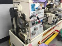
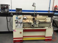
So, I decided to do a little upgrading on the lathe. I have been running it under a VFD, but honestly, it's not been up to snuff because it's been working strictly as a phase converter.

The Leblond Regal servo shift machines are a little trickier to run the spindle motor alone on a VFD because you have to figure a way to be able to switch gears since the servo shift runs off of a separate 1/2 hp three phase motor.

The options are:
Buy a new single phase 1/2 horse motor and wire connections separate from original wiring
Buy new VFD for running servo shift motor
Convert machine to manual shift.

I called Leblond up, who by the way are incredibly helpful, and they told me they sell parts to convert the machines to manual shift for about $500.

I didn't purchase the parts, instead I wanted to see if I could make the parts myself.

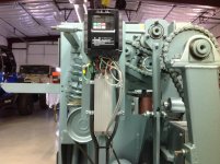
Here's a pic with the top popped on the lathe. The top piece is the servo shift unit. It uses hydraulics to shift gears, with an input dial on the front of the machine for selecting RPM.


http://smg.photobucket.com/user/mte...22-AD29-9679CE1DEAD2_zpssg8dzujw.jpg.html?o=3

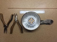
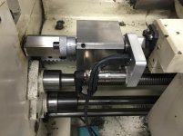
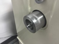
Here's the unit pulled out of the machine. The two arms control the gear changes. http://smg.photobucket.com/user/mte...1E-93DF-C6CAFFBDF77A_zpscv0wxyol.jpg.html?o=2

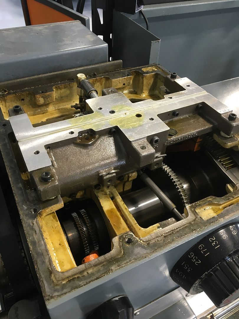
Here's a look at the inside with no servo shift unit. Amazing how clean everything is for this 1978 machine. It looks brand new.


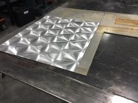
I pulled a cover plate on the front of the machine and found these two rods. They go straight back to the gears. I'm sure glad I didn't pay the $500 bucks for a kit, this is going to be a fairly simple process I believe.


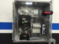
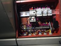
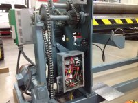
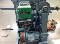
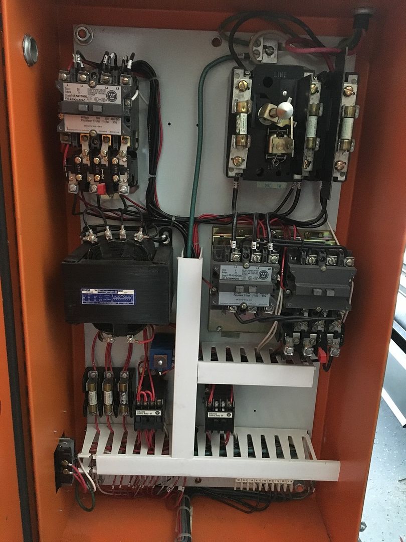
Here's a look at the electrical box for the lathe. It's really complicated at first glance. I'll be able to replace virtually everything in here, run power to a switch then to the VFD. three wires to the motor, two wires from the factory forward/reverse/neutral dial, then a couple wires for the Eaton brake. I haven't quite figured out the brake yet, but I'll get around to that eventually. I'll also run a potentiometer off the VFD so that I can control the speed even further. Fortunately Leblond did an amazing job marking and identifying each wire, along with running the wires in an incredibly clean manner. Makes things much simpler!


It will kinda **** not having the servo shift feature, but honestly it makes a ton of noise so I doubt I'll miss it much. I haven't been able to run the lathe at the high RPM's because the VFD can't act like it should when it runs as a phase converter alone so this will allow me to run it much more efficiently. I'll keep you posted on progress!
 

fnieto

Well-known member
Joined
Aug 27, 2013
Messages
1,401
Location
Tucson,Arizona
Recently completed a new total control system for the 1440 Lathe. A friend designed the system and built the 24V system, while I built and implemented the modification to the Lathe.
All nine machines run from a ultra quiet RPC 7.5 hp system. So the VFD was used for control logic only (Hitachi WJ200-037-LF-200). 24 LED strip lighting added to back splash and the new 24V task light was modified to 12v using a Philips 660 lumen LED.
 

Attachments

  • IMG_1278.jpg
    IMG_1278.jpg
    141.4 KB · Views: 206
  • IMG_1279.jpg
    IMG_1279.jpg
    139.2 KB · Views: 196
  • IMG_1301.jpg
    IMG_1301.jpg
    140.1 KB · Views: 195
  • IMG_1346.jpg
    IMG_1346.jpg
    134.3 KB · Views: 217
  • IMG_1303.jpg
    IMG_1303.jpg
    133 KB · Views: 192
  • IMG_1315.jpg
    IMG_1315.jpg
    147.4 KB · Views: 188
  • IMG_1322.jpg
    IMG_1322.jpg
    146.4 KB · Views: 189

fnieto

Well-known member
Joined
Aug 27, 2013
Messages
1,401
Location
Tucson,Arizona
The entire control board was replaced using 24v. Only the flood coolant remained 240V 3 ph.
The new system has soft start, two position motor braking (1 second and 3-5 seconds) all new upgraded lit switches, (E-stop,flood coolant,jog,micro toggle (braking speed),Hall proximity by-pass button (larger) and potentiometer. The motor as also replaced with a induction/vector type for smooth running. A tachometer was also added as each gear selection has a ten fold speed range.
The hall sensor is incorporated into the carriage stop for fine adjustment with a safety micro switch in case of failure of hall sensor resulting in a E-stop condition and 1 second braking. The repeatability of the proximity sensor is incredible with no more than .00039 (old motor) and .00009 with the new motor. A handy feature for blind boring or internal/external threading. On the motor braking, depending on micro switch position, spindle switch foot brake switch (removed friction shoes) will stop chuck on one second or 3-5 seconds while the E-stop and safety back up micro switch will always default to 1 second. The Jog button is set at 20 Hz for slow rotation. After motor parameters where inputed, a Auto tune was done via lap top.
 

Attachments

  • IMG_1345.jpg
    IMG_1345.jpg
    141.6 KB · Views: 193
  • IMG_1369.jpg
    IMG_1369.jpg
    135.4 KB · Views: 184
  • IMG_1350.jpg
    IMG_1350.jpg
    135 KB · Views: 176
  • IMG_1376.jpg
    IMG_1376.jpg
    132.9 KB · Views: 168
  • IMG_1498.jpg
    IMG_1498.jpg
    146 KB · Views: 166
  • IMG_1516.jpg
    IMG_1516.jpg
    131.8 KB · Views: 162
  • IMG_1382.jpg
    IMG_1382.jpg
    134.5 KB · Views: 182

fnieto

Well-known member
Joined
Aug 27, 2013
Messages
1,401
Location
Tucson,Arizona
For the Tachometer a spider was built and two earth magnets where imbedded for the pick-up probe.
The wall enclosure houses the VFD,fuse blocks,24V power supply,through face disconnect,240v 3ph breakers (flood pump), brake resistor and cooling fan with exhaust. Total build functions perfectly and is a game changer IMO.
 

Attachments

  • IMG_1444.jpg
    IMG_1444.jpg
    132.1 KB · Views: 129
  • IMG_1453.jpg
    IMG_1453.jpg
    131.1 KB · Views: 138
  • IMG_1459.jpg
    IMG_1459.jpg
    138 KB · Views: 129
  • IMG_1509.jpg
    IMG_1509.jpg
    135.7 KB · Views: 138
  • IMG_1457.jpg
    IMG_1457.jpg
    130.1 KB · Views: 135
  • IMG_1381.jpg
    IMG_1381.jpg
    132.7 KB · Views: 152
OP
T

Techie1961

Well-known member
Joined
Feb 18, 2014
Messages
1,520
Location
Pickering Ontario Canada
The entire control board was replaced using 24v. Only the flood coolant remained 240V 3 ph.
The new system has soft start, two position motor braking (1 second and 3-5 seconds) all new upgraded lit switches, (E-stop,flood coolant,jog,micro toggle (braking speed),Hall proximity by-pass button (larger) and potentiometer. The motor as also replaced with a induction/vector type for smooth running. A tachometer was also added as each gear selection has a ten fold speed range.
The hall sensor is incorporated into the carriage stop for fine adjustment with a safety micro switch in case of failure of hall sensor resulting in a E-stop condition and 1 second braking. The repeatability of the proximity sensor is incredible with no more than .00039 (old motor) and .00009 with the new motor. A handy feature for blind boring or internal/external threading. On the motor braking, depending on micro switch position, spindle switch foot brake switch (removed friction shoes) will stop chuck on one second or 3-5 seconds while the E-stop and safety back up micro switch will always default to 1 second. The Jog button is set at 20 Hz for slow rotation. After motor parameters where inputed, a Auto tune was done via lap top.

Beautiful job with some really cool features. The attention to detail is outstanding.
 

manwithtools

ALLIANCE MEMBER
Joined
Aug 24, 2015
Messages
13,639
Location
Lebanon, TN
Very nicely done, applications like this is where a VFD shines.

Just so it does not confuse others, when you say "So the VFD was used for control logic only" I take that to mean that you are using a rotary phase converter to supply three phase power to the VFD and the VFD is providing all speed and direction control of the motor?
 

fnieto

Well-known member
Joined
Aug 27, 2013
Messages
1,401
Location
Tucson,Arizona
Very nicely done, applications like this is where a VFD shines.

Just so it does not confuse others, when you say "So the VFD was used for control logic only" I take that to mean that you are using a rotary phase converter to supply three phase power to the VFD and the VFD is providing all speed and direction control of the motor?

That is correct, The VFD is 3ph in supplied from RPC. I did the same thing to a Plate roller. Ill post up some of those as well.
Thanks
 

fnieto

Well-known member
Joined
Aug 27, 2013
Messages
1,401
Location
Tucson,Arizona
This machine was built and sold to NASA according to the owner of New Dimension. I purchased it back in 05 on Ebay for $2500 from a guy in Riverside CA. He had purchased it at auction from the US Navy. When I got the machine home I was surprised to find a large VFD under the hood (I knew what a VFD was but not much more than that. The machine was setup to run on 440VAC 3 ph. My system was RPC 240 3ph. After spending time on the phone with the manufacture and providing him with the serial # he went on a rant on how NASA required a hour meter and variable speed control along with normal controls found on a Plate roller. He said they only built three of these machine with VFD and stated "they where a real PITA" to build and instead on selling me new contacts and schematics to convert the machine back to basic. I had been able to use the machine but required a large transformer to supply power. I did buy the schematics for $60 and went on a quest to rewire the drive motor and pinch roller motor to 240 but was stuck as the VFD could not be fed 240V. The machine had 10 hours on the meter so the machine was purchased for the right price. I really thought having speed control on plate roller could be beneficial for those oddball troft rolls that require creeping up to a point, so started reading up on VFD and bought my first Hitachi. You can see the size difference in VFD as well as the before and after photos of the control electronics. The factory schematics where a joke but still usable. The original VFD was only used for speed control only (what a waste) and the rest of the controls including motor braking was conventional. New safety upgrades include E-stop, pilot light, run/trip light Fwd,Rvse,speed control,and hour meter. The pinch roller motor is not connected to the VFD. All items are housed within the machine as this machine can be moved around the shop.
 

Attachments

  • IMG_0065_2.jpg
    IMG_0065_2.jpg
    138.8 KB · Views: 242
  • IMG_0541.jpg
    IMG_0541.jpg
    135.1 KB · Views: 211
  • IMG_0063_2.jpg
    IMG_0063_2.jpg
    148.2 KB · Views: 197
  • IMG_0629.jpg
    IMG_0629.jpg
    143.2 KB · Views: 200
  • IMG_0627.jpg
    IMG_0627.jpg
    140.1 KB · Views: 204
  • IMG_0577.jpg
    IMG_0577.jpg
    133.9 KB · Views: 202
  • 20150509_171128.jpg
    20150509_171128.jpg
    146.4 KB · Views: 188
To avoid these ads, REGISTER NOW!
Top Bottom