Here is the manual,
http://dealerselectric.com/images/Products/teco/fm50_instruction_&_user_manual.pdf
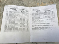
Pages, 11 & 13 have the power and breaker specs.
The breaker specs show a 20 A breaker with 14 gauge wire.
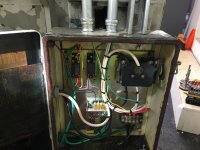
I have single phase incoming line power.
http://dealerselectric.com/images/Products/teco/fm50_instruction_&_user_manual.pdf
Pages, 11 & 13 have the power and breaker specs.
The breaker specs show a 20 A breaker with 14 gauge wire.
I have single phase incoming line power.


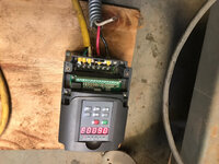


 it looks like it is 0-400 hz operating range. Nines, did you have any luck with this?