
You are using an out of date browser. It may not display this or other websites correctly.
You should upgrade or use an alternative browser.
You should upgrade or use an alternative browser.
Show us your welding projects
- Thread starter neonnblack
- Start date
steel 35
Well-known member
Some nice looking projects on here guys!!
Here are some more pics of the sandcar I've been rebuilding.
Wish I would have got a few pictures at dune fest last weekend! Keep posting

ZTFab
Well-known member
ZTFab could you tell me what settings your at? Oh and those are some kick *** beads!
Thanks.
Settings varied as the part is made up of varying thicknesses from .074"-.134".
Rough machine settings for my Syncrowave 250 were 140 base amps, foot pedal for control, 3/32" thoriated tungsten and varying fillers between .045" and 1/16".
Hope that helps!


GarageEnvy
Well-known member
Holy Shite! If that welding was any prettier I'd want to stick my d*ck in it! QUOTE]
I think we now know when your welds are good enough and when to stop trying to improve.
NASTYZEN
Well-known member
You should never stop trying to improve! That's what great about having awesome welders like ZTFab post there work. Makes us work harder to try to come close to his standards. Impossible for me, but I can keep on trying.....
Today's project. A rear upright from a 86 Reynard Formula Ford.
Bearing disintegrated and messed things up.

Wannabe welder touched up the caliper mount.....

Incredible the stuff on some of these cars. LoL!

The top and bottom sheet metal was ok, so only the center bearing hub and caliper brkt had to be reproduced. So as to save time n money for the owner.
Cutting some 3 1/2'' mechanical tubing.

Le new hub, all machined and bearing fit test. I made it .002'' bigger to allow for shrinkage from welding.

Cutting the bad stuff off.

I love leaving Kilroy inside things for the next guy.

I have all kinds of jigs and fixtures from over the years. I happened to have one for this model. Yes!
A bit of fitting

Welded up before adding the caliper mount.

Card board template.

Ready for welding.

All done.

Ready to go back to the front.

Today's project. A rear upright from a 86 Reynard Formula Ford.
Bearing disintegrated and messed things up.
Wannabe welder touched up the caliper mount.....
Incredible the stuff on some of these cars. LoL!
The top and bottom sheet metal was ok, so only the center bearing hub and caliper brkt had to be reproduced. So as to save time n money for the owner.
Cutting some 3 1/2'' mechanical tubing.
Le new hub, all machined and bearing fit test. I made it .002'' bigger to allow for shrinkage from welding.
Cutting the bad stuff off.
I love leaving Kilroy inside things for the next guy.
I have all kinds of jigs and fixtures from over the years. I happened to have one for this model. Yes!
A bit of fitting
Welded up before adding the caliper mount.
Card board template.
Ready for welding.
All done.
Ready to go back to the front.
Last edited:
Honch
Well-known member
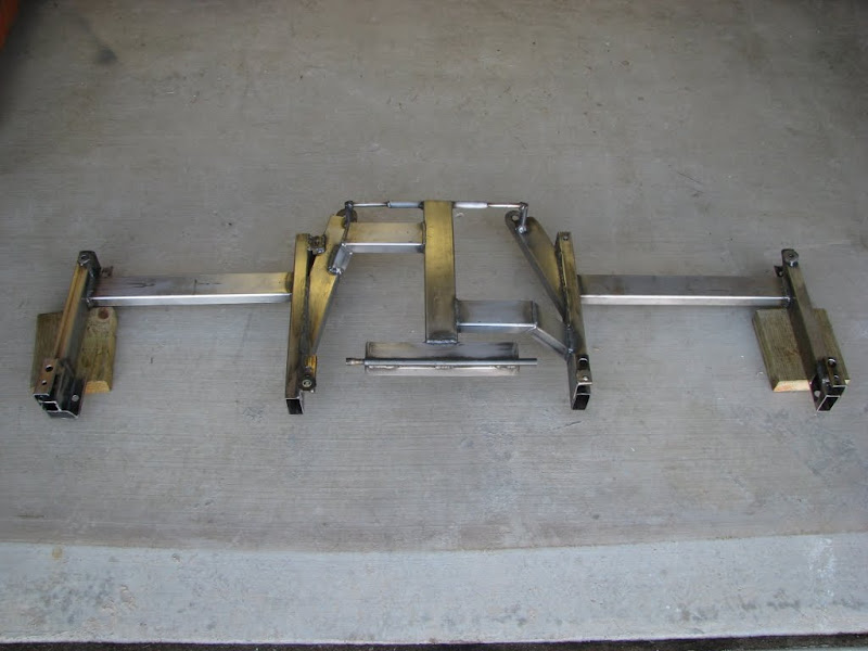
This is a project I did a while back. I found some leather second row seats removed new from a 2010 Odyssey. They had quick release fittings which I took off and replaced with a fabricated seat rail. The cloth bench in my pickup had four mount points, one at each corner, drilling new holes for me is a last resort so I used the existing mount holes and also tied into the seat belt mounts.
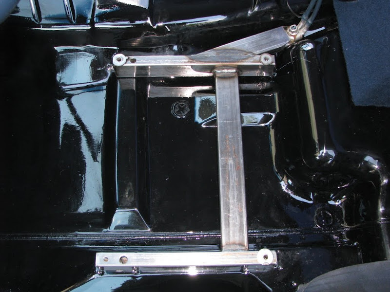

The Odyssey seats have integral seat belts on the receptacle side, to compensate for this, I made the seat tracks much beefier than would be necessary to just mount a seat. Because an Odyssey does not have a transmission tunnel the center seat was 7" too tall. I sectioned this out of the seat base and retained the quick release feature of the seat. This made the storage compartment in the seat much smaller but it still folds down to provide an arm rest and cup holders.


The Odyssey seats have integral seat belts on the receptacle side, to compensate for this, I made the seat tracks much beefier than would be necessary to just mount a seat. Because an Odyssey does not have a transmission tunnel the center seat was 7" too tall. I sectioned this out of the seat base and retained the quick release feature of the seat. This made the storage compartment in the seat much smaller but it still folds down to provide an arm rest and cup holders.
zmotorsports
ALLIANCE MEMBER
You should never stop trying to improve! That's what great about having awesome welders like ZTFab post there work. Makes us work harder to try to come close to his standards. Impossible for me, but I can keep on trying.....
Today's project. A rear upright from a 86 Reynard Formula Ford.
Bearing disintegrated and messed things up.
Wannabe welder touched up the caliper mount.....
Incredible the stuff on some of these cars. LoL!
The top and bottom sheet metal was ok, so only the center bearing hub and caliper brkt had to be reproduced. So as to save time n money for the owner.
Cutting some 3 1/2'' mechanical tubing.
Le new hub, all machined and bearing fit test. I made it .002'' bigger to allow for shrinkage from welding.
Cutting the bad stuff off.
I love leaving Kilroy inside things for the next guy.
I have all kinds of jigs and fixtures from over the years. I happened to have one for this model. Yes!
A bit of fitting
Welded up before adding the caliper mount.
Card board template.
Ready for welding.
All done.
Ready to go back to the front.
Very nice as usual. I always enjoy looking at the projects that you do and the quality in which you perform them. Good work.
Mike.
NASTYZEN
Well-known member
Very nice as usual. I always enjoy looking at the projects that you do and the quality in which you perform them. Good work.
Mike.
Thank you for the kind words.
The same could be said about your work, Mike. Top notch!
Claude
NASTYZEN
Well-known member
This is a project I did a while back. I found some leather second row seats removed new from a 2010 Odyssey. They had quick release fittings which I took off and replaced with a fabricated seat rail. The cloth bench in my pickup had four mount points, one at each corner, drilling new holes for me is a last resort so I used the existing mount holes and also tied into the seat belt mounts.
necessary to just mount a seat. Because an Odyssey does not have a transmission tunnel the center seat was 7" too tall. I sectioned this out of the seat base and retained the quick release feature of the seat. This made the storage compartment in the seat much smaller but it still folds down to provide an arm rest and cup holders.
Nice. They look comfy.
ZTFab
Well-known member
Thanks ZT, that info is great. I wanted to know if my settings in my head were in the ball park.
Looks really good Bar Ditch!
Very nice as usual. I always enjoy looking at the projects that you do and the quality in which you perform them. Good work.
Mike.
x2 I like seeing your projects NZ. The history and pedigree of some of your projects alone make them fun to look along with the quality of your work and attention to detail.
Nice. They look comfy.
x2. They look great.
zmotorsports
ALLIANCE MEMBER
Some nice looking projects on here guys!!
Here are some more pics of the sandcar I've been rebuilding.
Got the motor mounts designed and built.


Paul, your work simply amazes me. I am often very humbled when I see your welds. It really inspires me to constantly improve.
Keep up the awesome work.
One quick question, do you pump the pedal when TIG welding? I was watching a video the other night where a weldor who was fabricating top fuel chassis was pumping the hell out of the pedal while welding. The welds looked great when done and I have heard of people pulsing the current like that but I generally stay pretty consistant and use the rythym of the move and dip to create the puddles. Just wondering what your technique is.
Thanks.
Mike.
ZTFab
Well-known member
Paul, your work simply amazes me. I am often very humbled when I see your welds. It really inspires me to constantly improve.
Keep up the awesome work.
One quick question, do you pump the pedal when TIG welding? I was watching a video the other night where a weldor who was fabricating top fuel chassis was pumping the hell out of the pedal while welding. The welds looked great when done and I have heard of people pulsing the current like that but I generally stay pretty consistant and use the rythym of the move and dip to create the puddles. Just wondering what your technique is.
Thanks.
Mike.
Thanks Mike.
90% of the time I run constant but there are times when pulsing the peddle can help.
The above welds were all done with a constant peddle and a standard dip/move technique.
On thin outside corner joints or when you run across a small bit of contamination, pulsing the pedal can help. If/when I do pulse at all it is a very small amount to maintain proper heat control or bead width.
Hope that helps.
- Paul
NASTYZEN
Well-known member
x2 I like seeing your projects NZ. The history and pedigree of some of your projects alone make them fun to look along with the quality of your work and attention to detail.
.
Thank you Paul, specially sweet compliment ,coming from you.

Here's a not so fancy repair I did on an Alu. sail boat auxiliary outboard motor throttle that broke off when the owner dropped it, pulling it out of his car trunk.

Taken apart and prepped before welding.

Happy sailing.

zmotorsports
ALLIANCE MEMBER
Thanks Mike.
90% of the time I run constant but there are times when pulsing the peddle can help.
The above welds were all done with a constant peddle and a standard dip/move technique.
On thin outside corner joints or when you run across a small bit of contamination, pulsing the pedal can help. If/when I do pulse at all it is a very small amount to maintain proper heat control or bead width.
Hope that helps.
- Paul
Paul, that helps alot. Thank you. Like you, I have had to pulse the pedal once in a while as well depending on if there is some contamination or maybe a thin section that I want to taper off a little to cool for a fraction of a second before hitting it with the current again, mainly to keep from blowing through. However, the guy I saw on the video was pumping/pulsing the pedal consistantly to add current then let cool slightly before moving the torch and then blasting it with current again. I had just never seen that before.
Thanks again. I guess I am on the right track. I have a long way to go before I get to your level but I am working on it. I appreciate the advice/insight.
Mike.
So I've been practicing like 1-3hrs a day and reading about welding at night  I'm about a month in and things are moving along pretty good. I just got 40ft of 1.5x1/8" 6061 dropped off just for practice joints and working on consistency. I wasn't going to weld today but couldn't help myself, welded up this overflow tank as fast as i could just to see what would happen, start to finish took about 2.5hrs running back and forth to the car between tacks then final weld. i'm probably going to give it a brushed finish later since i didn't take the time to pretty up the base metal before welding. I also did the catch can in the pick about a week earlier.
I had some 2% lanthanated 1/6th tungsten in the torch and also decided to try it vs the normal 3/32, and it worked pretty good. when i first started welding corner joints on 1/8 i started with 90amps and moving slow. I've slowly worked my speed up to 118amps and the beads lay down way faster and they are really shiny.
1/8" 6063, 118 amps, 1/16 2% lanthanated, 3/32 4043 filler, 125hz, 70% balance, no pulse
Started on the bottom first to get a hang of the settings, also cause fitment was horrible on the bottom which is why the vertical (in the pic) welds are rougher then the rest. welded all that in like 3min, then let it cool and did the rest. bungs are welded in from the rear.


I'm about a month in and things are moving along pretty good. I just got 40ft of 1.5x1/8" 6061 dropped off just for practice joints and working on consistency. I wasn't going to weld today but couldn't help myself, welded up this overflow tank as fast as i could just to see what would happen, start to finish took about 2.5hrs running back and forth to the car between tacks then final weld. i'm probably going to give it a brushed finish later since i didn't take the time to pretty up the base metal before welding. I also did the catch can in the pick about a week earlier. I had some 2% lanthanated 1/6th tungsten in the torch and also decided to try it vs the normal 3/32, and it worked pretty good. when i first started welding corner joints on 1/8 i started with 90amps and moving slow. I've slowly worked my speed up to 118amps and the beads lay down way faster and they are really shiny.
1/8" 6063, 118 amps, 1/16 2% lanthanated, 3/32 4043 filler, 125hz, 70% balance, no pulse
Started on the bottom first to get a hang of the settings, also cause fitment was horrible on the bottom which is why the vertical (in the pic) welds are rougher then the rest.
welded all that in like 3min, then let it cool and did the rest. bungs are welded in from the rear.
Last edited:
So checkin out everbody's posts made me realize that I should probably contribute some more so heres a vise stand and a Craftsmen vise I restored yesterday. The stand is made from a ford truck rim, a section of railroad track and a piece of 3/8 plate. I used 7013 for the track to the rim and Tig welded the plate. Enjoy


Maexle
Well-known member
So I've been practicing like 1-3hrs a day and reading about welding at night
I had some 2% lanthanated 1/6th tungsten in the torch and also decided to try it vs the normal 3/32, and it worked pretty good. when i first started welding corner joints on 1/8 i started with 90amps and moving slow. I've slowly worked my speed up to 118amps and the beads lay down way faster and they are really shiny.
1/8" 6063, 118 amps, 1/16 2% lanthanated, 3/32 4043 filler, 125hz, 70% balance, no pulse
Started on the bottom first to get a hang of the settings, also cause fitment was horrible on the bottom which is why the vertical (in the pic) welds are rougher then the rest.
very nice, respect !!
I dont want to sound like an ***, but can you please cut most of the photos out when you quote someone.
Its brutal on my phone (as Im sure it is on others) when I check on this thread and the same photos are posted several times on the same page.
Thanks
Its brutal on my phone (as Im sure it is on others) when I check on this thread and the same photos are posted several times on the same page.
Thanks
ZTFab
Well-known member
ZTfab, is that SolidWorks?
Yep, Solidworks 2012.
NASTYZEN
Well-known member
A bit of an unusual welding job.
Mustang hit the wall side ways and broke the wing mounts almost completely off.
I've never seen a wing put together like this. It is made of such heavy gauge material, that the mounts are welded on!??
No damage other than that. It's so darn heavy that when the sudden stop occurred, the inertia broke the welds.
Cleaned up and ready to go.


Best I could do while holding my breath and thinking of ZTfab.

Done.

The Stang it belongs to, after body work. Minus the wing.


Thank's Yvan!
Mustang hit the wall side ways and broke the wing mounts almost completely off.
I've never seen a wing put together like this. It is made of such heavy gauge material, that the mounts are welded on!??
No damage other than that. It's so darn heavy that when the sudden stop occurred, the inertia broke the welds.
Cleaned up and ready to go.
Best I could do while holding my breath and thinking of ZTfab.
Done.
The Stang it belongs to, after body work. Minus the wing.
Thank's Yvan!
zmotorsports
ALLIANCE MEMBER
Looks good as usual.
Nice looking stacker trailer in the background. Any pictures of the Prevost that tows it? Is it yours or a clients?
Mike.
Nice looking stacker trailer in the background. Any pictures of the Prevost that tows it? Is it yours or a clients?
Mike.
y20dth
Well-known member
AFTER bodywork? they still need to fix the real axle then?
Or is that the reason why musclecars wanna go sideways?
Or is that the reason why musclecars wanna go sideways?
NASTYZEN
Well-known member
Looks good as usual.
Nice looking stacker trailer in the background. Any pictures of the Prevost that tows it? Is it yours or a clients?
Mike.
Thank's Mike,
I was on site at ICAR at my friends shop. Someone else's rig and car.
My 16year old in the second shot and my new to me F250.
I'm sure I could do a fine job of putting the Stang in the wall though.
AFTER bodywork? they still need to fix the real
axle then?
Or is that the reason why musclecars wanna go sideways?
Yeah, I guess they fixed all that too. $$$
cyamaha2007
Well-known member
Nastyzen whats with the garage door support angle being used for in the back of the stang. Am i missing something? Your repair looks top notch.
Looks good as usual.
Nice looking stacker trailer in the background. Any pictures of the Prevost that tows it? Is it yours or a clients?
Mike.
That Prevost IS a trailer! look close and you can see the door.
A bit of an unusual welding job.
Mustang hit the wall side ways and broke the wing mounts almost completely off.
I've never seen a wing put together like this. It is made of such heavy gauge material, that the mounts are welded on!??
No damage other than that. It's so darn heavy that when the sudden stop occurred, the inertia broke the welds.
Cleaned up and ready to go.
I like the use of the ground clamp as a holding fixture. Very clever.
Last edited:


warren57
Well-known member
Got tired of rolling around on the ground to weld/fabricate so yesterday I dug out some junk steel and built a fab table...
http://www.garagejournal.com/forum/attachment.php?attachmentid=204827&stc=1&d=1346038802
http://www.garagejournal.com/forum/attachment.php?attachmentid=204827&stc=1&d=1346038802
Attachments

NASTYZEN
Well-known member
Nastyzen whats with the garage door support angle being used for in the back of the stang. Am i missing something? Your repair looks top notch.
Thank's.
Didn't notice the perf. angle t'ill you pointed it out.
The stuff you find on race cars........... guess that's all they had on hand at the time.
Not my handiwork nor my friends Yvan's.
NASTYZEN
Well-known member
I like the use of the ground clamp as a holding fixture. Very clever.
Thank's, also keeps you from arcing big holes in things.
zmotorsports
ALLIANCE MEMBER
That Prevost IS a trailer! look close and you can see the door.
Prevost is a coach/bus chassis manufacturer out of Canada. They used to manufacture trailers to match their coaches but don't anymore. By looking at the trailer I am guessing that it either an ATC, T&E, Optima or possibly a Pace or Haulmark with the Prevost insignia painted on the rear of the trailer, I would assume to match the Prevost coach that tows it.
Mike.
W_A_Watson_II
Well-known member
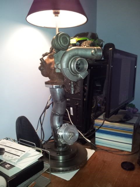
Decided to put wheels under the "Spare Engine". Makes it easier to move than with the engine hoist.

BD1
Well-known member
Decided to put wheels under the "Spare Engine". Makes it easier to move than with the engine hoist.
Nice, please post some pics of POWER WAGON.

SiGmA_X
Well-known member
http://powerwagon.wawii.com/Nice, please post some pics of POWER WAGON.
http://powerwagon.wawii.com/46.html
From the dudes signature...
BD1
Well-known member
THANKS !!!
A**holes Garage
Banned
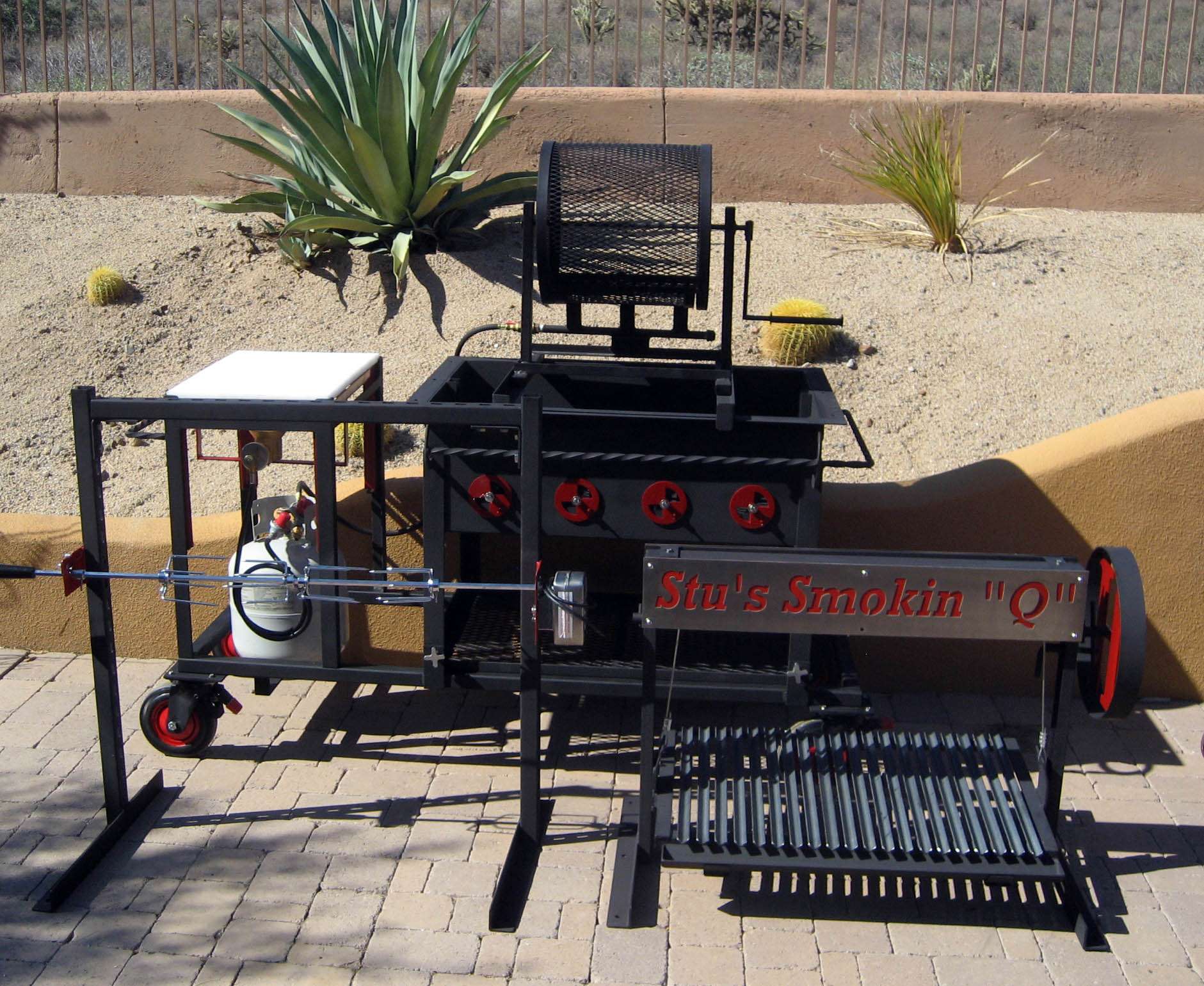
Just finished my Santa Maria Grill with interchangeable rotisserie and chili roaster. 160K BTU removeable gas burner;

Build slide show;
http://img210.imageshack.us/slideshow/webplayer.php?id=19610318.jpg
Build slide show;
http://img210.imageshack.us/slideshow/webplayer.php?id=19610318.jpg