A lot came together on this project very well but today I made one really big mistake and discovered another that I made weeks ago.
This is supposed to be a rack to store 8 - 10 Rubbermaid plastic bins. One thing I'm really happy about is that I was able to control welding distortion pretty well. Considering I don't have a proper welding table, it came out very square. The Miller folding table in the pic is not perfectly flat. It's actually slightly convex shaped. I put the shelf frames on four small wood blocks and tried to distribute them evenly. That kept them all on the same plane.
This is one of the shelves ( 14 ga. 1" sq.). The idea is that this will hold two bins side by side stacked 2 high:
View media item 52080
Here's a closeup of one of the welds:
View media item 52081
Here it is primed. I did not weld the joints at the top and bottom. I figured the sides were good enough and I didn't want to have to grind them down on the top where I might put a sheet of something if I feel the need.
View media item 52082
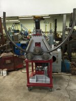
The shelves are one thing but the assembly is way too big for the folding table. I put two 2" sq tubes on saw horses and leveled them with one another. That's the best I could do. Notice that the middle shelf is up against angle brackets and the assembly is oriented with the bottom on the right (more on that in a minute). The angle brackets were really meant to just locate the middle shelf a fixed distance from the bottom. Since I used them, I only tacked the middle shelf in place. The bottom and top shelves are joined on three sides to the verticals.
View media item 52083
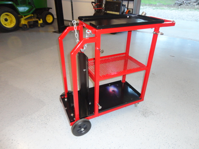
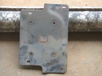
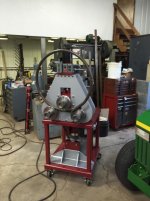
Here it is standing up. Fabulous. Almost. In order to make it easier to weld, I rotated the assembly at some point so that the bottom was facing left. But I forgot that and welded the plates for the casters on the right (what should have been the top).
 View media item 52084
So, now my shelf supports are above the middle shelf instead of below it. Friggen' brilliant!
 View media item 52086
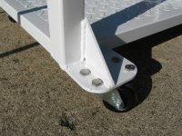
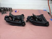
Here are the 3" casters. $16 at tractor supply. The are a bit clunky but they have really good parking brakes.
View media item 52085
The final insult came when I put one of the Rubbermaid bins on a shelf and found that I really didn't need to make the thing as deep as I did. I could have made it about 6" shallower.